Energy and Power Engineering, 2013, 5, 1105-1108
doi:10.4236/epe.2013.54B211 Published Online July 2013 (http://www.scirp.org/journal/epe)
Calculation of Eddy Current Loss and Short-circuit
Force in SSZ11-50000/110 Power Transformer
Yan Li1, Bo Zhang1, Longnv Li1, Tongxun Yang2, Ning Wang2
1Power Transmission Technology Research Institution, Shenyang University of Technology, Shenyang
2TBEA Shenyang Transformer Group Co., Ltd. Shenyang
Email: solomon.zb@163.com
Received April, 2013
ABSTRACT
The method is used in this paper to calculate the leakage magnetic field of SSZ11-50000/110 Power trans-
former, and by which the structures’ influences to the main leakage flux are analyzed. Through the combination of the
product and TEAM Problem 21B, the surface impedance method shows its great advantage in the calculation of eddy
current loss.
T
Keywords: Power Transformer; Finite Element; Short-circuit Force; Eddy Current Loss; Surface Impedance Method
1. Introduction
With the rising of voltage level and transformer capacity ,
the leakage flux of transformer increased, therefore, the
problem of structural part stray loss and short-circuit
strength has became one of urgent key technical issues
both in transformer companies and operation department.
To solve this type of problem, intra-industry corre-
sponding standards are already existed, and it changes
with the products upgrade.
The traditional analytical method cannot analysis the
local overheating, short circuit mechanical force withstand
capability and three-dimensional spatial distribution of
leakage flux which the new standards request. Based on
three-dimensional finite element numerical method, the
paper introduced transformer design criterion to discuss
the leakage flux distribution, short circuit strength, and
eddy current loss of transformer, and the fitted engineer-
ing design loss calculation numerical method is also pr-
oposed [1,2].
2. Mathematical Model
The method which uses scalar magnetic potential
and electric vector potential can reduce unknown number
and save computer memory when high precision is re-
quired.
T
The governing equations in eddy zone is

1
σε TμT0
t()
t



 






(1)
penalty function is introduced,
1
σε T
t

 


, then

11
σε Tσε T
μT0
tt
()
t



 
 

 

 



(2)
0B
, then
μ()T0

(3)
The governing equations in non-eddy zone is
μH
s
()0
  (4)
where, Hs is the magnetic field produced by source cur-
rent in infinite space, T is electric vector potential,
is
scalar magnetic potential, is conductivity, is di-
electric constant,
σε
μ
is permeability.
The calculation process is treated as follows:
1) According to structural symmetry, the half trans-
former model is taken into calculation (as shown in Fig-
ure 1);
2) Circulation and eddy current in winding, and eddy
current in core is neglected;
Using wire winding, and the current density is uniform
in the winding.
N
I
S
(5)
where J is winding current density, N is winding turns, S
is sectional area, I is winding current;
*This work was supported by NSFC, under Project 51177103 and
Program for LNIRT in University (LT2011002).
Copyright © 2013 SciRes. EPE
Y. LI ET AL.
1106
3) Material of iron core is according to rolling direc-
tion and orthogonal opposite treated. The material of tank,
draw plate and clamping part are treated according to
each direction same treated. The basic magnetization
characteristic curve is used here and hysteresis charac-
teristic is neglected.
4) The Newton-Raphson algorithm is used to solve the
magnetization characteristic of core silicon steel sheet
and tank steel plate for their characteristic are nonlinear
relation.
5) The eddy zone produce skin effect, and mesh gen-
eration should take current density radial distance.
1
f

(6)
where
is penetration depth,
f
is frequency,
is
conductivity,
is permeability. According to field
value some gradient descent discipline to stratify, pene-
tration depth chooses 0.22, 0.51, 0.92, 1.6 and 5 times to
mesh generation.
3. Field Analysis
To analysis short-circuit electromagnetic force, the flux
leakage magnetic distribution should be studied first.
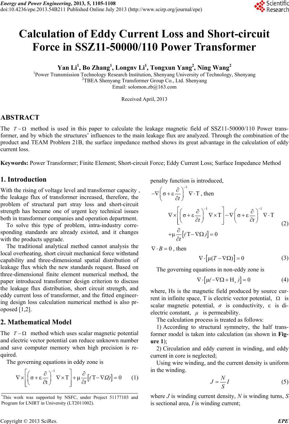
As shown in Figure 2 that winding average flux den-
sity along circumferential distribution, winding end
magnetic density is affected by upper and lower iron yok,
the inner magnetic density is higher than the outers’. The
radiation component Br value is impacted greatly from
24.35mT to 27.8mT. The axis component Bz value varies
from 58.4mT to 61.6mT, and both of their two sides are
more than that at the middle part. The middle of the
winding does not change greatly for its far distant form
clamping part and iron yoke.
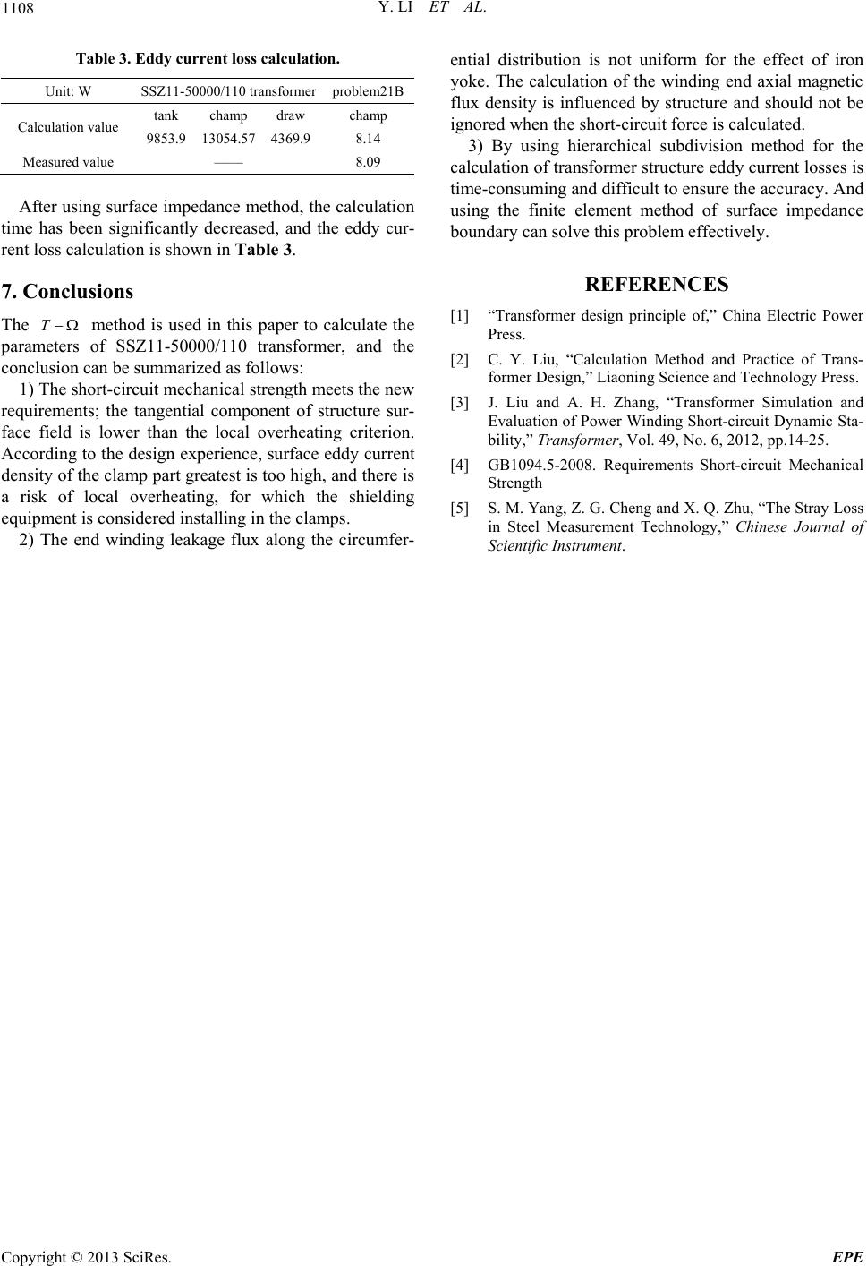
For the anglicizing of the structure eddy current loss,
the surface field and eddy current distribution are the
emphases.
As shown in Figure 3 that the magnetic curve of outer
tank side winding end part is bend, and the vortex center
is formed for the leakage flux concentrated into the tank
surface.
tank
Draw
Plate Pp
champing
Figure 1. Transformer calculation model.
Figure 2. Winding average fl ux density along circumferential
distribution.
Vo rtex
center ble
stress
requireme
nts g7
Figure 3. The surface of the oil tank eddy current distribu-
tion.
According to the CIGRE recommended document , the
transformer metal structure of local overheating criteria,
through calculation, the tank surface magnetic field
strength of the tangential component maximum value
was 48.22A • cm-1, does not exceed the standard value of
60 A • cm-1, therefore, the additional fuel tank shield is
not necessary.
4. Short Circuit Strength
The national standard GB1094.5-2008, in the new ver-
sion, the allowable stress requirements of .conventional,
non - viscous, sticky wire and CTCs (continuous trans-
posed conductor) are different from the original design.
Now, take average ring stress t1
, warping free limit
stress cr
, the inner winding radial bending stress sav
,
axial compressive stress act
, conductor axial bending
stress AL
, and wire inclination critical stress _cr tilt
for example [3,4]
According to the national standard GB1094.2-2008,
the first peak of asymmetric short-circuit current is
2
k
ik
IU

(7)
where, i is rated current effective value, k
U is short
circuit impedance, 2k is peak factor, in this paper
Copyright © 2013 SciRes. EPE
Y. LI ET AL. 1107
the transformer is valued 2.55.
According to the Lorenz formula, the winding elec-
tromagnetic force can be calculated., The SSZ11-50000/
110 transformer short-circuit force calculated values and
national standard GB1094.5-2008 requirements short-
circuit mechanical strength are shown in Table 1.
Through calculation, the low-voltage windings of
power transformer SSZ11-50000/110 meet the national
standard GB1094.5-2008 to withstand short-circuit me-
chanical strength requirements.
5. Eddy Current Loss
Eddy current density can be calculated by the following
formula
e(σV
t
 
A
J)
(8)
Eddy current loss
2
e
eσ
v
pJdv
(9)
where, Je is eddy current densitype is Eddy current loss,
Ais magnetic vector potentialV is electric scalar po-
tential.
As shown in Figure 4, the maximum point appears in
the main empty path up(down) direction, base on design
experience ,the structural overheating criterion is shown
in Table 2
Table 1. SSZ11-50000/110 anti short-circuit stability.
t1
(MPa) cr
(MPa) sav
(MPa)
Calculation value 38.24 11.70 66.01
National standard 49 98 126
act
(MPa) AL
(MPa) tiltcr_
(MPa)
Calculation value 50 75.51 28.32
National standard 80 126 98
i
n
side
outside
Figure 4. The eddy current loss density distribution of Clamp
part.
Table 2. Large transformer partial overheat judgment.
Structure part maximum loss density / kW·m-3
tank 1800
champ 1800
Through calculation, the highest tank eddy current loss
density is 1066.3 kW • m-3. And the clamp part maxi-
mum loss density is 2100.5 kW • M-3, which exceed the
empirical criterion. Through taking effective measures,
the possible overheating is prevented.
6. Surface Impedance Method
When eddy current loss in transformer is under calcula-
tion, if more structures exists namely the vortex area ac-
counts for a larger proportion of the solution domain, it
will lead to a large amount of computer memory occu-
pied.
After taking into the consideration of the skin effect,
the refinement of mesh in the penetration depth is also
needed. Even using hierarchical subdivision method, a
smaller grid is still needed to meet the needs of accuracy.
Taking TEAM Problem 21B as an example [5], the
relations of steel plate maximum length and the calcu-
lated value eddy current loss is shown as Figure 5.
When the maximum length of the element is 5 mm, it
will cost one hour to reach the experimental values to
meet the precision need, and the method can not be ap-
plied in the calculation model because the structure size
growth several times which makes the calculation up to
tens of hours.
When the skin depth is small, the surface of eddy re-
gion is regarded as the impedance boundary conditions
for solving domain, and the finite element method are
still used in other domains that can obviously reduce the
problem scale.
The surface impedance eddy zone definition

1
1
t
s
t
E
f
j
Zj
H


 (10)
where
s
Z
is surface impedance, is tangential
component of electric field intensity,
t
E
t
H
is tangential
component of magnetic field intensity,
is penetration
depth.
Solid line: the calculated values; dotted line: measured value
Figure 5. 21B relations of maximum element length and
calculation value.
Copyright © 2013 SciRes. EPE
Y. LI ET AL.
Copyright © 2013 SciRes. EPE
1108
Table 3. Eddy current loss calculation.
Unit: W SSZ11-50000/110 transformer problem21B
tank champ draw champ
Calculation value 9853.9 13054.57 4369.9 8.14
Measured value —— 8.09
After using surface impedance method, the calculation
time has been significantly decreased, and the eddy cur-
rent loss calculation is shown in Table 3.
7. Conclusions
The method is used in this paper to calculate the
parameters of SSZ11-50000/110 transformer, and the
conclusion can be summarized as follows:
T
1) The short-circuit mechanical strength meets the new
requirements; the tangential component of structure sur-
face field is lower than the local overheating criterion.
According to the design experience, surface eddy current
density of the clamp part greatest is too high, and there is
a risk of local overheating, for which the shielding
equipment is considered installing in the clamps.
2) The end winding leakage flux along the circumfer-
ential distribution is not uniform for the effect of iron
yoke. The calculation of the winding end axial magnetic
flux density is influenced by structure and should not be
ignored when the short-circuit force is calculated.
3) By using hierarchical subdivision method for the
calculation of transformer structure eddy current losses is
time-consuming and difficult to ensure the accuracy. And
using the finite element method of surface impedance
boundary can solve this problem effectively.
REFERENCES
[1] “Transformer design principle of,” China Electric Power
Press.
[2] C. Y. Liu, “Calculation Method and Practice of Trans-
former Design,” Liaoning Science and Technology Press.
[3] J. Liu and A. H. Zhang, “Transformer Simulation and
Evaluation of Power Winding Short-circuit Dynamic Sta-
bility,” Transformer, Vol. 49, No. 6, 2012, pp.14-25.
[4] GB1094.5-2008. Requirements Short-circuit Mechanical
Strength
[5] S. M. Yang, Z. G. Cheng and X. Q. Zhu, “The Stray Loss
in Steel Measurement Technology,” Chinese Journal of
Scientific Instrument.