Y. LI ET AL.
Copyright © 2013 SciRes. EPE
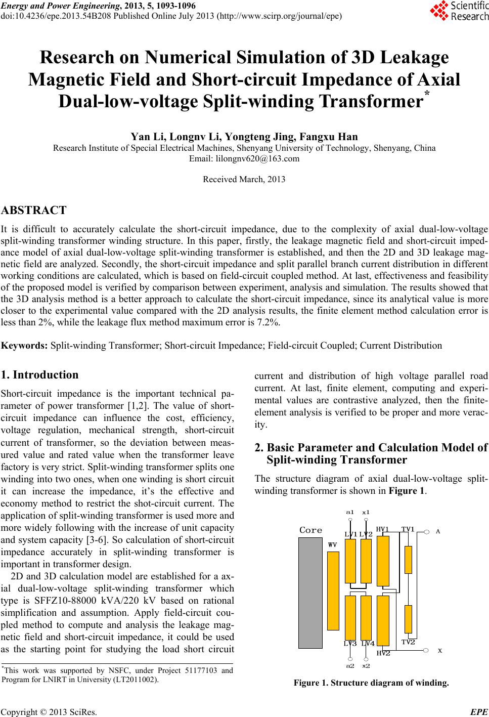
1096
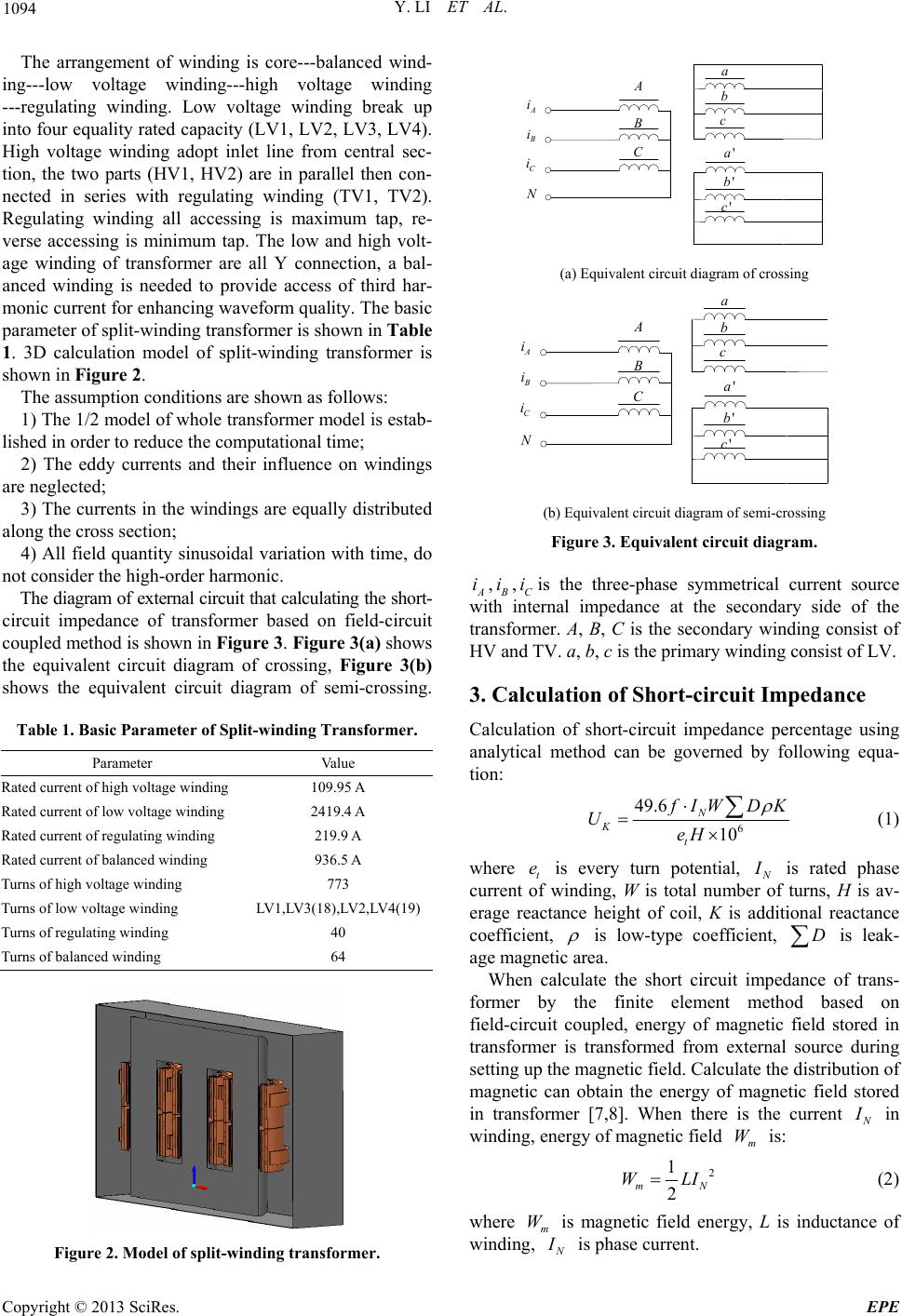
Table 3. Current calculation of HV parallel branch (-show
phase contrast).
Calculation conditions High voltage
up/A High voltage
down/A
Zd 109.95 110.14
ZB(high/low-up) 111.02 -1.08
Rated tap
ZB(high/low-down) -1.11 111.02
Zd 104.62 104.88
ZB(high/low-up) 108.62 -3.66 Max tap
ZB(high/low-down) -3.67 108.62
Zd 129.13 129.67
ZB(high/low-up) 120.92 8.46 Min tap
ZB(high/low-down) 8.45 120.93
winding from the figure, the magnetic flux density in the
core window is larger than that out of the core window.
The comparative analysis of the analytical method, 2D
finite element method, 3D finite element method and
measured values shows that the 3D finite element calcu-
lation value is more close to the measured value. Due to
short-circuit impedance is decided by the value and re-
gularity of distribution of leakage magnetic field, ana-
lytical method can not calculate the leakage magnetic
accurately. 2D finite element method can not figure up
the uneven of the distribution of magnetic field along the
circle direction of winding. So the 3D finite element me-
thod is the best choice when calculating short-circuit
impedance.
5. Analysis of Current Distribution
In this paper, the high voltage winding is connected in
parallel, then series connected with regulating winding,
current excitation is applied at high voltage side when
calculating short-circuit impedance from Figure 1. The
problem of current distribution is analyzed in different
conditions, the calculation results of 3D finite element
method are shown in Table 3.
Table 3 shows that the high voltage parallel branch
current in crossing is not much different and equal divi-
sion when in the three conditions; current in
semi-crossing is different and distribution uneven. The
reason for this phenomenon is that: under the
semi-crossing, the two low voltage winding impedances
are different in the up and down two parallel branches,
and the magnetic field is mutual affected. At last, a circle
flowing the two low-voltage winding is emerged to
counteract the imbalance of impedance.
6. Conclusions
In this paper, an axial dual-low-voltage split-winding
transformer is selected as the research object, calculation
model of the equivalent circuit and the leakage magnetic
field is established. Analytical method, 2D and 3D finite
element method are used to calculate the short-circuit
impedance of transformer in different conditions, then
get the following conclusions:
1) The error of 3D finite element and measured values
is in 2%. The maximum error of analytical method
achieves 7.2%. The 3D finite element method is more
accurate than the 2D one and analytical method.
2) The current distribution can be accurately obtained
by 3D field-circuit coupled finite element analysis me-
thod though the analysis of current distribution of high
voltage parallel branch, then the precise short-circuit
impedance is gained. All of these can be the reference
frame in the short-circuit design of split-winding trans-
former.
REFERENCES
[1] S. S. Wang, Y. M. Li and Y. N. Guo, “Calculation of
Short-circuit Impedance for Power Transformer with
Coupling FEM Method of Magnetic Field and Circuit,”
High Voltage Engineering, Vol. 32, No. 11, 2006, pp.
11-14.
[2] B. R. Xie, Q. F. Chen and X. S. Li, et al., “Calculation of
the Short-circuit Impedance of the Transformer with Split
Types of Windings Using Three-dimensional FEM,”
High Voltage Engineering, Vol. 33, No. 6, 2007, pp.
97-101.
[3] K. F. Qu, W. Zhao and B. Jiang Bo, et al., “3D FEM
Computation of Magnetic Field of Heavy Current Trans-
former with Shielding Coils,” High Voltage Apparatus,
Vol. 45, No. 1, 2009, pp. 25-32.
[4] P. Zhou, D. Lin and W. N. Fu, et al., “A General Simula-
tion Approach for Coupled Field-circuit Problems,” IEEE
Tans. on Magnetics, Vol. 42, No. 4, 2006, pp. 1051-1054.
doi:10.1109/TMAG.2006.871374
[5] S. Kanerva, S. Seman and A. ArkkIio, “Inductance Model
for Coupling Finite Element Analysis With Circuit Simu-
lation,” IEEE Tansactions on Magnetics, Vol. 41, No. 5,
2005, pp. 1620-1623.
[6] B. R. Xie, Q. F. Chen and C. H. Kang, et al., “Modeling
and Impedance Parameter Design for Multi-winding
Transformer Based on Combined Field-circuit Coupled
Method,” Proceeding of the CSEE, Vol. 29, No. 9, 2009,
pp. 104-111.
[7] F. X. Han, Y. Li and X. Sun, et al ., “Calculation of Leak-
age Magnetic Field and Short Circuit Impedance of
Power Transformer,” Transformer, Vol. 47, No. 10, 2010,
pp. 9-12.
[8] J. M. Wang, J. G. Jia and L. R. Liu, et al., “Research on
Numerical Simulation of Three Dimensional Leakage
Magnetic Field and Short Circuit Impedance of
Phase-Shifting Rectifier Transformer,” Transformer, Vol.
46, No. 4, 2009, pp. 1-5.