Paper Menu >>
Journal Menu >>
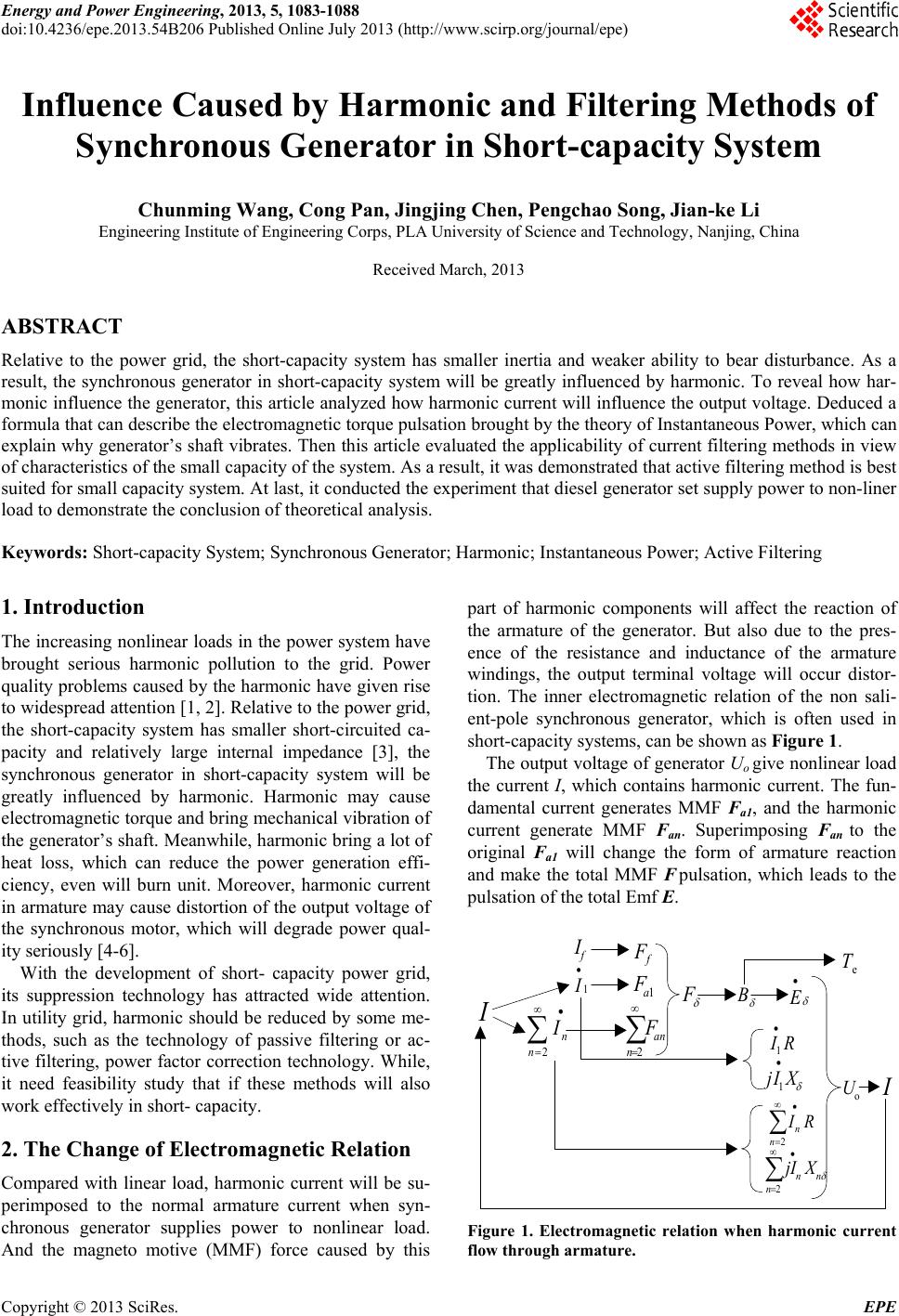 Energy and Power Engineering, 2013, 5, 1083-1088 doi:10.4236/epe.2013.54B206 Published Online July 2013 (http://www.scirp.org/journal/epe) Influence Caused by Harmonic and Filtering Methods of Synchronous Generator in Short-capacity System Chunming Wang, Cong Pan, Jingjing Chen, Pengchao Song, Jian-ke Li Engineering Institute of Engineering Corps, PLA University of Science and Technology, Nanjing, China Received March, 2013 ABSTRACT Relative to the power grid, the short-capacity system has smaller inertia and weaker ability to bear disturbance. As a result, the synchronous generator in short-capacity system will be greatly influenced by harmonic. To reveal how har- monic influence the generator, this article analyzed how harmonic current will influence the output voltage. Deduced a formula that can describe the electromagnetic torque pulsation brought by the theory of Instantaneous Power, which can explain why generator’s shaft vibrates. Then this article evaluated the applicability of current filtering methods in view of characteristics of the small capacity of the system. As a result, it was demonstrated that active filtering method is best suited for small capacity system. At last, it conducted the experiment that diesel generator set supply power to non-liner load to demonstrate the conclusion of theoretical analysis. Keywords: Short-capacity System; Synchronous Generator; Harmonic; Instantaneous Power; Active Filtering 1. Introduction The increasing nonlinear loads in the power system have brought serious harmonic pollution to the grid. Power quality problems caused by the harmonic have given rise to widespread attention [1, 2]. Relative to the power grid, the short-capacity system has smaller short-circuited ca- pacity and relatively large internal impedance [3], the synchronous generator in short-capacity system will be greatly influenced by harmonic. Harmonic may cause electromagnetic torque and bring mechanical vibration of the generator’s shaft. Meanwhile, harmonic bring a lot of heat loss, which can reduce the power generation effi- ciency, even will burn unit. Moreover, harmonic current in armature may cause distortion of the output voltage of the synchronous motor, which will degrade power qual- ity seriously [4-6]. With the development of short- capacity power grid, its suppression technology has attracted wide attention. In utility grid, harmonic should be reduced by some me- thods, such as the technology of passive filtering or ac- tive filtering, power factor correction technology. While, it need feasibility study that if these methods will also work effectively in short- capacity. 2. The Change of Electromagnetic Relation Compared with linear load, harmonic current will be su- perimposed to the normal armature current when syn- chronous generator supplies power to nonlinear load. And the magneto motive (MMF) force caused by this part of harmonic components will affect the reaction of the armature of the generator. But also due to the pres- ence of the resistance and inductance of the armature windings, the output terminal voltage will occur distor- tion. The inner electromagnetic relation of the non sali- ent-pole synchronous generator, which is often used in short-capacity systems, can be shown as Figure 1. The output voltage of generator Uo give nonlinear load the current I, which contains harmonic current. The fun- damental current generates MMF Fa1, and the harmonic current generate MMF Fan. Superimposing Fan to the original Fa1 will change the form of armature reaction and make the total MMF F pulsation, which leads to the pulsation of the total Emf E. E I 1 I RI 1 XIj 1 2n n RI 2n nn XjI 2n n I 2n an F 1a F f I f F F B o U I e T Figure 1. Electromagnetic relation when harmonic current flow through armature. Copyright © 2013 SciRes. EPE 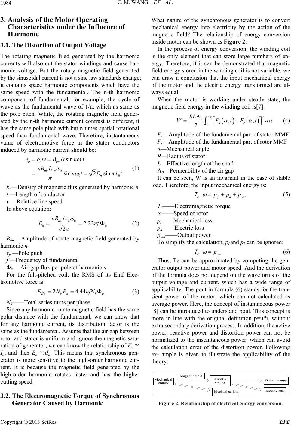 C. M. WANG ET AL. 1084 3. Analysis of the Motor Operating Characteristics under the Influence of Harmonic 3.1. The Distortion of Output Voltage The rotating magnetic filed generated by the harmonic currents will also cut the stator windings and cause har- monic voltage. But the rotary magnetic field generated by the sinusoidal current is not a sine law standards change; it contains space harmonic components which have the same speed with the fundamental. The n-th harmonic component of fundamental, for example, the cycle of wave as the fundamental wave of 1/n, which as same as the pole pitch. While, the rotating magnetic field gener- ated by the n-th harmonic current contrast is different, it has the same pole pitch with but n times spatial rotational speed than fundamental wave. Therefore, instantaneous value of electromotive force in the stator conductors induced by harmonic current should be: 0 0 00 sin sin2 sin nn nm nm p n eblvBlvnt nB lntE nt (1) bn—Density of magnetic flux generated by harmonic n l —Length of conductor v —Relative line speed In above equation: 02.22 2 nm p n nB l En n f (2) Bnm—Amplitude of rotate magnetic field generated by harmonic n τp —Pole pitch f —Frequency of fundamental Φn —Air-gap flux per pole of harmonic n For the full-pitched coil, the RMS of its Emf Elec- tromotive force is: 24.44 K nkn k ENE nfN n (3) Nk——Total series turns per phase Since any harmonic rotate magnetic field has the same polar distance with the fundamental, we can know that for any harmonic current, its distribution factor is the same as the fundamental. Assume that the air gap between rotor and stator is uniform and ignore the magnetic satu- ration of generator, we can know the relationship of Fn ∝ In, and then E n ∝ nIn. This means that synchronous gen- erator is more sensitive to the high-order harmonic cur- rent. It is because the magnetic field generated by the high-order harmonic rotates faster and has the higher cutting speed. 3.2. The Electromagnetic Torque of Synchronous Generator Caused by Harmonic What nature of the synchronous generator is to convert mechanical energy into electricity by the action of the magnetic field? The relationship of energy conversion inside motor can be shown as Figure 2. In the process of energy conversion, the winding coil is the only element that can store large numbers of en- ergy. Therefore, if it can be demonstrated that magnetic field energy stored in the winding coil is not variable, we can draw a conclusion that the input mechanical energy of the motor and the electric energy transformed are al- ways equal. When the motor is working under steady state, the magnetic field energy in the winding coil is[7]: 2 2 0 0,, 2sr RL WFtFt d (4) Fs—Amplitude of the fundamental part of stator MMF Fr—Amplitude of the fundamental part of rotor MMF α—Mechanical angle R—Radius of stator L—Effective length of the shaft Λ0—Permeability of the air gap It can be seen, W is an invariant in the case of stable load. Therefore, the input mechanical energy is: efh out Tppp (5) Te——Electromagnetic torque ω——Speed of rotor pf——Mechanical loss ph——Electric loss pout——Output power To simplify the calculation, pf and ph can be ignored: e out Tp (6) Thus, Te can be approximated by computing the gen- erator output power and motor speed. And the derivation of the formula does not depend on the waveforms of the output voltage and current, which has a wide range of applicability. The pout in formula (6) stands for the tran- sient power of the motor, which can not calculated as average power. Here, the concept of instantaneous power [8] can be introduced to understand pout. This concept is more in line with the original definition p=u*i, without extra secondary derivation process. In addition, the active power, reactive power and distortion power can not be normalized to the instantaneous power, which can avoid the calculation error of the distortion power. Following ex- ample is given to illustrate the applicability of the theory: Figure 2. Relationship of electrical energy conversion. Copyright © 2013 SciRes. EPE 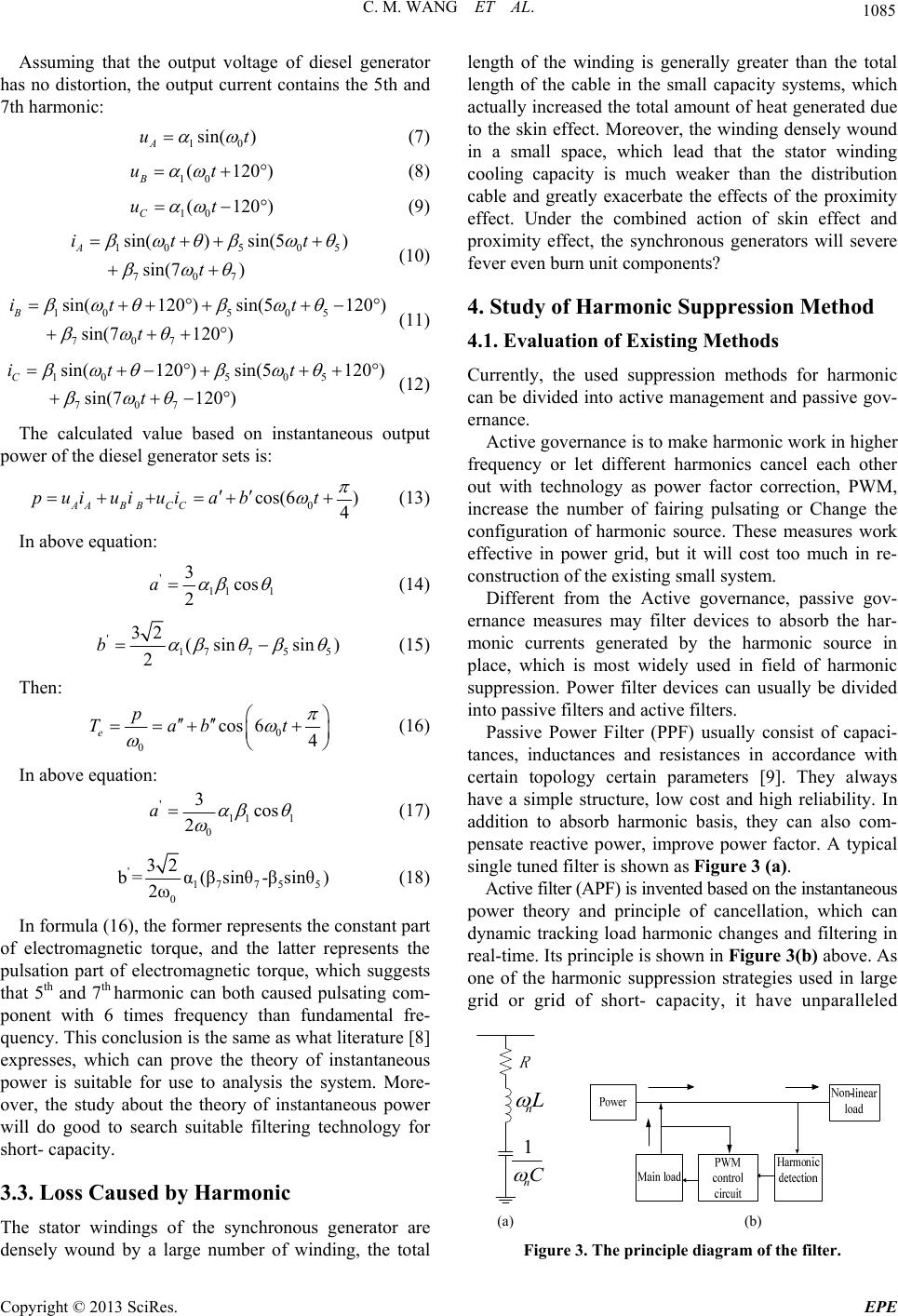 C. M. WANG ET AL. 1085 Assuming that the output voltage of diesel generator has no distortion, the output current contains the 5th and 7th harmonic: 10 sin( ) A ut (7) 10 (120 B ut) (8) 10 (120 ) C ut 5 (9) 105 0 707 sin() sin(5) sin(7) A it t t (10) 105 05 707 sin(120 )sin(5120 ) sin(7120) B it t t (11) 105 05 707 sin(120 )sin(5120 ) sin(7120) C it t t (12) The calculated value based on instantaneous output power of the diesel generator sets is: 0 cos(6 ) 4 AAB BCC puiui uiabt (13) In above equation: ' 11 1 3cos 2 a (14) ' 177 55 32 (sin sin) 2 b (15) Then: 0 0 cos 64 e p Tab t (16) In above equation: ' 11 1 0 3cos 2 a (17) ' 1775 5 0 32 b= α(βsinθ-βsinθ) 2ω (18) In formula (16), the former represents the constant part of electromagnetic torque, and the latter represents the pulsation part of electromagnetic torque, which suggests that 5th and 7th harmonic can both caused pulsating com- ponent with 6 times frequency than fundamental fre- quency. This conclusion is the same as what literature [8] expresses, which can prove the theory of instantaneous power is suitable for use to analysis the system. More- over, the study about the theory of instantaneous power will do good to search suitable filtering technology for short- capacity. 3.3. Loss Caused by Harmonic The stator windings of the synchronous generator are densely wound by a large number of winding, the total length of the winding is generally greater than the total length of the cable in the small capacity systems, which actually increased the total amount of heat generated due to the skin effect. Moreover, the winding densely wound in a small space, which lead that the stator winding cooling capacity is much weaker than the distribution cable and greatly exacerbate the effects of the proximity effect. Under the combined action of skin effect and proximity effect, the synchronous generators will severe fever even burn unit components? 4. Study of Harmonic Suppression Method 4.1. Evaluation of Existing Methods Currently, the used suppression methods for harmonic can be divided into active management and passive gov- ernance. Active governance is to make harmonic work in higher frequency or let different harmonics cancel each other out with technology as power factor correction, PWM, increase the number of fairing pulsating or Change the configuration of harmonic source. These measures work effective in power grid, but it will cost too much in re- construction of the existing small system. Different from the Active governance, passive gov- ernance measures may filter devices to absorb the har- monic currents generated by the harmonic source in place, which is most widely used in field of harmonic suppression. Power filter devices can usually be divided into passive filters and active filters. Passive Power Filter (PPF) usually consist of capaci- tances, inductances and resistances in accordance with certain topology certain parameters [9]. They always have a simple structure, low cost and high reliability. In addition to absorb harmonic basis, they can also com- pensate reactive power, improve power factor. A typical single tuned filter is shown as Figure 3 (a). Active filter (APF) is invented based on the instantaneous power theory and principle of cancellation, which can dynamic tracking load harmonic changes and filtering in real-time. Its principle is shown in Figure 3(b) above. As one of the harmonic suppression strategies used in large grid or grid of short- capacity, it have unparalleled n L 1 n C (a) (b) Figure 3. The principle diagram of the filter. Copyright © 2013 SciRes. EPE 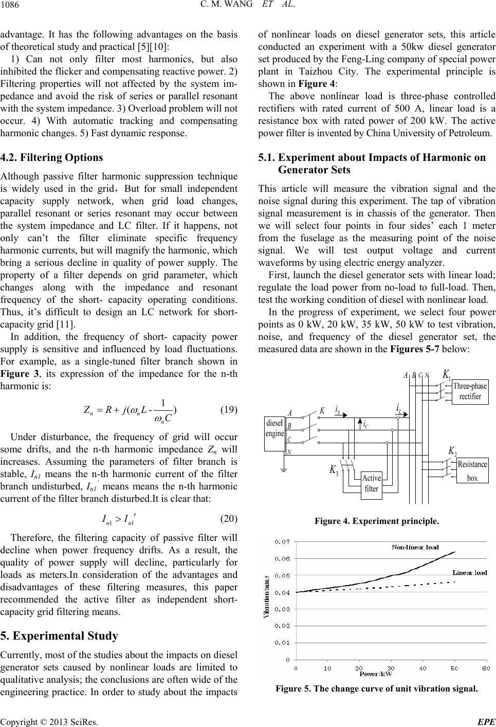 C. M. WANG ET AL. 1086 advantage. It has the following advantages on the basis of theoretical study and practical [5][10]: 1) Can not only filter most harmonics, but also inhibited the flicker and compensating reactive power. 2) Filtering properties will not affected by the system im- pedance and avoid the risk of series or parallel resonant with the system impedance. 3) Overload problem will not occur. 4) With automatic tracking and compensating harmonic changes. 5) Fast dynamic response. 4.2. Filtering Options Although passive filter harmonic suppression technique is widely used in the grid,But for small independent capacity supply network, when grid load changes, parallel resonant or series resonant may occur between the system impedance and LC filter. If it happens, not only can’t the filter eliminate specific frequency harmonic currents, but will magnify the harmonic, which bring a serious decline in quality of power supply. The property of a filter depends on grid parameter, which changes along with the impedance and resonant frequency of the short- capacity operating conditions. Thus, it’s difficult to design an LC network for short- capacity grid [11]. In addition, the frequency of short- capacity power supply is sensitive and influenced by load fluctuations. For example, as a single-tuned filter branch shown in Figure 3, its expression of the impedance for the n-th harmonic is: 1 (- nn n ZRjL C ) 1 (19) Under disturbance, the frequency of grid will occur some drifts, and the n-th harmonic impedance Zn will increases. Assuming the parameters of filter branch is stable, In1 means the n-th harmonic current of the filter branch undisturbed, In1 ’ means means the n-th harmonic current of the filter branch disturbed.It is clear that: 1nn I I (20) Therefore, the filtering capacity of passive filter will decline when power frequency drifts. As a result, the quality of power supply will decline, particularly for loads as meters.In consideration of the advantages and disadvantages of these filtering measures, this paper recommended the active filter as independent short- capacity grid filtering means. 5. Experimental Study Currently, most of the studies about the impacts on diesel generator sets caused by nonlinear loads are limited to qualitative analysis; the conclusions are often wide of the engineering practice. In order to study about the impacts of nonlinear loads on diesel generator sets, this article conducted an experiment with a 50kw diesel generator set produced by the Feng-Ling company of special power plant in Taizhou City. The experimental principle is shown in Figure 4: The above nonlinear load is three-phase controlled rectifiers with rated current of 500 A, linear load is a resistance box with rated power of 200 kW. The active power filter is invented by China University of Petroleum. 5.1. Experiment about Impacts of Harmonic on Generator Sets This article will measure the vibration signal and the noise signal during this experiment. The tap of vibration signal measurement is in chassis of the generator. Then we will select four points in four sides’ each 1 meter from the fuselage as the measuring point of the noise signal. We will test output voltage and current waveforms by using electric energy analyzer. First, launch the diesel generator sets with linear load; regulate the load power from no-load to full-load. Then, test the working condition of diesel with nonlinear load. In the progress of experiment, we select four power points as 0 kW, 20 kW, 35 kW, 50 kW to test vibration, noise, and frequency of the diesel generator set, the measured data are shown in the Figures 5-7 below: A B C N K L i S i C i 1 K A B C N 2 K 3 K Figure 4. Experiment principle. Figure 5. The change curve of unit vibration signal. Copyright © 2013 SciRes. EPE 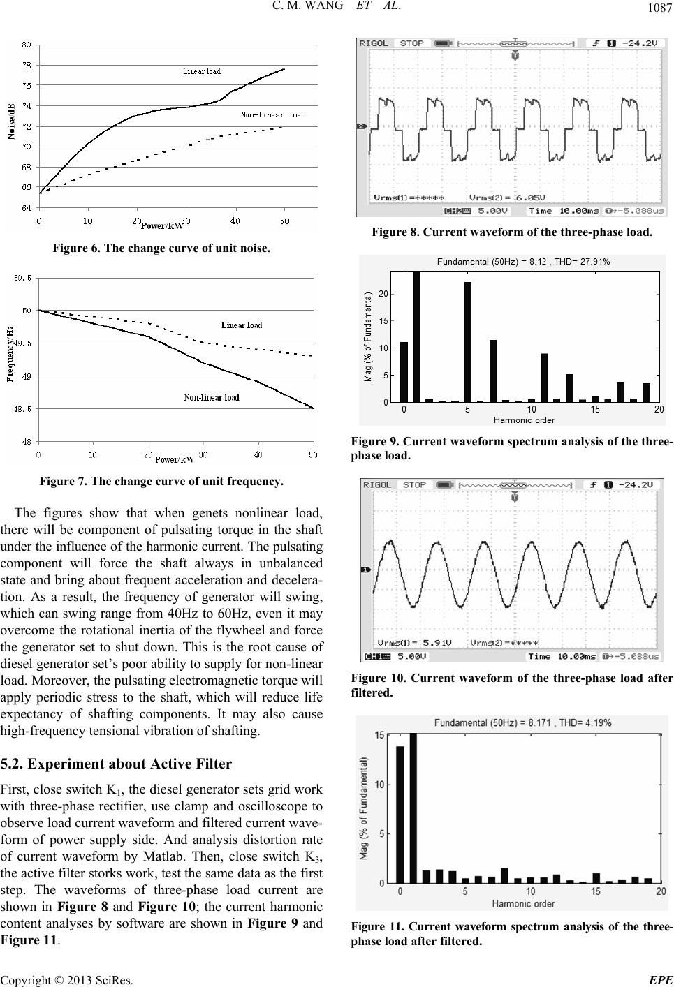 C. M. WANG ET AL. 1087 Figure 6. The change curve of unit noise. Figure 7. The change curve of unit frequency. The figures show that when genets nonlinear load, there will be component of pulsating torque in the shaft under the influence of the harmonic current. The pulsating component will force the shaft always in unbalanced state and bring about frequent acceleration and decelera- tion. As a result, the frequency of generator will swing, which can swing range from 40Hz to 60Hz, even it may overcome the rotational inertia of the flywheel and force the generator set to shut down. This is the root cause of diesel generator set’s poor ability to supply for non-linear load. Moreover, the pulsating electromagnetic torque will apply periodic stress to the shaft, which will reduce life expectancy of shafting components. It may also cause high-frequency tensional vibration of shafting. 5.2. Experiment about Active Filter First, close switch K1, the diesel generator sets grid work with three-phase rectifier, use clamp and oscilloscope to observe load current waveform and filtered current wave- form of power supply side. And analysis distortion rate of current waveform by Matlab. Then, close switch K3, the active filter storks work, test the same data as the first step. The waveforms of three-phase load current are shown in Figure 8 and Figure 10; the current harmonic content analyses by software are shown in Figure 9 and Figure 11. Figure 8. Current waveform of the three-phase load. Figure 9. Current waveform spectrum analysis of the three- phase load. Figure 10. Current waveform of the three-phase load after filtered. Figure 11. Current waveform spectrum analysis of the three- phase load after filtered. Copyright © 2013 SciRes. EPE 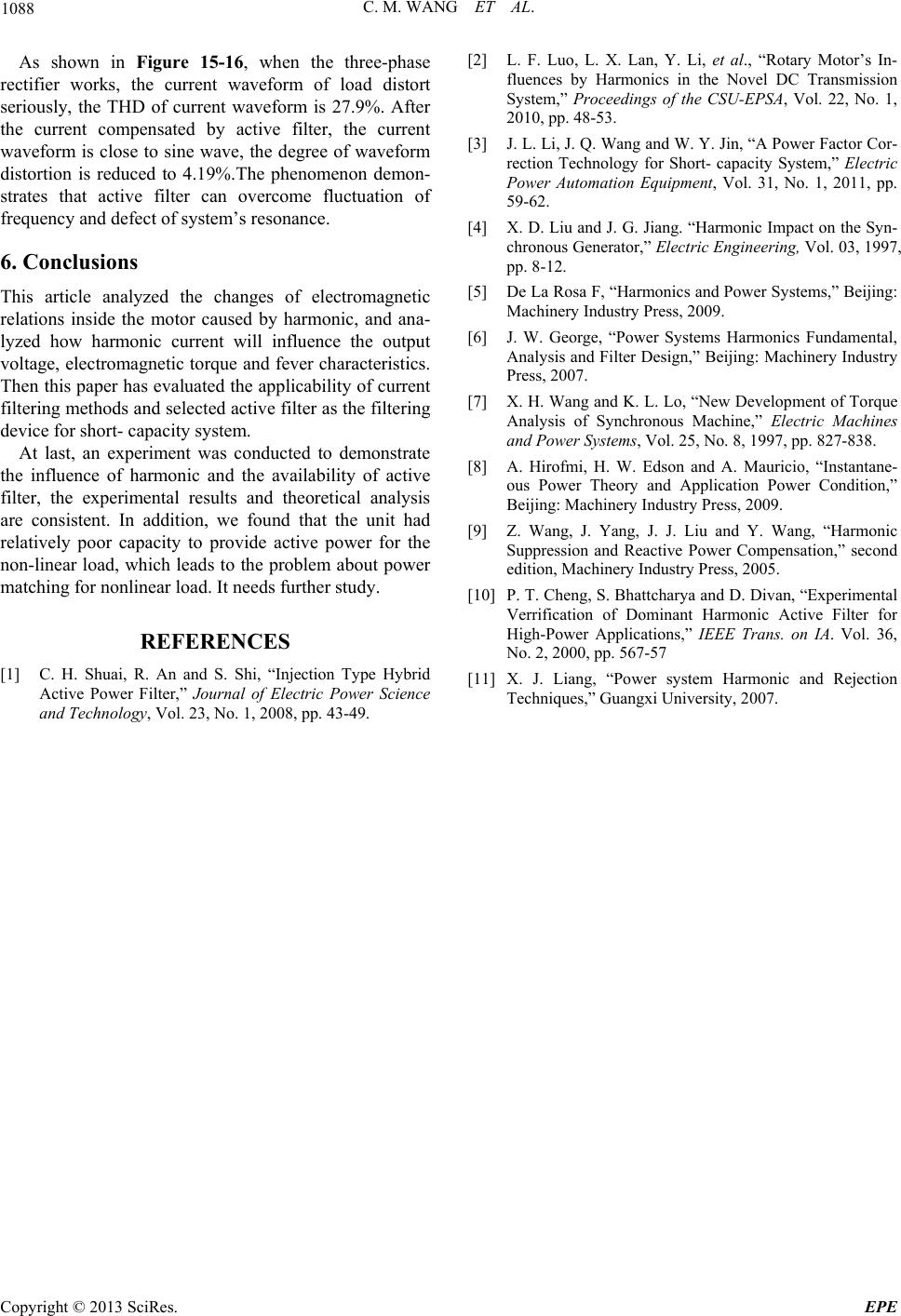 C. M. WANG ET AL. Copyright © 2013 SciRes. EPE 1088 As shown in Figure 15-16, when the three-phase rectifier works, the current waveform of load distort seriously, the THD of current waveform is 27.9%. After the current compensated by active filter, the current waveform is close to sine wave, the degree of waveform distortion is reduced to 4.19%.The phenomenon demon- strates that active filter can overcome fluctuation of frequency and defect of system’s resonance. 6. Conclusions This article analyzed the changes of electromagnetic relations inside the motor caused by harmonic, and ana- lyzed how harmonic current will influence the output voltage, electromagnetic torque and fever characteristics. Then this paper has evaluated the applicability of current filtering methods and selected active filter as the filtering device for short- capacity system. At last, an experiment was conducted to demonstrate the influence of harmonic and the availability of active filter, the experimental results and theoretical analysis are consistent. In addition, we found that the unit had relatively poor capacity to provide active power for the non-linear load, which leads to the problem about power matching for nonlinear load. It needs further study. REFERENCES [1] C. H. Shuai, R. An and S. Shi, “Injection Type Hybrid Active Power Filter,” Journal of Electric Power Science and Technology, Vol. 23, No. 1, 2008, pp. 43-49. [2] L. F. Luo, L. X. Lan, Y. Li, et al., “Rotary Motor’s In- fluences by Harmonics in the Novel DC Transmission System,” Proceedings of the CSU-EPSA, Vol. 22, No. 1, 2010, pp. 48-53. [3] J. L. Li, J. Q. Wang and W. Y. Jin, “A Power Factor Cor- rection Technology for Short- capacity System,” Electric Power Automation Equipment, Vol. 31, No. 1, 2011, pp. 59-62. [4] X. D. Liu and J. G. Jiang. “Harmonic Impact on the Syn- chronous Generator,” Electric Engineering, Vol. 03, 1997, pp. 8-12. [5] De La Rosa F, “Harmonics and Power Systems,” Beijing: Machinery Industry Press, 2009. [6] J. W. George, “Power Systems Harmonics Fundamental, Analysis and Filter Design,” Beijing: Machinery Industry Press, 2007. [7] X. H. Wang and K. L. Lo, “New Development of Torque Analysis of Synchronous Machine,” Electric Machines and Power Systems, Vol. 25, No. 8, 1997, pp. 827-838. [8] A. Hirofmi, H. W. Edson and A. Mauricio, “Instantane- ous Power Theory and Application Power Condition,” Beijing: Machinery Industry Press, 2009. [9] Z. Wang, J. Yang, J. J. Liu and Y. Wang, “Harmonic Suppression and Reactive Power Compensation,” second edition, Machinery Industry Press, 2005. [10] P. T. Cheng, S. Bhattcharya and D. Divan, “Experimental Verrification of Dominant Harmonic Active Filter for High-Power Applications,” IEEE Trans. on IA. Vol. 36, No. 2, 2000, pp. 567-57 [11] X. J. Liang, “Power system Harmonic and Rejection Techniques,” Guangxi University, 2007. |