Paper Menu >>
Journal Menu >>
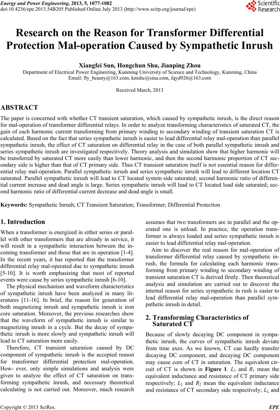 Energy and Power Engineering, 2013, 5, 1077-1082 doi:10.4236/epe.2013.54B205 Published Online July 2013 (http://www.scirp.org/journal/epe) Research on the Reason for Transformer Differential Protection Mal-operation Caused by Sympathetic Inrush Xiangfei Sun, Hongchun Shu, Jianping Zhou Department of Electrical Power Engineering, Kunming University of Science and Technology, Kunming, China Email: fly_beauty@163.com, kmshc@sina.com, fqyd926@163.com Received March, 2013 ABSTRACT The paper is concerned with whether CT transient saturation, which caused by sympathetic inrush, is the direct reason for mal-operation of transformer differential relays. In order to analyze transforming characteristics of saturated CT, the gain of each harmonic current transforming from primary winding to secondary winding of transient saturation CT is calculated. Based on the fact that series sympathetic inrush is easier to lead differential relay mal-operation than parallel sympathetic inrush, the effect of CT saturation on differential relay in the case of both parallel sympathetic inrush and series sympathetic inrush are investigated respectively. Theory analysis and simulation show that higher harmonic will be transferred by saturated CT more easily than lower harmonic, and then the second harmonic proportion of CT sec- ondary side is higher than that of CT primary side. Thus CT transient saturation itself is not essential reason for differ- ential relay mal-operation. Parallel sympathetic inrush and series sympathetic inrush will lead to different location CT saturated. Parallel sympathetic inrush will lead to CT located system side saturated; second h armonic ratio of differen- tial current increase and dead angle is large. Series sympathetic inrush will lead to CT located load side saturated; sec- ond harmonic ratio of differential current decrease and dead angle is small. Keywords: Sympathetic Inrush; CT Transient Saturation; Transformer; Differential Protection 1. Introduction When a tran sformer is energize d in either ser ies or para l- lel with other transformers that are already in service, it will result in a sympathetic interaction between the in- coming transformer and those that are in operation [1-4]. In the recent years, it has reported that the transformer differential relay mal-operated due to sympathetic inrush [5-10]. It is worth emphasizing that most of reported events were cause by series sympathetic inrush [6-10]. The physical mechanism and waveform characteristics of sympathetic inrush have been analyzed in many lit- eratures [11-16]. In brief, the reason for generation of both magnetizing inrush and sympathetic inrush is iron core saturation. Moreover, the previous researches show that the waveform of sympathetic inrush is similar to magnetizing inrush in a cycle. But the decay of sympa- thetic inrush is more slowly and sympathetic inrush will lead to CT saturation more easily. Therefore, CT transient saturation caused by DC component of sympathetic inrush is the accepted reason for transformer differential protection mal-operation. How- ever, only simple simulations and analysis were given to analyze the effect of CT saturation on trans- forming sympathetic inrush, and necessary theoretical calculating is not carried out. Moreover, much research assumes that two transformers are in parallel and the op- erated one is unload. In practice, the operation trans- former is always loaded and series sympathetic inrush is easier to lead differential relay mal-operation. Aim to discover the real reason for mal-operation of transformer differential relay caused by sympathetic in- rush, the formula for calculating each harmonic trans- forming from primary winding to secondary winding of transient saturation CT is derived firstly. Then theo retical analysis and simulation are carried out to discover the internal reason for series sympathetic in rush is easier to lead differential relay mal-operation than parallel sym- pathetic inrush in detail. 2. Transforming Characteristics of Saturated CT Because of slowly decaying DC component in sympa- thetic inrush, the curves of sympathetic inrush deviate from time axes. As we known, CT can hardly transfer decaying DC component, and decaying DC component may cause core of CT in saturation. The equivalent cir- cuit of CT is shown in Figure 1. L1 and R1 mean the equivalent inductance and resistance of CT primary side respectively; L2 and R2 mean the equivalent inductance and resistance of CT secondary side respectively; LL and Copyright © 2013 SciRes. EPE 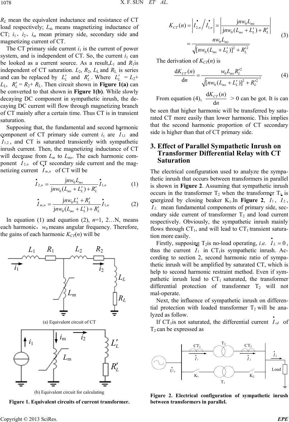 X. F. SUN ET AL. 1078 RL mean the equivalent inductance and resistance of CT load respectively; Lm means magnetizing inductance of CT; i1、i2、im mean primary side, secondary side and magnetizing current of CT. The CT primary side current i1 is the current of power system, and is independent of CT. So, the current i1 can be looked as a current source. As a result,L1 and R1is independent of CT saturation. L2, R2, LL and RL is series and can be replaced by L L and L R. Where L L = L2+ LL, L R= R2+ RL. Then circuit shown in Figure 1(a) can be conver ted to that shown in Figure 1(b). While slowly decaying DC component in sympathetic inrush, the de- caying DC current will flow through magnetizing branch of CT mainly after a certain time. Thus CT is in transient saturation. Supposing that, the fundamental and second harmonic component of CT primary side current i1 are 1,1 I and 1,2 I , and CT is saturated transiently with sympathetic inrush current. Then, the magnetizing inductance of CT will decrease from Lm to Lms. The each harmonic com- ponent 2,n I of CT secondary side current and the mag- netizing curre n t ,mn I of CT will be 0 2, 1, 0 j j( ) ms n ms LL nw Ln I I nw LLR (1) 0 , 0 j j( ) LL mn n ms LL nw LR1, I I nw LLR (2) In equation (1) and equation (2), n=1, 2…N, means each harmonic,w0 means angular frequency. Therefore, the gains of each harmonic KCT(n) will be R 1 L 1 L 2 R 2 L L R L L m i 1 i 2 (a) Equivalent circuit of CT L L L m L R i 2 i 1 i m (b) Equivalent circuit for calculating Figure 1. Equivalent circuits of current transformer. 0 2, 1,0 0 22 0 j () j( ) [( )] ms CTn nms LL ms ms LL nw L Kn IInw LLR nw L nw LLR (3) The derivat i on of KCT(n) is 2 03 22 0 d() d[( )] CTms L ms LL Kn wLR nnw LLR (4) From equation (4), d( d CT ) K n n > 0 can be got. It is can be seen that higher harmonic will be transferred by satu- rated CT more easily than lower harmonic. This implies that the second harmonic proportion of CT secondary side is higher than that of CT primary side. 3. Effect of Parallel Sympathetic Inrush on Transformer Differential Relay with CT Saturation The electrical configuration used to analyze the sympa- thetic inrush that occurs be tween transformers in parallel is shown in Figure 2. Assuming that sympathetic inrush occurs in the transformer T2 when the transformer T1 is energized by closing beaker K1.In Figure 2, 1 I , 2 I , L I mean fundamental components of primary side, sec- ondary side current of transformer T2 and load current respectively. Obviously, the sympathetic inrush mainly flows through CT1, and will lead to CT1 transient satura- tion more easily. Firstly, supposing T2is no-load operating, i.e. 0 L I , thus the current 1 I in CT1is sympathetic inrush. Ac- cording to section 2, second harmonic ratio of sympa- thetic inrush will be amplified by saturated CT, which is help to second harmonic restraint method. Even if sym- pathetic inrush lead to CT1 saturated, the transformer differential protection of transformer T2 will not mal-operate. Next, the influence of sympathetic inrush on differen- tial protection with loaded transformer T2 will be ana- lyzed as follow. If CT1is not saturated, the differential current cd I of T2 can be expressed as CT 1 CT 2 T 2 T 1 Load K 1 K 2 1 I 2 I b U L I Figure 2. Electrical configuration of sympathetic inrush between tr ansfor mers in parallel. Copyright © 2013 SciRes. EPE 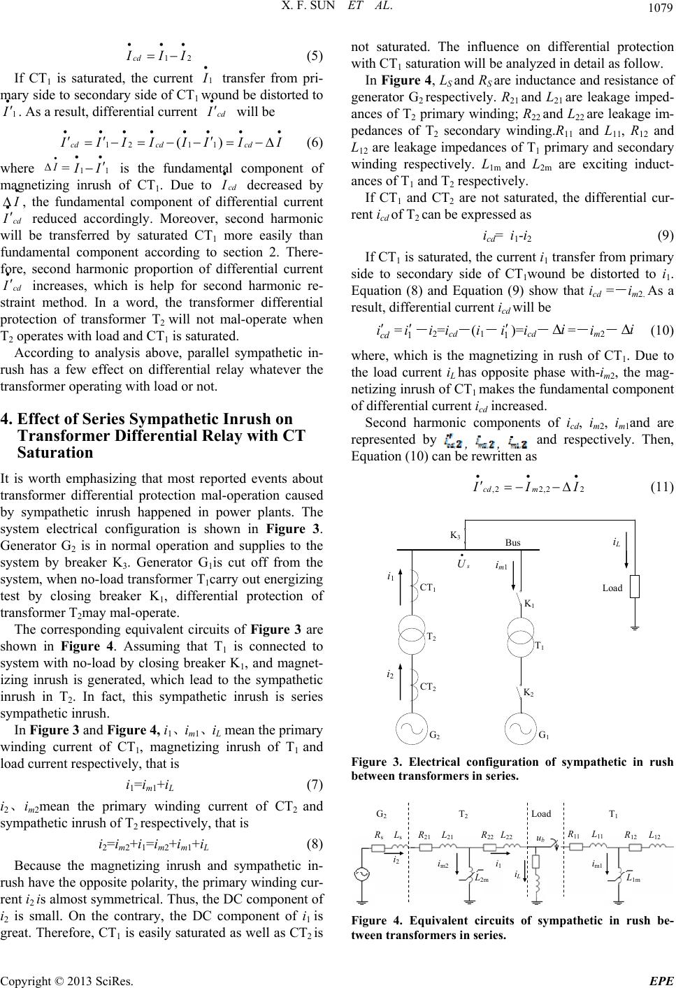 X. F. SUN ET AL. 1079 12cd I II (5) If CT1 is saturated, the current 1 I transfer from pri- mary side to seco ndary side of CT1 wound be d istorted to 1 I . As a result, differential current cd I will be 121 1 () cd cdcd I II IIIII (6) where I =11 I I is the fundamental component of magnetizing inrush of CT1. Due to cd I decreased by I cd , the fundamental component of differential current I cd reduced accordingly. Moreover, second harmonic will be transferred by saturated CT1 more easily than fundamental component according to section 2. There- fore, second harmonic proportion of differential current I increases, which is help for second harmonic re- straint method. In a word, the transformer differential protection of transformer T2 will not mal-operate when T2 operates with load and CT1 is saturated. According to analysis above, parallel sympathetic in- rush has a few effect on differential relay whatever the transformer operating with load or not. 4. Effect of Series Sympathetic Inrush on Transformer Differential Relay with CT Saturation It is worth emphasizing that most reported events about transformer differential protection mal-operation caused by sympathetic inrush happened in power plants. The system electrical configuration is shown in Figure 3. Generator G2 is in normal operation and supplies to the system by breaker K3. Generator G1is cut off from the system, when no-load transformer T1carry out energizing test by closing breaker K1, differential protection of transformer T2may mal-operate. The corresponding equivalent circuits of Figure 3 are shown in Figure 4. Assuming that T1 is connected to system with no-load by closing breaker K1, and magnet- izing inrush is generated, which lead to the sympathetic inrush in T2. In fact, this sympathetic inrush is series sympathetic inrush. In Figure 3 and Fi g u re 4, i1、im1、iL mean the primary winding current of CT1, magnetizing inrush of T1 and load current respectively, that is i1=im1+iL (7) i2、im2mean the primary winding current of CT2 and sympathetic inrush of T2 respectively, that is i2=im2+i1=im2+im1+iL (8) Because the magnetizing inrush and sympathetic in- rush have the opposite polarity, the primary winding cur- rent i2 is almost symmetrical. Thus, the DC component of i2 is small. On the contrary, the DC component of i1 is great. Therefore, CT1 is easily saturated as well as CT2 is not saturated. The influence on differential protection with CT1 saturation will be analyzed in detail as follow. In Figure 4, LS and RS are inductance and resistance of generator G2 respectively. R21 and L21 are leakage imped- ances of T2 primary winding; R22 and L22 are leakage im- pedances of T2 secondary winding.R11 and L11, R12 and L12 are leakage impedances of T1 primary and secondary winding respectively. L1m and L2m are exciting induct- ances of T1 and T2 respectively. If CT1 and CT2 are not saturated, the differential cur- rent icd of T2 can be expressed as icd= i1-i2 (9) If CT1 is saturated, the current i1 transfer from primary side to secondary side of CT1wound be distorted to i1. Equation (8) and Equation (9) show that icd =-im2. As a result, differential current icd will be cd i =1 i -i2=icd-(i1-1 i )=icd-=-im2- ii (10) where, which is the magnetizing in rush of CT1. Due to the load current iL has opposite phase with-im2, the mag- netizing inrush of CT1 makes the fundamental component of differential current icd increased. Second harmonic components of icd, i m2, i m1and are represented by , , and respectively. Then, Equation (10) can be rewritten as ,2 2,2cd m2 I II (11) T2 T1 CT1 G2G1 CT2 K2 K1 K3 i 2 i L i m1 i 1 s U Bus Load Figure 3. Electrical configuration of sympathetic in rush between transformers in series. L 22 L 11 L 12 L 21 L 1m L 2m L s R s R 21 R 11 R 12 R 22 i 2 Load i 1 i L i m2 i m1 G 2 T 2 T 1 u b Figure 4. Equivalent circuits of sympathetic in rush be- tween transformers in series. Copyright © 2013 SciRes. EPE 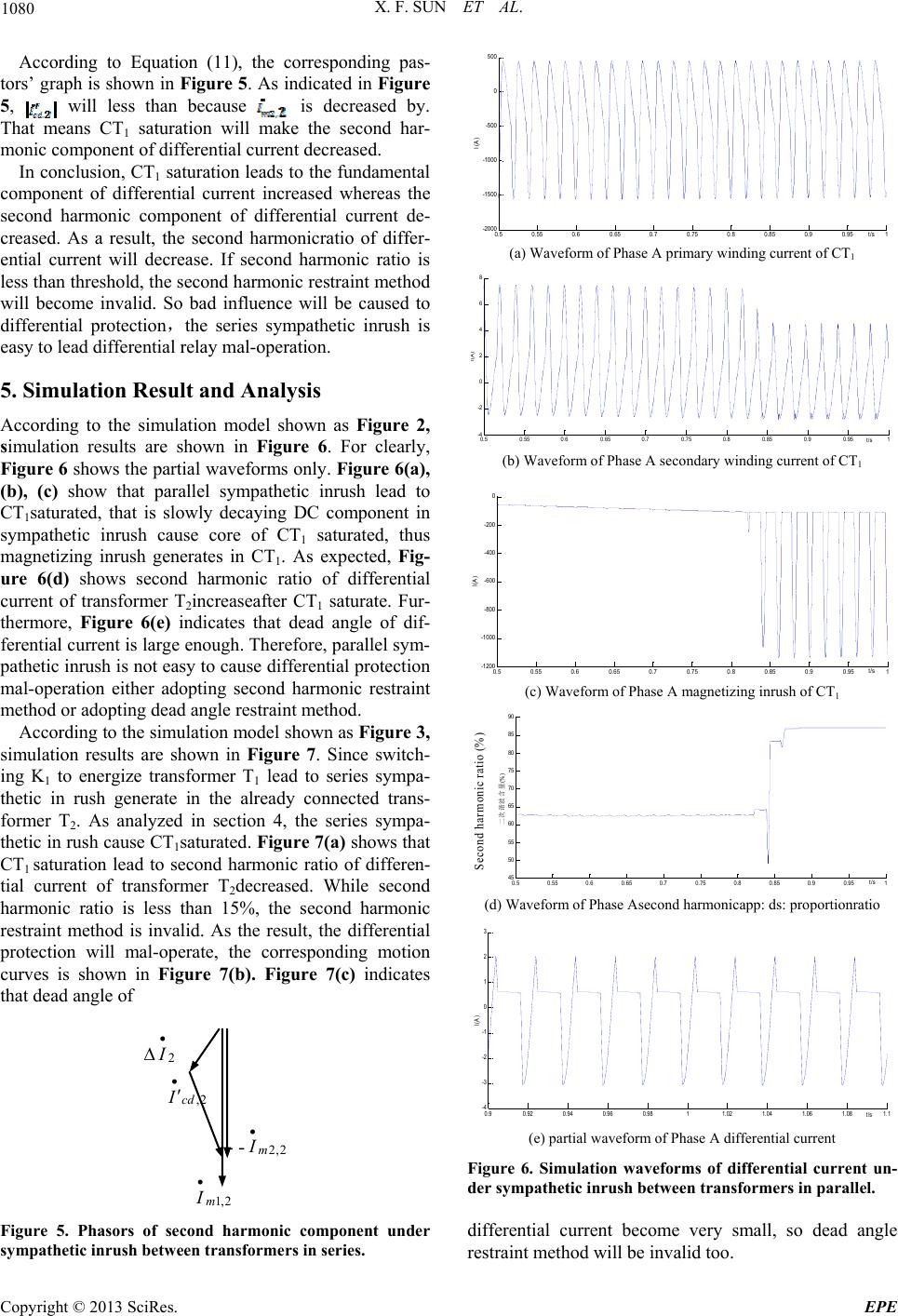 X. F. SUN ET AL. 1080 According to Equation (11), the corresponding pas- tors’ gr aph is shown in Figure 5. As indicated in Figure 5, will less than because is decreased by. That means CT1 saturation will make the second har- monic component of differential current decreased. 500 In conclusion, CT1 saturation leads to the fundamental component of differential current increased whereas the second harmonic component of differential current de- creased. As a result, the second harmonicratio of differ- ential current will decrease. If second harmonic ratio is less than threshold, the second harmonic restraint method will become invalid. So bad influence will be caused to differential protection,the series sympathetic inrush is easy to lead differential relay mal-operation. 5. Simulation Result and Analysis According to the simulation model shown as Figure 2, simulation results are shown in Figure 6. For clearly, Figure 6 shows the partial waveforms only. Figure 6(a), (b), (c) show that parallel sympathetic inrush lead to CT1saturated, that is slowly decaying DC component in sympathetic inrush cause core of CT1 saturated, thus magnetizing inrush generates in CT1. As expected, Fig- ure 6(d) shows second harmonic ratio of differential current of transformer T2increaseafter CT1 saturate. Fur- thermore, Figure 6(e) indicates that dead angle of dif- ferential current is large enough. Ther efore, parallel sy m- pathetic inrush is not easy to cause differential protection mal-operation either adopting second harmonic restraint method or adopting dead angle restraint method. According to the simulation model shown as Figure 3, simulation results are shown in Figure 7. Since switch- ing K1 to energize transformer T1 lead to series sympa- thetic in rush generate in the already connected trans- former T2. As analyzed in section 4, the series sympa- thetic in rush cause CT1saturated. Figure 7(a) shows that CT1 saturation lead to second harmonic ratio of differen- tial current of transformer T2decreased. While second harmonic ratio is less than 15%, the second harmonic restraint method is invalid. As the result, the differential protection will mal-operate, the corresponding motion curves is shown in Figure 7(b). Figure 7(c) indicates that dead angle of 2,1m I - - 2,2m I 2,cd I 2 I Figure 5. Phasors of second harmonic component under sympathetic inrush between transformers in series. -1500 -1000 -500 0 I(A) 0.5 -2000 0.550.60.65 0.70.75 0.8 0.85 0.9 0.95 t/s 1 (a) Waveform of Phase A primary winding current of CT1 0.50.55 0.60.65 0.70.750.8 0.85 0.90.95 1 -4 -2 0 2 4 6 8 I(A) t/s (b) Waveform of Phase A secondary winding current of CT1 0.5 0.55 0.6 0.650.7 0.750.8 0.85 0.9 0.951 -1200 -1000 -800 -600 -400 -200 0 I(A) t/s (c) Waveform of Phase A magnetizing inrush of CT1 0.5 0.55 0.6 0.65 0.70.75 0.8 0.85 0.90.951 45 50 55 60 65 70 75 80 85 90 二次谐波含量 (%) t/s Se co nd ha rmonic ratio (% ) (d) Waveform o f P has e A sec ond harmonicapp : ds: proportionratio 0.90.92 0.94 0.96 0.9811.02 1.04 1.06 1.081.1 -4 -3 -2 -1 0 1 2 3 I(A) t/s (e) partial waveform of Phase A differential current Figure 6. Simulation waveforms of differential current un- der sympathetic inrush between transformers in parallel. differential current become very small, so dead angle restraint method will be invalid too. Copyright © 2013 SciRes. EPE 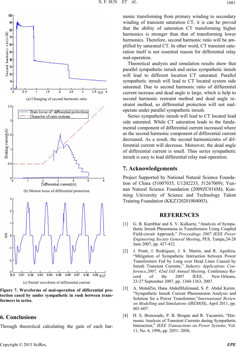 X. F. SUN ET AL. 1081 (a) Changing of second harmonic ratio (b) Motion locus of differential protection (c) Partial waveform of differential current Figure 7. Waveforms of mal-operation of differential pro- tection cased by under sympathetic in rush between trans- formers in series. 6. Conclusions Through theoretical calculating the gain of each har- monic transforming from primary winding to secondary winding of transient saturation CT, it is can be proved that the ability of saturation CT transforming higher harmonics is stronger than that of transforming lower harmonics. Therefore, second harmonic ratio will be am- plified by saturated CT. In other word, CT transient satu- ration itself is not essential reason for differential relay mal-operation. Theoretical analysis and simulation results show that parallel sympathetic inrush and series sympathetic inrush will lead to different location CT saturated. Parallel sympathetic inrush will lead to CT located system side saturated. Due to second harmonic ratio of differential current increase and dead angle is large, which is help to second harmonic restraint method and dead angle re- straint method, so differential protection will not mal- operate under parallel sympathetic inrush. Series sympathetic inrush will lead to CT located load side saturated. While CT saturation leads to the funda- mental component of differential current increased where as the second harmonic component of differential current decreased. As a result, the second harmonicratio of dif- ferential current will decrease. Moreover, the dead angle of differential current is small. Thus series sympathetic inrush is easy to lead differential relay mal-operation. 7. Acknowledgements Project Supported by National Natural Science Founda- tion of China (51007035, U1202233, 51267009); Yun- nan Natural Science Foundation (2009ZC016M); Kun- ming University of Science and Technology Talent Training Foundation (KKZ320201004003). REFERENCES [1] G. B. Kumbhar and S. V. Kulkarni, “Analysis of Sympa- thetic Inrush Phenomena in Transformers Using Coupled Field-circuit Approach,” Proceedings 2007 IEEE Power Engineering Society General Meeting, PES, Tampa,24-28 June 2007, pp. 427-432. [2] J. Pontt, J. Rodriguez, J. S. Martin, and R. Aguilera, “Mitigation of Sympathetic Interaction between Power Transformers Fed by Long over Head Lines Caused by Inrush Transient Currents,” Industry Applications Con- ference,2007, 42nd IAS Annual Meeting, Conference Re- cord of the 2007 IEEE, New Orleans, 23-27 September 2007, pp. 1360-1363, 2007. [3] A. MohdZin, Hana AbdullHalimand, S. P. Abdul Karim. “Sympathetic Inrush Current Phenomenon Analysis and Solution for a Power Transformer,”International Review on Modelling and Simulations (IREMOS), April 2011, pp. 601-607. [4] H. S. Bronzeado, P. B. Brogan and R. Yacamini, “Har- monic Analysis of Transient Currents during Sympathetic Interaction,” IEEE Transactions on Power Systems, Vol. 11, No. 4, 1996, pp. 2051- 2056. Copyright © 2013 SciRes. EPE  X. F. SUN ET AL. Copyright © 2013 SciRes. EPE 1082 doi:10.1109/59.544684 [5] Y. B. Zhou and L. Cao, “Inspection and Analysis of a Maloperation of Transformer Differential Protection and Its Preventive Measures,” Power Systems Technology, Vol.25, No. 20, 2001, pp. 71-74. [6] G. W. Yu, D. Q. Bi, Z. G. Wang and etc, “Phenomenon of Sympathetic Inrush and Analysis of an Example,” Automation of Electric Power Systems, Vol. 29, No. 6, 2005, pp.20-23. [7] D. J. Li, W. J. Wang and D. Q. Bi, “Analy sis of Transient Saturation and Sympathetic Inrush of Transformers,” High Voltage Apparatus, Vol. 41, No.1, 2005, pp.12-15. [8] L. Wei, T. Zheng, G. G. Wang and etc, “Synthetic Analy- sis on the Causes of Mal-operation and Preventive Meas- ures of Transformer Differential Protection,” Power Sys- tem Protection and Control, Vol. 36, No. 19, 2008, pp.40-43. [9] J. H. Wang and J. Q. Li, “The Analysis of a Misoperation of Differential Protection of Transformer,” Hydropower and New Energy, Vol. 6, 2011, pp.32-34. [10] S. F. Huang, J. Gu, T. Zheng and etc, “Mal-operation of Transformer Differential Protection with Inner Bridge Connection and Counter measure,” High Voltage Engi- neering, Vol.37, No.12, 2011, pp.3099-3106. [11] D. Q. Bi, X. H. Wang, D. J. Li and etc, “Theory Analysis of the Sympathetic Inrush in Operating Transformers,” Automation of Electric Power System, Vol. 29, No.6, 2005, pp.1-8. [12] Y. B. Yuan, D. J. Li and Y. P. Lu, “Physical Mechanism of Sympathetic Inrush of Transformer and Its Influence on Differential Protection,” Automation of Electric Power Systems, Vol.29, No.6, 2005, pp.9-14. [13] T. Zheng and P. Zhao, “Analysis of Influence Factors of Sympathetic Inrush on Differential Protection and Its So- lution,” Automation of Electric Power Systems, Vol.33, No. 3, 2009, pp.74-78. [14] X. S. Zhang and B. T. He, “Influence of Sympathetic Interaction between Transformers on Relay Protection,” Proceedings of the CSEE, Vol.26, No.14, 2006, pp. 12-17. [15] X. F. Sun, H. C. Shu and J. L. Yu, “Comparison of Sym- pathetic Inrush Influence on Differential Protection be- tween Parallel and Series Transformers,” Electric Power Automation Equipment, Vol. 29, No.3, 2009, pp.36-41. [16] M. L. Jin, X. G. Yin and D. H. You, “Reason of Differen- tial Protection Mal-operation Caused by Complex Sym- pathetic Inrush and Its Counter measure,” Proceedings of the CSEE, Vol. 31, No.1, 2011, pp. 86-72. |