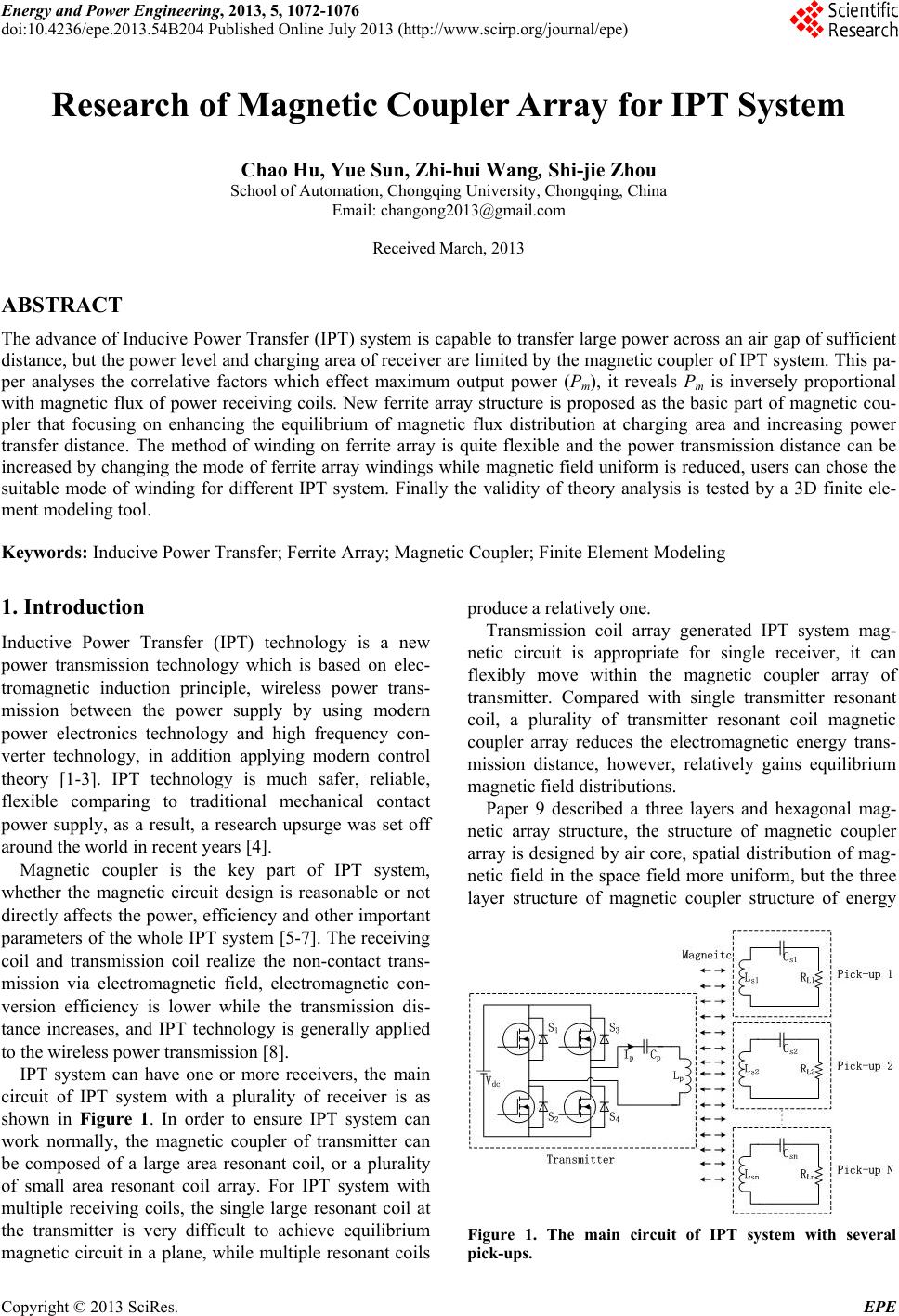
 Energy and Power Engineering, 2013, 5, 1072-1076 doi:10.4236/epe.2013.54B204 Published Online July 2013 (http://www.scirp.org/journal/epe) Research of Magnetic Co upler Array for IPT System Chao Hu, Yue Sun, Zhi-hui Wang, Shi-jie Zhou School of Automation, Chongqing University, Chongqing, China Email: changong2013@gmail.com Received March, 2013 ABSTRACT The advance of Inducive Power Transfer (IPT) system is capable to transfer large power across an air gap of sufficient distance, but the power level and charging area of receiver are limited by the magnetic coupler of IPT system. This pa- per analyses the correlative factors which effect maximum output power (Pm), it reveals Pm is inversely proportional with magnetic flux of power receiving coils. New ferrite array structure is proposed as the basic part of magnetic cou- pler that focusing on enhancing the equilibrium of magnetic flux distribution at charging area and increasing power transfer distance. The method of winding on ferrite array is quite flexible and the power transmission distance can be increased by changing the mode of ferrite array windings while magnetic field uniform is reduced, users can chose the suitable mode of winding for different IPT system. Finally the validity of theory analysis is tested by a 3D finite ele- ment modeling tool. Keywords: Inducive Power Transfer; Ferrite Array; Magnetic Coupler; Finite Element Modeling 1. Introduction Inductive Power Transfer (IPT) technology is a new power transmission technology which is based on elec- tromagnetic induction principle, wireless power trans- mission between the power supply by using modern power electronics technology and high frequency con- verter technology, in addition applying modern control theory [1-3]. IPT technology is much safer, reliable, flexible comparing to traditional mechanical contact power supply, as a result, a research upsurge was set off around the world in recent years [4]. Magnetic coupler is the key part of IPT system, whether the magnetic circuit design is reasonable or not directly affects the power, efficiency and other important parameters of the whole IPT system [5-7]. The receiving coil and transmission coil realize the non-contact trans- mission via electromagnetic field, electromagnetic con- version efficiency is lower while the transmission dis- tance increases, and IPT technology is generally applied to the wireless power transmission [8]. IPT system can have one or more receivers, the main circuit of IPT system with a plurality of receiver is as shown in Figure 1. In order to ensure IPT system can work normally, the magnetic coupler of transmitter can be composed of a large area resonant coil, or a plurality of small area resonant coil array. For IPT system with multiple receiving coils, the single large resonant coil at the transmitter is very difficult to achieve equilibrium magnetic circuit in a plane, while multiple resonant coils produce a relatively one. Transmission coil array generated IPT system mag- netic circuit is appropriate for single receiver, it can flexibly move within the magnetic coupler array of transmitter. Compared with single transmitter resonant coil, a plurality of transmitter resonant coil magnetic coupler array reduces the electromagnetic energy trans- mission distance, however, relatively gains equilibrium magnetic field distributions. Paper 9 described a three layers and hexagonal mag- netic array structure, the structure of magnetic coupler array is designed by air core, spatial distribution of mag- netic field in the space field more uniform, but the three layer structure of magnetic coupler structure of energy Figure 1. The main circuit of IPT system with several pick-ups. Copyright © 2013 SciRes. EPE 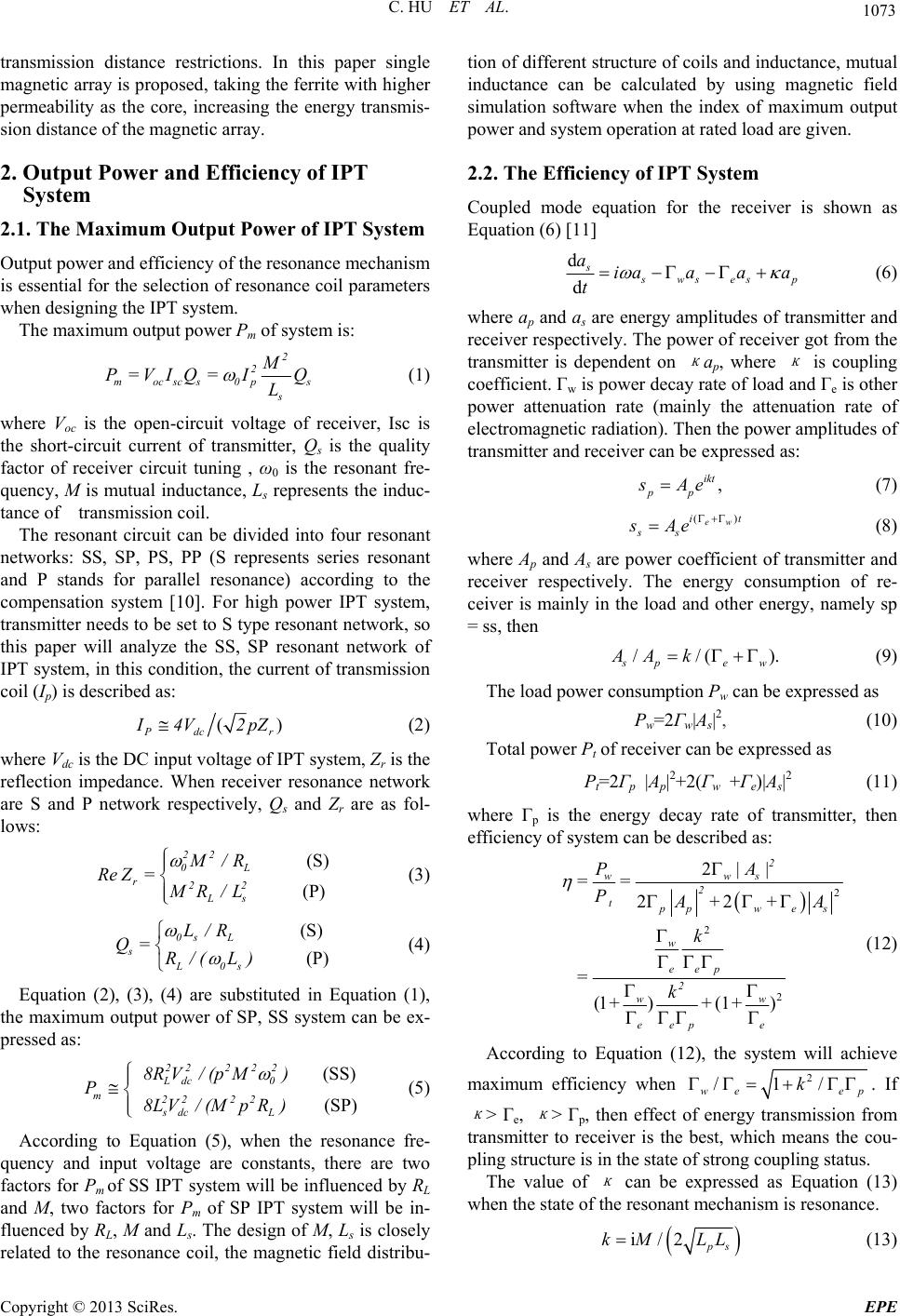 C. HU ET AL. 1073 transmission distance restrictions. In this paper single magnetic array is proposed, taking the ferrite with higher permeability as the core, increasing the energy transmis- sion distance of the magnetic array. 2. Output Power and Efficiency of IPT System 2.1. The Maximum Output Power of IPT System Output power and efficiency of the resonance mechanism is essential for the selection of resonance coil parameters when designing the IPT system. The maximum output power Pm of system is: 2 2 mocscs 0p s M P=VIQ= IQ L s (1) where Voc is the open-circuit voltage of receiver, Isc is the short-circuit current of transmitter, Qs is the quality factor of receiver circuit tuning , ω0 is the resonant fre- quency, M is mutual inductance, Ls represents the induc- tance of transmission coil. The resonant circuit can be divided into four resonant networks: SS, SP, PS, PP (S represents series resonant and P stands for parallel resonance) according to the compensation system [10]. For high power IPT system, transmitter needs to be set to S type resonant network, so this paper will analyze the SS, SP resonant network of IPT system, in this condition, the current of transmission coil (Ip) is described as: () dc r 4V2 pZ (2) where Vdc is the DC input voltage of IPT system, Zr is the reflection impedance. When receiver resonance network are S and P network respectively, Qs and Zr are as fol- lows: (S) (P) 22 0L r22 Ls M/R Re Z=MR/L (3) (S) (P) 0s L s L0s L/R Q= R/( L) (4) Equation (2), (3), (4) are substituted in Equation (1), the maximum output power of SP, SS system can be ex- pressed as: (SS) (SP) 222 22 Ldc 0 m22 22 sdc L 8RV/ (pM) P 8L V/(MpR) (5) According to Equation (5), when the resonance fre- quency and input voltage are constants, there are two factors for Pm of SS IPT system will be influenced by RL and M, two factors for Pm of SP IPT system will be in- fluenced by RL, M and Ls. The design of M, Ls is closely tion of different structure of coils and inductance, mutual inductance can be calculated by using magnetic field simulation software when the index of maximum output power and system operation at rated load are given. related to the resonance coil, the magnetic field distribu- 2.2. The Efficiency of IPT System er is shown as Coupled mode equation for the receiv Equation (6) [11] ds d ws esp ia aa a t a (6) where ap and as are energy amplitudes of transmitter and receiver respectively. The power of receiver got from the transmitter is dependent on κ ap, where κ is coupling coefficient. Γw is power decay rate of load and Γe is other power attenuation rate (mainly the attenuation rate of electromagnetic radiation). Then the power amplitudes of transmitter and receiver can be expressed as: , ikt pp Ae (7) (8) where Ap and As are power coefficie ). ( ew i ss sAe )t nt of transmitter and receiver respectively. The energy consumption of re- ceiver is mainly in the load and other energy, namely sp = ss, then //( spew AA k (9) The load power consumption Pw can be ) Total power Pt of re (11) where Γp is th expressed as Pw=2Γw|As|2, (10 ceiver can be expressed as Pt=2Γp |Ap|2+2(Γw +Γe)|As|2 e energy decay rate of transmitter, then efficiency of system can be described as: 2 2 2 22 wws P|A| 22 (1 )(1 ) 2 tppwe s w eep 2 ww eep e == P ++A k =k +++ (12) According to Equation (12), the system will achieve m aximum efficiency when 2 /1/ we ep k. If κ > Γe, κ > Γp, then effect orom f energy transmission f 3) w transmitter to receiver is the best, which means the cou- pling structure is in the state of strong coupling status. The value of κ can be expressed as Equation (1 hen the state of the resonant mechanism is resonance. i/2 s) kM LL (13 Copyright © 2013 SciRes. EPE 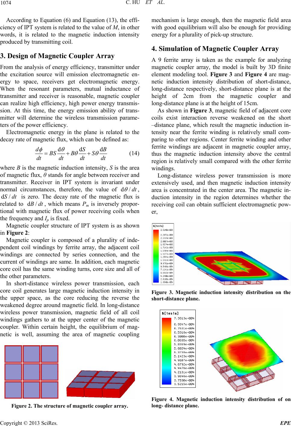 C. HU ET AL. 1074 According to Equation (6) and Eq ciency of IPT system is related to the w upler Array ter under netic en- hich can be defined as: uation (13), the effi- value of M, in other ords, it is related to the magnetic induction intensity produced by transmitting coil. 3. Design of Magnetic Co From the analysis of energy efficiency, transmit the excitation source will emission electromag ergy to space, receivers get electromagnetic energy. When the resonant parameters, mutual inductance of transmitter and receiver is reasonable, magnetic coupler can realize high efficiency, high power energy transmis- sion. At this time, the energy emission ability of trans- mitter will determine the wireless transmission parame- ters of the power efficiency. Electromagnetic energy in the plane is related to the decay rate of magnetic flux, w ddddSB BS BS dtdtdt dt (14) where B is the magnetic induction intensity of magnetic flux, θ stands for angle between receiver and , S is the area transmitter. Receiver in IPT system is invariant under normal circumstances, therefore, the value of d/dt , d/Sdt is zero. The decay rate of the magnetic flux is related to d/Bdt, which means Pm is inversely - ith magnetic flux of power receiving coils when the frequenIp is fixed. Magnetic coupler structure of IPT system is as shown in Figure 2: propor tional w cy and windings by ferrite array, the adjacent coil w ge magnetic induction intensity in th Magnetic coupler is composed of a plurality of inde- pendent coil indings are connected by series connection, and the current of windings are same. In addition, each magnetic core coil has the same winding turns, core size and all of the other parameters. In short-distance wireless power transmission, each core coil generates lar e upper space, as the core reducing the reverse the weakened degree around magnetic field. In long-distance wireless power transmission, magnetic field of all coil windings gathers to at the upper center of the magnetic coupler. Within certain height, the equilibrium of mag- netic is well, assuming the area of magnetic coupling Figure 2. The structure of magnetic coupler array. mechanism is large enough, then the magnetic field area with good equilibrium will also be enough for providing energy for a plurality of pick-up structure. 4. Simulation of Magnetic Coupler Array A 9 ferrite array is taken as the example for analyzing magnetic coupler array, the model is built by 3D finite elem ag- . ore ort ent modeling tool. Figure 3 and Figure 4 are m netic induction intensity distribution of short-distance, long-distance respectively, short-distance plane is at the height of 2cm from the magnetic coupler and long-distance plane is at the height of 15cm As shown in Figure 3, magnetic field of adjacent c coils exist interaction reverse weakened on the sh –distance plane, which result the magnetic induction in- tensity near the ferrite winding is relatively small com- paring to other regions. Center ferrite winding and other ferrite windings are adjacent in magnetic coupler array, thus the magnetic induction intensity above the central region is relatively small compared with the other ferrite windings. Long-distance wireless power transmission is more extensively used, and then magnetic induction intensity area is concentrated in the center area. The magnetic in- duction intensity in the region determines whether the receiving coil can obtain sufficient electromagnetic pow- er, Figure 3. Magnetic induction intensity distribution on the short-distance plane. Figure 4. Magnetic induction intensity distribution of on long- distance plane. Copyright © 2013 SciRes. EPE 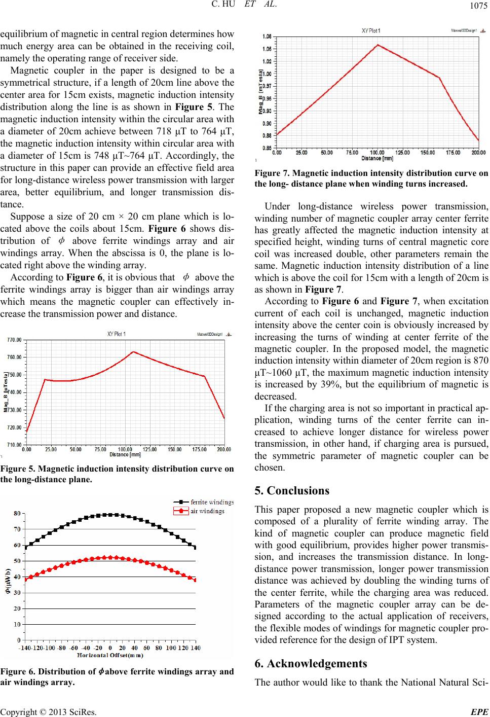 C. HU ET AL. 1075 equilibrium of magnetic in central region determines how much energy area can be obtained in the receiving coil, namely the operating range of receiver side. Magnetic coupler in the paper is designed to be a symmetrical structure, if a length of 20cm line above the center area for 15cm exists, magnetic induction intensity distribution along the line is as shown in Figure 5. The magnetic induction intensity within the circular area with a diameter of 20cm achieve between 718 μT to 764 μT, the magnetic induction intensity within circular area with a diameter of 15cm is 748 μT~764 μT. Accordingly, the structure in this paper can provide an effective field a ium, and longer transmission dis- shows dis- tri rea for long-distance wireless power transmission with larger area, better equilibr tance. Suppose a size of 20 cm × 20 cm plane which is lo- cated above the coils about 15cm. Figure 6 bution of φ above ferrite windings array and air windings array. When the abscissa is 0, the plane is lo- cated right above the winding array. According to Figure 6, it is obvious that φ above the ferrite windings array is bigger than air windings array which means the magnetic coupler can effectively in- crease the transmission power and distance. Figure 5. Magnetic induction intensity distribution curve on the long-distance plane. Figure 7. Magnetic induction intensity distribution curve on the long- distance plane when winding turns increased. magnetic coupler array center ferrite has greatly affected the magnetic induction intensity at specified height, winding turns of central magnetic core coil was increased double, other parameters remain the same. Magnetic induction intensity distribution of a line which is above the coil for 15cm with a length of 20cm is as shown in Figure 7. According to Figure 6 and Figure 7, when excitation current of each coil is unchanged, magnetic induction intensity above the center coin is obviously increased by increasing the turns of winding at center ferrite of the magnetic coupler. In the proposed model, the magnetic de owledgements The author would like to thank the National Natural Sci- Under long-distance wireless power transmission, winding number of induction intensity within diameter of 20cm region is 870 μT~1060 μT, the maximum magnetic induction intensity increased by 39%, but the equilibrium of magnetic is is creased. If the charging area is not so important in practical ap- plication, winding turns of the center ferrite can in- creased to achieve longer distance for wireless power transmission, in other hand, if charging area is pursued, the symmetric parameter of magnetic coupler can be chosen. 5. Conclusions This paper proposed a new magnetic coupler which is composed of a plurality of ferrite winding array. The kind of magnetic coupler can produce magnetic field with good equilibrium, provides higher power transmis- sion, and increases the transmission distance. In long- distance power transmission, longer power transmission distance was achieved by doubling the winding turns of the center ferrite, while the charging area was reduced. Parameters of the magnetic coupler array can be de- signed according to the actual application of receivers, the flexible modes of windings for magnetic coupler pro- vided reference for the design of IPT system. 6. Ackn Figure 6. Distribution of φ above ferrite windings array and air windings array. Copyright © 2013 SciRes. EPE  C. HU ET AL. Copyright © 2013 SciRes. EPE 1076 China (Grant No. 51277192) f ed Magnetic 17, No.5834, 2007, pp .1143254 ence Foundation ofor fi- nancial support. REFERENCES [1] Mickel Budhia, G. A. Covic, J. T. Boys, “Design and Optimisation of Magnetic Structures for Lumped Induc- tive power Transfer Systems,” IEEE Energy Conversion Congress and Exposition, 2009, pp. 2081-2088. [2] Aristeidis Karalis, J. D. Joannopoulos, Marin Soljacic, “Efficient Wireless Non-radiative Mid-range Energy Transfer,” Annals of Phisics, 2007, pp. 34-48. [3] André Kurs, Aristeidis Karalis, Robert Moffatt, et al., “Wireless Power Transfer via Strongly Coupl Resonances,” Science, Vol. 3 83-86. . doi:10.1126/science onics, Vol. 24, No.2, 2009, pp. 416-425. doi:10.1109/TPEL.2008.2007642 [4] C. S. Tang, Y. Sun, Y. G. Su, “Determining Multiple Steady-state ZCS Operating Points of a Switch-mode Contactless Power Transfer System,” IEEE Transactions Power Electr [5] Mickel BudhiaNew IPT Magnetic Coupler for Eg Systems,” IEEE ac- ciety, Vol. 23, No. 7, and , G. Covic, J. Boys, “A lectric Vehicle Chargin Industrial Electronics Society, 2010, pp.2487-2492. [6] C. S. Tang, X. Dai, Z. H. Wang, Y. Sun and A. P. Hu, “Frequency Bifurcation Phenomenon Study of a Soft Switched Push-pull Contactless Power Transfer System,” in Proc. IEEE Conf. Ind. Electron, 2011, pp. 1981-1986. [7] Y. G. Su, Z. H. Wang, Y. Sun, et al., “Research of Phase Shift Control System Modeling Based on IPT,” Trans tions of China Electrotechnical So 2008, pp. 92-97. [8] W. X. Zhong, C. K. Lee and S. Y. Hui, “Wireless Power Domino-resonator Systems with Noncoaxial Axes Circular Structures,” IEEE Transactions Power Electron- ics, Vol. 27, No. 11, 2012, pp. 4750-4762. doi:10.1109/TPEL.2011.2174655 [9] S. Y. R. Hui, W. C. H. Wing, “A New Generation of Universal Contactless Battery Charging Platform for Portable Consumer Electronic Equipment,” IEEE Trans- actions on Power Electronics, Vol. 20, No. 3, 2005, pp. 620—627. doi:10.1109/TPEL.2005.846550 [10] J. Huh, S. W. Lee, W. Y. Lee, G. H. Cho and C. T. Rim, “Narrow-width Inductive Power Transfer System for Online Electrical Vehicles,” IEEE Transa Electronics, Vol. 26, No. 12, 2011, ctions Power pp. 3666-3679. doi:10.1109/TPEL.2011.2160972 [11] H. A. Haus, “Waves and Fields in Optoelectronics,” Prentice-Hall, New Jersey, 1984.
|