Paper Menu >>
Journal Menu >>
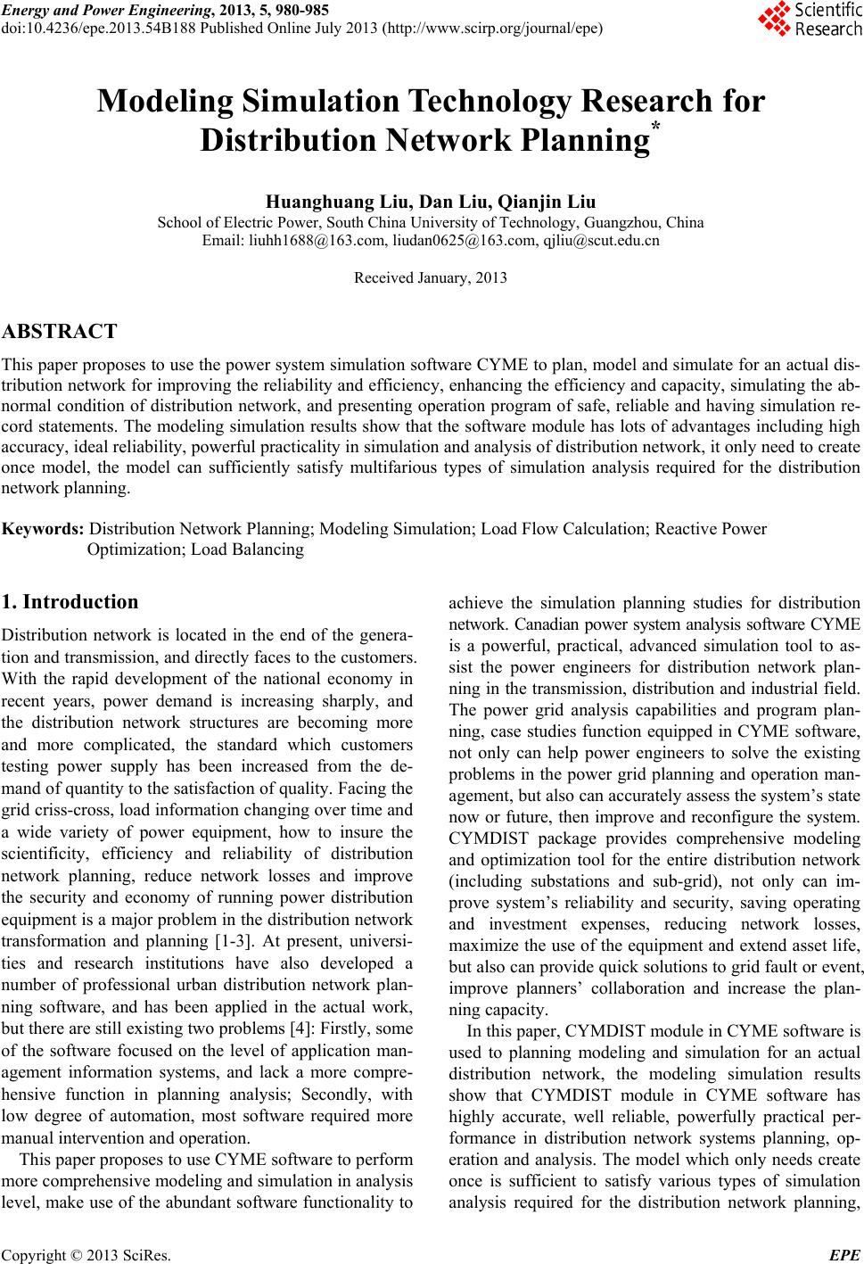 Energy and Power Engineering, 2013, 5, 980-985 doi:10.4236/epe.2013.54B188 Published Online July 2013 (http://www.scirp.org/journal/epe) Modeling Simulation Technology Research for Distribution Network Planning* Huanghuang Liu, Dan Liu, Qianjin Liu School of Electric Power, South China University of Technology, Guangzhou, China Email: liuhh1688@163.com, liudan0625@163.com, qjliu@scut.edu.cn Received January, 2013 ABSTRACT This paper proposes to use the power system simulation software CYME to plan, model and simulate for an actual dis- tribution network for improvin g the reliability and efficiency, enhancing the efficiency and capacity, simulating the ab- normal condition of distribution network, and presenting operation program of safe, reliable and having simulation re- cord statements. The modeling simulation results show that the software module has lots of advantages including high accuracy, ideal reliability, powerful practicality in simulation and analysis of distribution network, it only need to create once model, the model can sufficiently satisfy multifarious types of simulation analysis required for the distribution network pl anning. Keywords: Distribution Network Planning; Modeling Simulation; Load Flow Calculation; Reactive Power Optimization; Load Balancing 1. Introduction Distribution network is located in the end of the genera- tion and transmission, and directly faces to the customers. With the rapid development of the national economy in recent years, power demand is increasing sharply, and the distribution network structures are becoming more and more complicated, the standard which customers testing power supply has been increased from the de- mand of quantity to th e satisfaction of quality. Facing the grid criss-cross, load information ch anging over time and a wide variety of power equipment, how to insure the scientificity, efficiency and reliability of distribution network planning, reduce network losses and improve the security and economy of running power distribution equipment is a major problem in the distribution network transformation and planning [1-3]. At present, universi- ties and research institutions have also developed a number of professional urban distribution network plan- ning software, and has been applied in the actual work, but there are still existing two problems [4]: Firstly, some of the software focused on the level of application man- agement information systems, and lack a more compre- hensive function in planning analysis; Secondly, with low degree of automation, most software required more manual interv ention and operation. This paper proposes to use CYME software to perform more comprehensive modeling and simulation in analysis level, make use of the abundan t software functionality to achieve the simulation planning studies for distribution network. Canadian power system analysis software CYME is a powerful, practical, advanced simulation tool to as- sist the power engineers for distribution network plan- ning in the transmission, distribution and industrial field. The power grid analysis capabilities and program plan- ning, case studies function equipped in CYME software, not only can help power engineers to solve the existing problems in the power grid planning and operation man- agement, but also can accurately assess the system’s state now or future, then improve and reconfigure the system. CYMDIST package provides comprehensive modeling and optimization tool for the entire distribution network (including substations and sub-grid), not only can im- prove system’s reliability and security, saving operating and investment expenses, reducing network losses, maximize the use of the equipment and extend asset life, but also can provide quick solutions to grid fault or event, improve planners’ collaboration and increase the plan- ning capacity. In this paper, CYMDIST module in CYME software is used to planning modeling and simulation for an actual distribution network, the modeling simulation results show that CYMDIST module in CYME software has highly accurate, well reliable, powerfully practical per- formance in distribution network systems planning, op- eration and analysis. The model which only needs create once is sufficient to satisfy various types of simulation analysis required for the distribution network planning, Copyright © 2013 SciRes. EPE 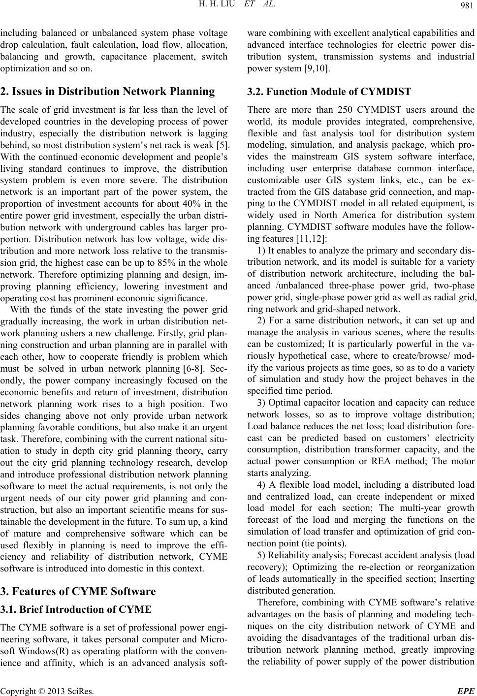 H. H. LIU ET AL. 981 including balanced or unbalanced system phase voltage drop calculation, fault calculation, load flow, allocation, balancing and growth, capacitance placement, switch optimization and so on. 2. Issues in Distribution Network Planning The scale of grid investment is far less than the level of developed countries in the developing process of power industry, especially the distribution network is lagging behind, so most distribution system’s net rack is weak [5]. With the continued economic development and people’s living standard continues to improve, the distribution system problem is even more severe. The distribution network is an important part of the power system, the proportion of investment accounts for about 40% in the entire power grid investment, especially the urban distri- bution network with underground cables has larger pro- portion. Distribution network has low voltage, wide dis- tribution and more network loss relative to the transmis- sion grid, the highe st case can be up to 85% in the whole network. Therefore optimizing planning and design, im- proving planning efficiency, lowering investment and operating cost has prominent economic significance. With the funds of the state investing the power grid gradually increasing, the work in urban distribution net- work planning ushers a new challenge. Firstly, grid plan- ning constru ction and urban planning are in parallel w ith each other, how to cooperate friendly is problem which must be solved in urban network planning [6-8]. Sec- ondly, the power company increasingly focused on the economic benefits and return of investment, distribution network planning work rises to a high position. Two sides changing above not only provide urban network planning favorable cond itions, but also make it an urgent task. Therefore, combining with the current national situ- ation to study in depth city grid planning theory, carry out the city grid planning technology research, develop and introduce professional distribution network planning software to meet the actual requirements, is not only the urgent needs of our city power grid planning and con- struction, but also an important scientific means for sus- tainable the development in the future. To sum up, a kind of mature and comprehensive software which can be used flexibly in planning is need to improve the effi- ciency and reliability of distribution network, CYME software is introduced into domestic in this context. 3. Features of CYME Software 3.1. Brief Introduction of CYME The CYME software is a set of professional power engi- neering software, it takes personal computer and Micro- soft Windows(R) as operating platform with the conven- ience and affinity, which is an advanced analysis soft- ware combining with excellent analytical cap abilities and advanced interface technologies for electric power dis- tribution system, transmission systems and industrial power system [9,10]. 3.2. Function Module of CYMDIST There are more than 250 CYMDIST users around the world, its module provides integrated, comprehensive, flexible and fast analysis tool for distribution system modeling, simulation, and analysis package, which pro- vides the mainstream GIS system software interface, including user enterprise database common interface, customizable user GIS system links, etc., can be ex- tracted from the GIS database grid connection, and map- ping to the CYMDIST model in all related equipment, is widely used in North America for distribution system planning. CYMDIST software modules have the follow- ing features [11,12]: 1) It enables to analyze the primary and secondary dis- tribution network, and its model is suitable for a variety of distribution network architecture, including the bal- anced /unbalanced three-phase power grid, two-phase power grid, single-phase power grid as well as radial grid, ring network and grid-shaped network. 2) For a same distribution network, it can set up and manage the analysis in various scenes, where the results can be customized; It is particularly powerful in the va- riously hypothetical case, where to create/browse/ mod- ify the various projects as time goes, so as to do a variety of simulation and study how the project behaves in the specified time period. 3) Optimal capacitor location and capacity can reduce network losses, so as to improve voltage distribution; Load balance reduces the net loss; load distribution fore- cast can be predicted based on customers’ electricity consumption, distribution transformer capacity, and the actual power consumption or REA method; The motor starts analyzing. 4) A flexible load model, including a distributed load and centralized load, can create independent or mixed load model for each section; The multi-year growth forecast of the load and merging the functions on the simulation of load transfer and optimization of grid con- nection point (tie points). 5) Reliability analysis; Forecast accident analysis (load recovery); Optimizing the re-election or reorganization of leads automatically in the specified section; Inserting distributed generation . Therefore, combining with CYME software’s relative advantages on the basis of planning and modeling tech- niques on the city distribution network of CYME and avoiding the disadvantages of the traditional urban dis- tribution network planning method, greatly improving the reliability of power supply of the power distribution Copyright © 2013 SciRes. EPE 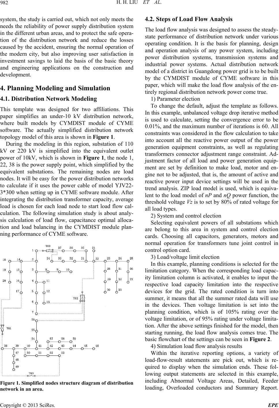 H. H. LIU ET AL. 982 system, the study is carried out, which not only meets the needs the reliability of power supply distribution system in the different urban areas, and to protect the safe opera- tion of the distribution network and reduce the losses caused by the accident, ensuring the normal operation of the modern city, but also improving user satisfaction in investment savings to laid the basis of the basic theory and engineering applications on the construction and development. 4. Planning Modeling and Simulation 4.1. Distribution Network Modeling This template was designed for two affiliations. This paper simplifies an under-10 kV distribution network, where built models by CYMDIST module of CYME software. The actually simplified distribution network topology model of this area is shown in Figure 1. During the modeling in this region, substation of 110 kV or 220 kV is simplified into the equivalent outlet power of 10kV, which is shown in Figure 1, the node 1, 22, 38 is the power supply po int, which simplified by the equivalent substations. The remaining nodes are load nodes. It will be easy for the power distribution network s to calculate if it uses the power cable of model YJV22- 3*300 when setting up in CYME software module. After integrating the distribution transformer capacity, average load is chosen for each load node to start load flow cal- culation. The following simulation study is about analy- sis calculation of load flow, capacitance optimal alloca- tion and load balancing in the CYMDIST module plan- ning perfo rmance of CYM E sof tware. Figure 1. Simplified nodes structure diagram of distribution network in an area. 4.2. Steps of Load Flow Analysis The load flow analysis was designed to assess the steady- state performance of distribution network under various operating condition. It is the basis for planning, design and operation analysis of any power system, including power distribution systems, transmission systems and industrial power systems. Actual distribution network model of a district in Guangdong power grid is to be built by the CYMDIST module of CYME software in this paper, which will make the load flow analysis of the en- tirely regional distribution network power come tru e . 1) Parameter election To change the default, adjust the template as follows. In this example, unbalanced voltage drop iterative method is used to calculate, setting the convergence error to be 0.01%, and the maximum number of iterations is 60. All constraints was considered in th e flow calculation to take into account all the reactive power output of the power generation equipment constraints, as well as regulating transformers connector adjustment range constraint. Ad- justment factor of all load and power generation equip- ment are set by definition to make load, motor and en- gine not to be adjusted, that is, the amount of active and reactive power input device settings will be used in the trend analysis. ZIP load model is used, which is equiva- lent to the load model of nP and nQ power function, the threshold voltage Vz is to set by 80% of rated voltage for all load types. 2) System and control election Selecting equivalent powers of all substations which are belong to this area in system and control election cards. Choosing all capacitors, generators, motors and normal operation for transformers tune joint control in control option card. 3) Load/voltage limit electio n In this example, planning cond itions is selected for the limitation category. When the corresponding load capac- ity limitation column is activated, it enables to input the respective load capacity limitation into the respective devices for the grid. The rated condition is turn into summer, it means that all the summer rated data will use in the devices. Then voltage limitation is set into the planning condition, which is of 105% rating over the voltage limitatio n, or of 95% rating under voltage limita- tion. After the above settings finish ed for the model, then starting running, the load flow analysis comes true. The basic flowchart of the settings can be seen in Figure 2. 4) Simulation load flow analysis results Within the iterative reporting options, a variety of load-flow-result statements are pick out, which is re- quired to display when the simulation ends. These fol- lowing output statements are selected in this example, including Abnormal Voltage Areas, Detailed, Feeder loading, Overloaded conductors and Summary Report. Copyright © 2013 SciRes. EPE  H. H. LIU ET AL. 983 The electricity price is 0.9635 yuan/kWh according to the commercially electric degree from 1 to 10 kV, which can be converted to 0.1547 $/kWh in CYME software units. Because of the space limitations, this paper only lists 2 load flow consolidated statements as shown in Tables 1-2. Figure 2. Flow chart of load flow analysis. Table 1. Total summary rep ort of load flow. Total Summary kW kVAR kVA PF (%) Sources (Swing) 34182.45 20582.03 39900.63 85.67 Total generation 34182.45 20582.03 39900.63 85.67 Load read (Non-adjusted) 34182.5 21184.41 40214.7 85 Load used (Adjust) 34182.32 21184.27 40214.48 85 Total loads 34182.32 21184.27 40214.48 85 Cable capacitance 0 602.44 602.44 0 Table 2. Economic loss report. Annual Cost of System Losses kW MW-h/year k$/year Cable losses 0.13 1.1387 0.1762 Total losses 0.13 1.1387 0.1762 4.3. Reactive Power Optimization Allocation Reactive power optimization can install capacitor bank in the optimum position of feeders to obtain the optimal load flow distribution with the minimum active power loss or improvement of system voltage. For the lower Cable impedance, capacitive compensation test should not be done. As a result, with the line cable where the load nodes 34, 35, 36, 37 lyin g replaced by the overhead line of model JKLYJ-240, the line will appear low volt- age fault when running the load flow analysis. In order to solve the problem, it is necessary for capacitor layout to have an optimized analysis so as to improve voltage dis- tribution. Under-voltage limitin g value is set as the rating of 97.5 percent, the threshold voltage is 0.98 kV and tar- get voltage is 10 kV. When feeder voltage is less than threshold voltage value, the capacitor analysis program will be started; Minimum switched capacity is 1 kVAR/ phase, maximum is 200 kVAR/phase, and capacity in- crement is 1 kVAR/phase. Moreover, the capacitor bank is installed in one place only. The feeder load level set- ting is based on the display value under the load level election card. After running the analysis of the optimal capacitor placement, the results card will recommend the optimal installation site of the cap acitor bank in a tree list, that is, capacity of the capacitor bank, active power number of net loss, voltage increment and power factor correction etc. In addition, when the recommended capacitor bank installed, the problem of under-voltage on the feeder is solved after running the load flow analysis again. CYM- DIST analysis program automatically generates capacitor bank installation information as shown in Table 3, the voltage distribution of feeder different from the power supply point to the caudal section before and after the capacitance optimization placement, as shown in Figure 3. Comparing the two graphs in Figure 3, the three-phase voltage will decrease to the under-voltage limitation as the distance between the feeder and the power supply Table 3. Installation information of capacitor. Information kVAR total kW total % Fixed capacitance 192.0 Switched capacitor 99.0 Capacitance size /phase 97.0 Loss reduction 0.7 Ideal power factor 90.0 Power factor correcti on 86.6 Voltage increment 2.36 Copyright © 2013 SciRes. EPE 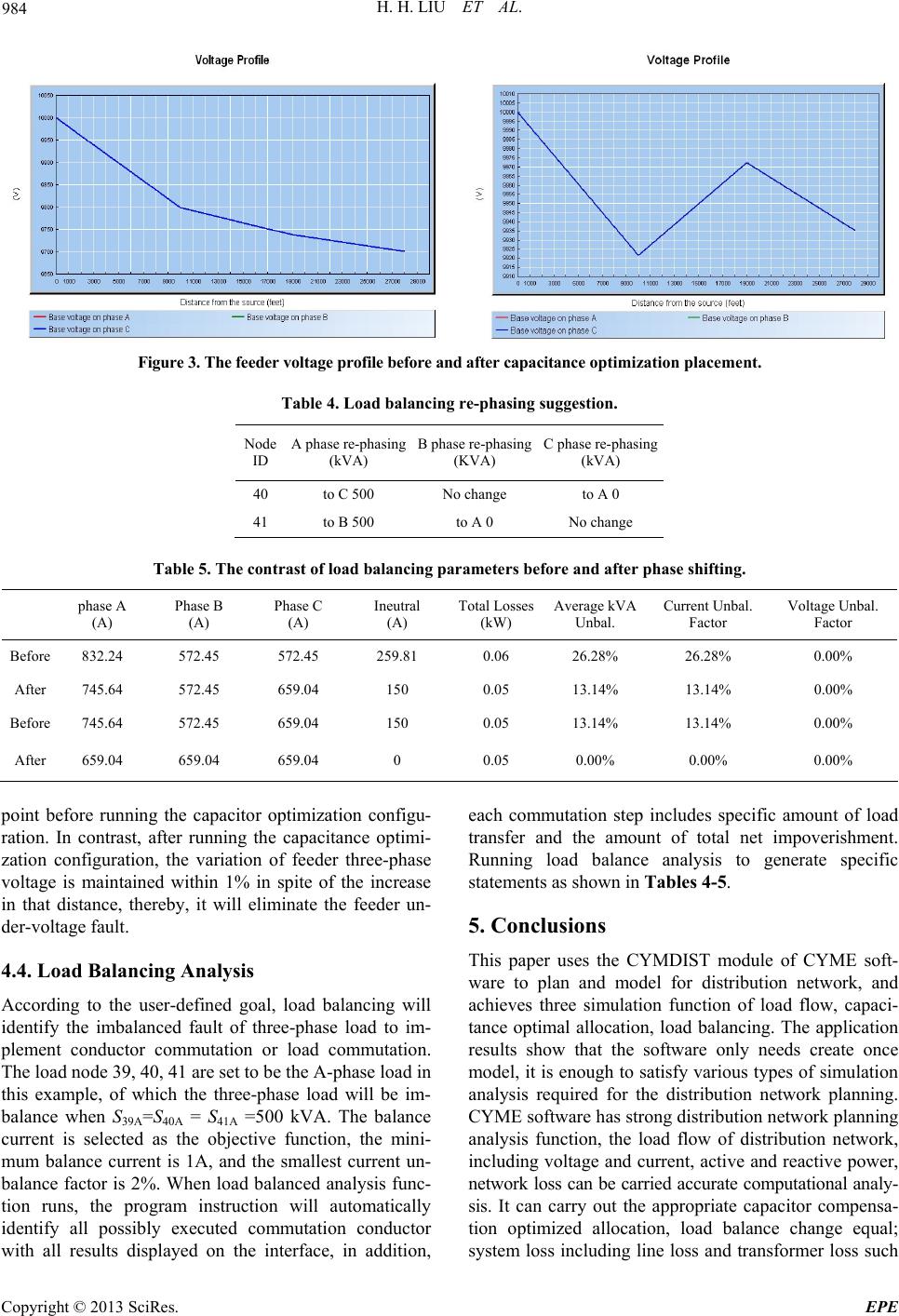 H. H. LIU ET AL. Copyright © 2013 SciRes. EPE 984 Figure 3. The feeder voltage profile before and after capacitance optimization placement. Table 4. Load balancing re-phasing suggestion. Node ID A phase re-phasing (kVA) B phase re-phasing (KVA) C phase re-phasing (kVA) 40 to C 500 No change to A 0 41 to B 500 to A 0 No change Table 5. The contrast of load balancing parameters before and after phase sh ifting. phase A (A) Phase B (A) Phase C (A) Ineutral (A) Total Losses (kW) Average kVA Unbal. Current Unbal . Factor Voltage Unbal. Factor Before 832.24 572.45 572.45 259.81 0.06 26.28% 26.28% 0.00% After 745.64 572.45 659.04 150 0.05 13.14% 13.14% 0.00% Before 745.64 572.45 659.04 150 0.05 13.14% 13.14% 0.00% After 659.04 659.04 659.04 0 0.05 0.00% 0.00% 0.00% point before running the capacitor optimization configu- ration. In contrast, after running the capacitance optimi- zation configuration, the variation of feeder three-phase voltage is maintained within 1% in spite of the increase in that distance, thereby, it will eliminate the feeder un- der-voltage fault. 4.4. Load Balancing Analysis According to the user-defined goal, load balancing will identify the imbalanced fault of three-phase load to im- plement conductor commutation or load commutation. The load node 39, 40, 41 are set to be the A-phase load in this example, of which the three-phase load will be im- balance when S39A=S40A = S41A =500 kVA. The balance current is selected as the objective function, the mini- mum balance current is 1A, and the smallest current un- balance factor is 2%. When load balanced analysis func- tion runs, the program instruction will automatically identify all possibly executed commutation conductor with all results displayed on the interface, in addition, each commutation step includes specific amount of load transfer and the amount of total net impoverishment. Running load balance analysis to generate specific statements as shown in Tables 4-5. 5. Conclusions This paper uses the CYMDIST module of CYME soft- ware to plan and model for distribution network, and achieves three simulation function of load flow, capaci- tance optimal allocation, load balancing. The application results show that the software only needs create once model, it is enough to satisfy various types of simulation analysis required for the distribution network planning. CYME software has strong distribution network planning analysis function, the load flow of distribution network, including voltage and current, active and reactive power, network loss can be carried accurate computational analy- sis. It can carry out the appropriate capacitor compensa- tion optimized allocation, load balance change equal; system loss including line loss and transformer loss such  H. H. LIU ET AL. 985 as the annual economic losses can be carried quantify the estimates. Summary, CYME software brings the facili- ties for distribution network planning, improves the reli- ability and enhance the efficiency and capacity of distri- bution network planning, laying a solid foundation for the future distribution network to be intelligent and effi- cient. REFERENCES [1] L. J. Liu, R. Hu, Y. Fu, et al., “Comprehensive Evalua- tion of Resource Economy Based Distribution Network Planning Scheme,” Power System Technology, Vol. 32, No. 16, 2008, pp. 66-70. [2] T. Kong, H. Z. Chen and T. Y. Xu, “Urban Me- dium-voltage Distribution Network Planning Based on ComGIS Network Analysis and Multi-objective Genetic Algorithm,” Proceedings of the CSEE, Vol. 19, No. 28, 2008, pp. 49-55. [3] T. Kong, H. Z. Chen, G. Li, et al., “ Review of Power Distribution Network Planning,” Power System Technol- ogy, Vol. 19, No. 33, 2009, pp. 92-99. [4] Q. H. Liu, J. H. Yang and P. Yang, “Distribution Network Planning and Reconstruction Software Based on GIS Component,” Power System Protection and Control, Vol. 38, No. 4, 2010, pp. 106-109. [5] W. H. Yang, Q. R. Gu and X. Z. Hang, “Attention on the Distribution Power Network Planning During New Pe- riod,” Power System Technology, Vol. 30, No. S2, 2006, pp. 588-590. [6] D. T. C. Wang, L. F. Ochoa and G. P. Harrison, “Modi- fied GA and Data Envelopment Analysis for Multistage Distribution Network Expansion Planning Under Uncer- tainty,” IEEE Transactions on Power Systems, Vol. 26, No. 2, 2011, pp. 897-904. doi:/10.1109/TPWRS.2010.2057457 [7] C. S. Wang, S. Y. Wang, “The Intelligent Planning of Urban Mid-voltage Distribution Network Based on Spa- tial GIS Part one Automatic Routing of Radial Network,” Automation of Electric Power Systems, Vol. 28, No. 5, 2004, pp. 45-50. [8] J. A. Peralta, F. de Leon and J. Mahseredjian, “Unbal- anced Multiphase Load-Flow Using a Positive-Sequence Load-Flow Program,” IEEE Transactions on Power Sys- tems, Vol. 23, No. 2, 2008, pp. 469-476. doi:10.1109/TPWRS.2008.920184 [9] Cooper Industry and Power System Division, “CYME Power Engineering Analysis Simulation Software and Solutions,” Cooper Electric (Shanghai) co., LTD, 2011. [10] M. A. Salam, Koh Ming Jen and M. A. Khan, “Measure- ment and Simulation of Grounding Resistance with Two and Four Mesh Grids,” Proceedings of IEEE Conference on Power Electronics and Drive Systems (PEDS), Singa- pore, 2011. [11] CYMDIST Version 5.02 Reference Manual, Canada: CYME International T&D Inc., 2010. [12] H. K. Karegar and M. Arabi, “New Wind Turbine Grounding System to Reduce Step & Touch Voltage,” Proceedings of IEEE Conference on Power and Energy (PECon), Kuala Lumpur, Malaysia, 2010. Copyright © 2013 SciRes. EPE |