Paper Menu >>
Journal Menu >>
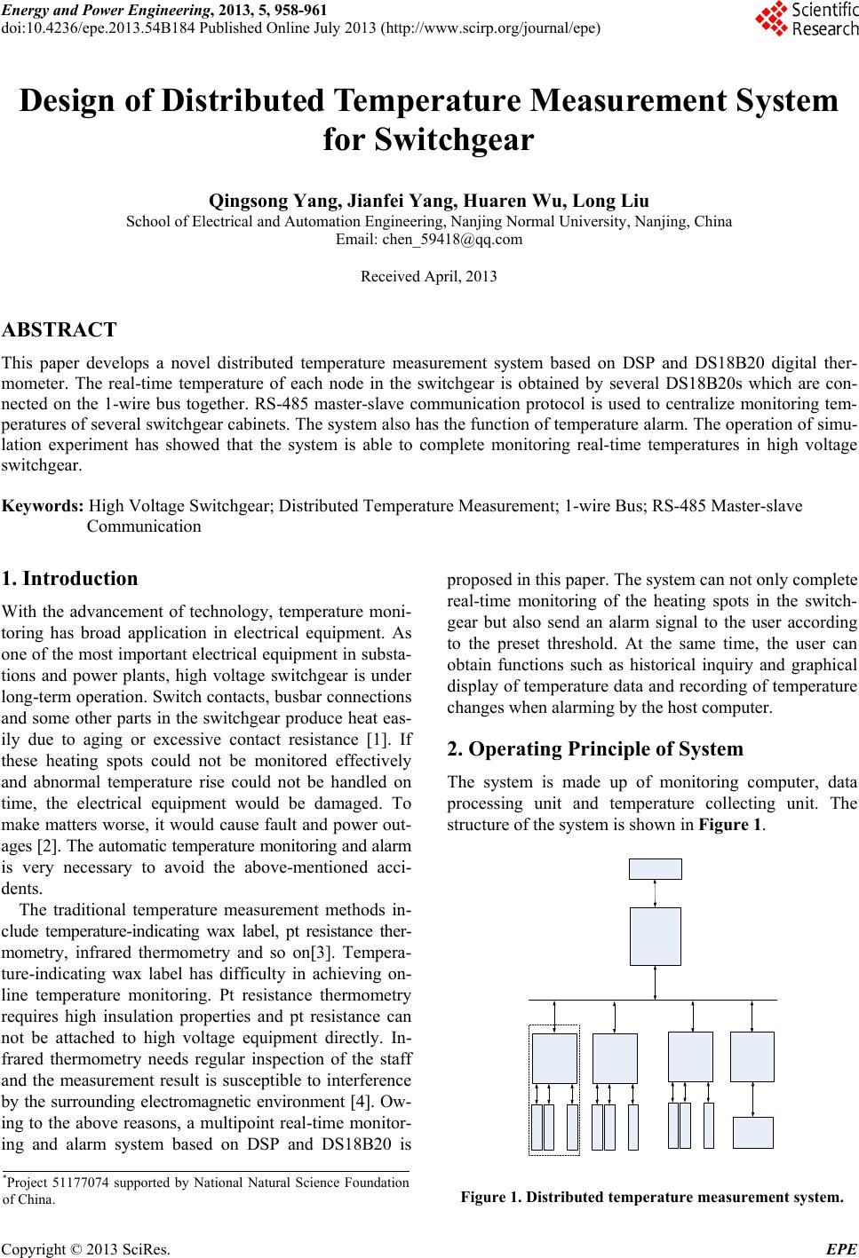 Energy and Power Engineering, 2013, 5, 958-961 doi:10.4236/epe.2013.54B184 Published Online July 2013 (http://www.scirp.org/journal/epe) Design of Distributed Temperature Measurement System for Switchgear Qingsong Yang, Jianfei Yang, Huaren Wu, Long Liu School of Electrical and Automation Engineering, Nanjing Normal University, Nanjing, China Email: chen_59418@qq.com Received April, 2013 ABSTRACT This paper develops a novel distributed temperature measurement system based on DSP and DS18B20 digital ther- mometer. The real-time temperature of each node in the switchgear is obtained by several DS18B20s which are con- nected on the 1-wire bus together. RS-485 master-slave communication protocol is used to centralize monitoring tem- peratures of several switchgear cabinets. The system also has the function of temperature alarm. The operation of simu- lation experiment has showed that the system is able to complete monitoring real-time temperatures in high voltage switchgear. Keywords: High Voltage Switchgear; Distributed Temperature Measurement; 1-wire Bus; RS-485 Master-slave Communication 1. Introduction With the advancement of technology, temperature moni- toring has broad application in electrical equipment. As one of the most important electrical equipment in substa- tions and power plants, high voltage switchgear is under long-term operation. Switch contacts, busbar connections and some other parts in the switchgear produce heat eas- ily due to aging or excessive contact resistance [1]. If these heating spots could not be monitored effectively and abnormal temperature rise could not be handled on time, the electrical equipment would be damaged. To make matters worse, it would cause fault and power out- ages [2]. The automatic temperature monitoring and alarm is very necessary to avoid the above-mentioned acci- dents. The traditional temperature measurement methods in- clude temperature-indicating wax label, pt resistance ther- mometry, infrared thermometry and so on[3]. Tempera- ture-indicating wax label has difficulty in achieving on- line temperature monitoring. Pt resistance thermometry requires high insulation properties and pt resistance can not be attached to high voltage equipment directly. In- frared thermometry needs regular inspection of the staff and the measurement result is susceptible to interference by the surrounding electromagnetic environment [4]. Ow- ing to the above reasons, a multipoint real-time monitor- ing and alarm system based on DSP and DS18B20 is proposed in this paper. The system can not only complete real-time monitoring of the heating spots in the switch- gear but also send an alarm signal to the user according to the preset threshold. At the same time, the user can obtain functions such as historical inquiry and graphical display of temperature data and recording of temperature changes when alarming by the host computer. 2. Operating Principle of System The system is made up of monitoring computer, data processing unit and temperature collecting unit. The structure of the system is shown in Figure 1. *Project 51177074 supported by National Natural Science Foundation of China. Figure 1. Distributed temperature measurement system. Copyright © 2013 SciRes. EPE 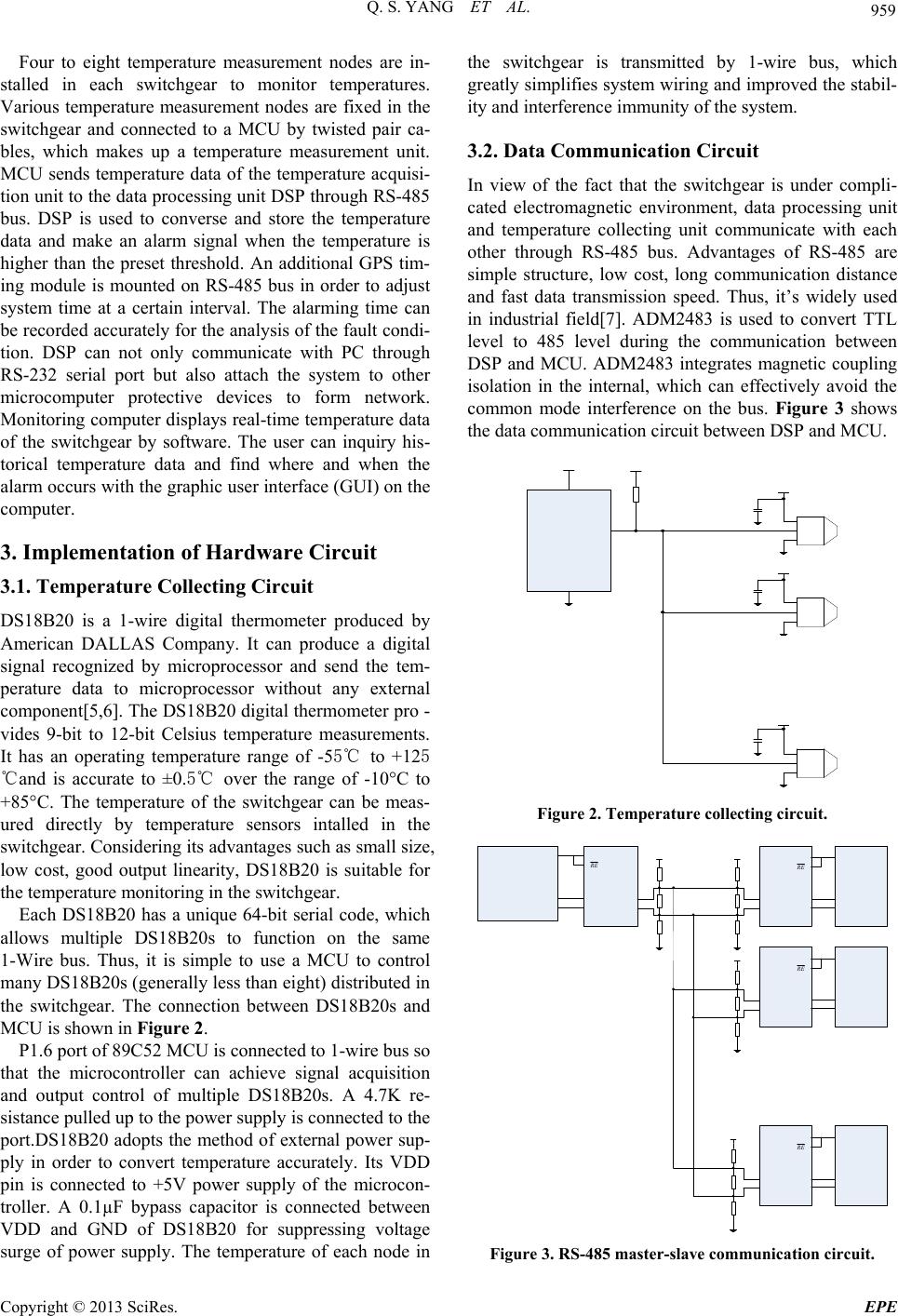 Q. S. YANG ET AL. 959 Four to eight temperature measurement nodes are in- stalled in each switchgear to monitor temperatures. Various temperature measurement nodes are fixed in the switchgear and connected to a MCU by twisted pair ca- bles, which makes up a temperature measurement unit. MCU sends temperature data of the temperature acquisi- tion unit to the data processing unit DSP through RS-485 bus. DSP is used to converse and store the temperature data and make an alarm signal when the temperature is higher than the preset threshold. An additional GPS tim- ing module is mounted on RS-485 bus in order to adjust system time at a certain interval. The alarming time can be recorded accurately for the analysis of the fault condi- tion. DSP can not only communicate with PC through RS-232 serial port but also attach the system to other microcomputer protective devices to form network. Monitoring computer displays real-time temperature data of the switchgear by software. The user can inquiry his- torical temperature data and find where and when the alarm occurs with the graphic user interface (GUI) on the computer. 3. Implementation of Hardware Circuit 3.1. Temperature Collecting Circuit DS18B20 is a 1-wire digital thermometer produced by American DALLAS Company. It can produce a digital signal recognized by microprocessor and send the tem- perature data to microprocessor without any external component[5,6]. The DS18B20 digital thermometer pro - vides 9-bit to 12-bit Celsius temperature measurements. It has an operating temperature range of -55℃ to +125 ℃and is accurate to ±0.5℃ over the range of -10°C to +85°C. The temperature of the switchgear can be meas- ured directly by temperature sensors intalled in the switchgear. Considering its advantages such as small size, low cost, good output linearity, DS18B20 is suitable for the temperature monitoring in the switchgear. Each DS18B20 has a unique 64-bit serial code, which allows multiple DS18B20s to function on the same 1-Wire bus. Thus, it is simple to use a MCU to control many DS18B20s (generally less than eight) distributed in the switchgear. The connection between DS18B20s and MCU is shown in Figure 2. P1.6 port of 89C52 MCU is connected to 1-wire bus so that the microcontroller can achieve signal acquisition and output control of multiple DS18B20s. A 4.7K re- sistance pulled up to the power supply is connected to the port.DS18B20 adopts the method of external power sup- ply in order to convert temperature accurately. Its VDD pin is connected to +5V power supply of the microcon- troller. A 0.1µF bypass capacitor is connected between VDD and GND of DS18B20 for suppressing voltage surge of power supply. The temperature of each node in the switchgear is transmitted by 1-wire bus, which greatly simplifies system wiring and improved the stabil- ity and interference immunity of the system. 3.2. Data Communication Circuit In view of the fact that the switchgear is under compli- cated electromagnetic environment, data processing unit and temperature collecting unit communicate with each other through RS-485 bus. Advantages of RS-485 are simple structure, low cost, long communication distance and fast data transmission speed. Thus, it’s widely used in industrial field[7]. ADM2483 is used to convert TTL level to 485 level during the communication between DSP and MCU. ADM2483 integrates magnetic coupling isolation in the internal, which can effectively avoid the common mode interference on the bus. Figure 3 shows the data communication circuit between DSP and MCU. Figure 2. Temperature collecting circuit. R E R E R E R E Figure 3. RS-485 master-slave communication circui t. Copyright © 2013 SciRes. EPE 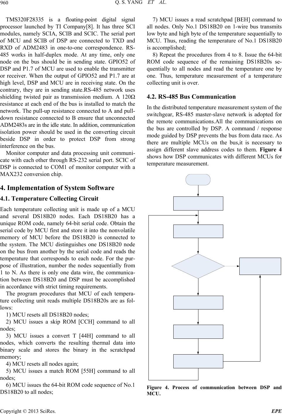 Q. S. YANG ET AL. 960 TMS320F28335 is a floating-point digital signal processor launched by TI Company[8]. It has three SCI modules, namely SCIA, SCIB and SCIC. The serial port of MCU and SCIB of DSP are connected to TXD and RXD of ADM2483 in one-to-one correspondence. RS- 485 works in half-duplex mode. At any time, only one node on the bus should be in sending state. GPIO52 of DSP and P1.7 of MCU are used to enable the transmitter or receiver. When the output of GPIO52 and P1.7 are at high level, DSP and MCU are in receiving state. On the contrary, they are in sending state.RS-485 network uses shielding twisted pair as transmission medium. A 120Ω resistance at each end of the bus is installed to match the network. The pull-up resistance connected to A and pull- down resistance connected to B ensure that unconnected ADM2483s are in the idle state. In addition, communication isolation power should be used in the converting circuit beside DSP in order to protect DSP from strong interference on the bus. Monitor computer and data processing unit communi- cate with each other through RS-232 serial port. SCIC of DSP is connected to COM1 of monitor computer with a MAX232 conversion chip. 4. Implementation of System Software 4.1. Temperature Collecting Circuit Each temperature collecting unit is made up of a MCU and several DS18B20 nodes. Each DS18B20 has a unique ROM code, namely 64-bit serial code. Obtain the serial code by MCU first and store it into the nonvolatile memory of MCU before the DS18B20 is connected to the system. The MCU distinguishes one DS18B20 node on the bus from another by the serial code and reads the temperature that corresponds to each node. For the pur- pose of illustration, number the nodes sequentially from 1 to N. As there is only one data wire, the communica- tion between DS18B20 and DSP must be accomplished in accordance with strict timing requirements. The program procedures that MCU of each tempera- ture collecting unit reads multiple DS18B20s are as fol- lows: 1) MCU resets all DS18B20 nodes; 2) MCU issues a skip ROM [CCH] command to all nodes; 3) MCU issues a convert T [44H] command to all nodes, which converts the resulting thermal data into binary scale and stores the binary in the scratchpad memory; 4) MCU resets all nodes again; 5) MCU issues a match ROM [55H] command to all nodes; 6) MCU issues the 64-bit ROM code sequence of No.1 DS18B20 to all nodes; 7) MCU issues a read scratchpad [BEH] command to all nodes. Only No.1 DS18B20 on 1-wire bus transmits low byte and high byte of the temperature sequentially to MCU. Thus, reading the temperature of No.1 DS18B20 is accomplished; 8) Repeat the procedures from 4 to 8. Issue the 64-bit ROM code sequence of the remaining DS18B20s se- quentially to all nodes and read the temperature one by one. Thus, temperature measurement of a temperature collecting unit is over. 4.2. RS-485 Bus Communication In the distributed temperature measurement system of the switchgear, RS-485 master-slave network is adopted for the remote communications.All the communications on the bus are controlled by DSP. A command / response mode guided by DSP prevents the bus from data race. As there are multiple MCUs on the bus,it is necessary to assign different slave address codes to them. Figure 4 shows how DSP communicates with different MCUs for temperature measurement. Figure 4. Process of communication between DSP and MCU. Copyright © 2013 SciRes. EPE 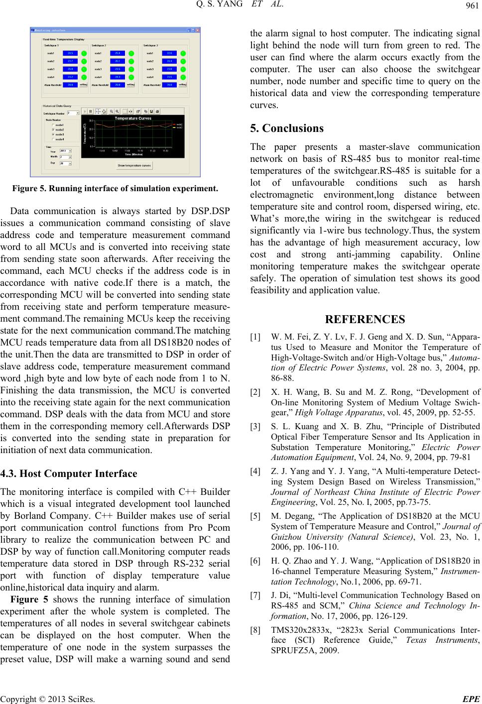 Q. S. YANG ET AL. Copyright © 2013 SciRes. EPE 961 Figure 5. Running interface of simulation experiment. Data communication is always started by DSP.DSP issues a communication command consisting of slave address code and temperature measurement command word to all MCUs and is converted into receiving state from sending state soon afterwards. After receiving the command, each MCU checks if the address code is in accordance with native code.If there is a match, the corresponding MCU will be converted into sending state from receiving state and perform temperature measure- ment command.The remaining MCUs keep the receiving state for the next communication command.The matching MCU reads temperature data from all DS18B20 nodes of the unit.Then the data are transmitted to DSP in order of slave address code, temperature measurement command word ,high byte and low byte of each node from 1 to N. Finishing the data transmission, the MCU is converted into the receiving state again for the next communication command. DSP deals with the data from MCU and store them in the corresponding memory cell.Afterwards DSP is converted into the sending state in preparation for initiation of next data communication. 4.3. Host Computer Interface The monitoring interface is compiled with C++ Builder which is a visual integrated development tool launched by Borland Company. C++ Builder makes use of serial port communication control functions from Pro Pcom library to realize the communication between PC and DSP by way of function call.Monitoring computer reads temperature data stored in DSP through RS-232 serial port with function of display temperature value online,historical data inquiry and alarm. Figure 5 shows the running interface of simulation experiment after the whole system is completed. The temperatures of all nodes in several switchgear cabinets can be displayed on the host computer. When the temperature of one node in the system surpasses the reset value, DSP will make a warning sound and send the alarm signal to host computer. The indicating signal light behind the node will turn from green to red. The user can find where the alarm occurs exactly from the computer. The user can also choose the switchgear number, node number and specific time to query on the historical data and view the corresponding temperature curves. 5. Conclusions The paper presents a master-slave communication network on basis of RS-485 bus to monitor real-time temperatures of the switchgear.RS-485 is suitable for a lot of unfavourable conditions such as harsh electromagnetic environment,long distance between temperature site and control room, dispersed wiring, etc. What’s more,the wiring in the switchgear is reduced significantly via 1-wire bus technology.Thus, the system has the advantage of high measurement accuracy, low cost and strong anti-jamming capability. Online monitoring temperature makes the switchgear operate safely. The operation of simulation test shows its good feasibility and application value. REFERENCES [1] W. M. Fei, Z. Y. Lv, F. J. Geng and X. D. Sun, “Appara- tus Used to Measure and Monitor the Temperature of High-Voltage-Switch and/or High-Voltage bus,” Automa- tion of Electric Power Systems, vol. 28 no. 3, 2004, pp. 86-88. [2] X. H. Wang, B. Su and M. Z. Rong, “Development of On-line Monitoring System of Medium Voltage Swich- gear,” High Voltage Apparatus, vol. 45, 2009, pp. 52-55. [3] S. L. Kuang and X. B. Zhu, “Principle of Distributed Optical Fiber Temperature Sensor and Its Application in Substation Temperature Monitoring,” Electric Power Automation Equipment, Vol. 24, No. 9, 2004, pp. 79-81 [4] Z. J. Yang and Y. J. Yang, “A Multi-temperature Detect- ing System Design Based on Wireless Transmission,” Journal of Northeast China Institute of Electric Power Engineering, Vol. 25, No. I, 2005, pp.73-75. [5] M. Degang, “The Application of DS18B20 at the MCU System of Temperature Measure and Control,” Journal of Guizhou University (Natural Science), Vol. 23, No. 1, 2006, pp. 106-110. [6] H. Q. Zhao and Y. J. Wang, “Application of DS18B20 in 16-channel Temperature Measuring System,” Instrumen- tation Technology, No.1, 2006, pp. 69-71. [7] J. Di, “Multi-level Communication Technology Based on RS-485 and SCM,” China Science and Technology In- formation, No. 17, 2006, pp. 126-129. [8] TMS320x2833x, “2823x Serial Communications Inter- face (SCI) Reference Guide,” Texas Instruments, SPRUFZ5A, 2009. p |