Paper Menu >>
Journal Menu >>
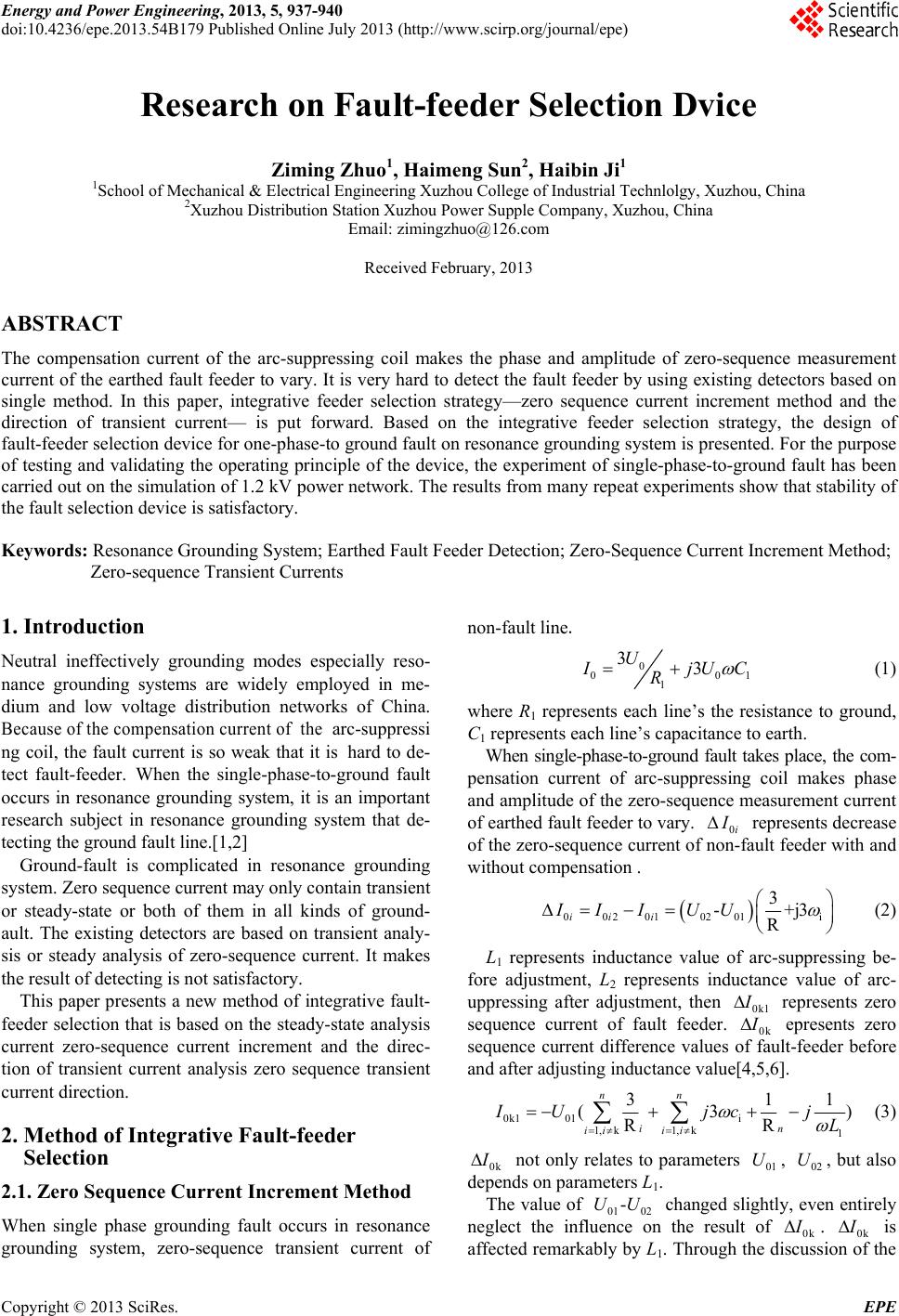 Energy and Power Engineering, 2013, 5, 937-940 doi:10.4236/epe.2013.54B179 Published Online July 2013 (http://www.scirp.org/journal/epe) Research on Fault-feeder Selection Dvice Zimin g Zhuo1, Haimeng Sun2, Haibin Ji1 1School of Mechanical & Electrical Engineering Xuzhou College of Industrial Technlolgy, Xuzhou, China 2Xuzhou Distribution Station Xuzhou Power Supple Company, Xuzhou, China Email: zimingzhuo@126.com Received February, 2013 ABSTRACT The compensation current of the arc-suppressing coil makes the phase and amplitude of zero-sequence measurement current of the earthed fault feeder to vary. It is very hard to detect the fault feeder by using existing detectors based on single method. In this paper, integrative feeder selection strategy—zero sequence current increment method and the direction of transient current— is put forward. Based on the integrative feeder selection strategy, the design of fault-feeder selection device for one-phase-to ground fault on resonance grounding system is presented. For the purpose of testing and validating the operating principle of the device, the experiment of single-phase-to-ground fault has been carried out on the simulation of 1.2 kV power n etwork. The resu lts from many repeat experiments show that stability of the fault selection device is satisfactory. Keywords: Resonance Grounding System; Earthed Fault Feeder Detection; Zero-Sequence Current Increment Method; Zero-sequence Transient Currents 1. Introduction Neutral ineffectively grounding modes especially reso- nance grounding systems are widely employed in me- dium and low voltage distribution networks of China. Because of the compensation current of the arc-suppressi ng coil, the fault current is so weak that it is hard to de- tect fault-feeder. When the single-phase-to-ground fault occurs in resonance grounding system, it is an important research subject in resonance grounding system that de- tecting the ground fault line.[1,2] Ground-fault is complicated in resonance grounding system. Zero sequence current may only contain transient or steady-state or both of them in all kinds of ground- ault. The existing detectors are based on transient analy- sis or steady analysis of zero-sequence current. It makes the result of detecting is not satisfactory. This paper presents a new method of integrative fault- feeder selection that is based on the steady-state analysis current zero-sequence current increment and the direc- tion of transient current analysis zero sequence transient current direction. 2. Method of Integrative Fault-feeder Selection 2.1. Zero Sequence Current Increment Method When single phase grounding fault occurs in resonance grounding system, zero-sequence transient current of non-fault line. 0 0 1 33 U0 1 I jU C R (1) where R1 represents each line’s the resistance to ground, C1 represents each line’s capacitance to earth. When single-phase-to-ground fault takes place, the com- pensation current of arc-suppressing coil makes phase and amplitude of the zero-sequence measurement current of earthed fault feeder to vary. 0 i I represents decrease of the zero-sequence current of non-fault feeder with and without compensation . 00201 0201i 3 -+j3 R ii i II IUU (2) L1 represents inductance value of arc-suppressing be- fore adjustment, L2 represents inductance value of arc- uppressing after adjustment, then 0k1 I represents zero sequence current of fault feeder. 0k I epresents zero sequence current difference values of fault-feeder before and after adjusting indu ctance value[4,5,6]. 0k1 01i 1, k1, k1 31 (3 RR nn in ii ii IUjc j L 1 ) (3) 0k I not only relates to parameters , , but also depends on param et e rs L1. 01 U 02 U The value of 0102 changed slightly, even entirely neglect the influence on the result of 0k -UU I . 0k I is affected remarkably by L1. Through the discussion of the Copyright © 2013 SciRes. EPE 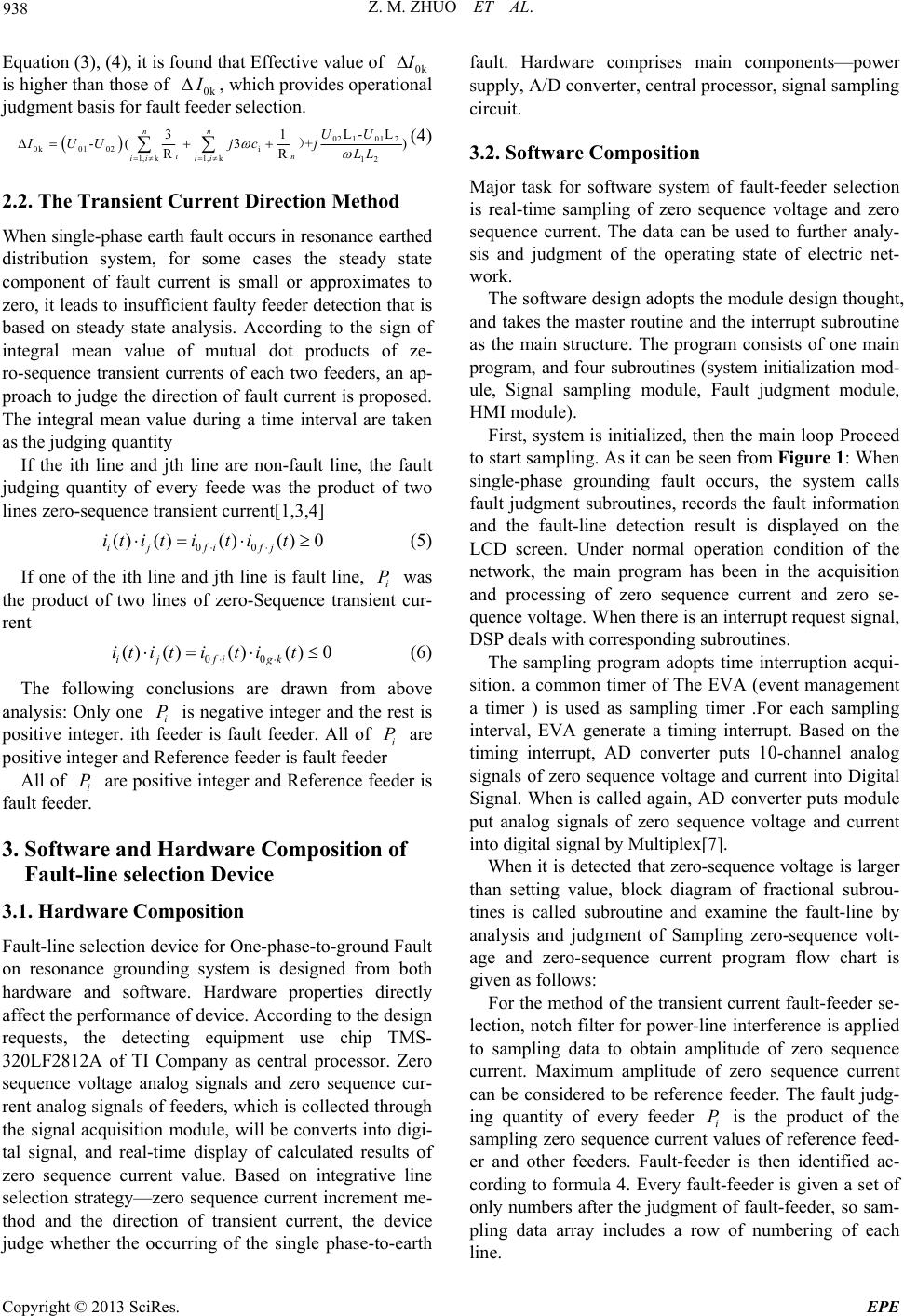 Z. M. ZHUO ET AL. 938 Equation (3), (4), it is found that Effective value of 0k I is higher than those of 0k I , which provides operational judgment basis for fault feeder selection. 02 101 2 L) P 0k01 02i 1, k12 L- 31 -(3 + RR in ii UU IUUjc jLL ) 1,k nn ii f i ()t i (4) 2.2. The Transient Current Direction Method When single-phase earth fault occurs in resonance earthed distribution system, for some cases the steady state component of fault current is small or approximates to zero, it leads to insufficient faulty feeder detection th at is based on steady state analysis. According to the sign of integral mean value of mutual dot products of ze- ro-sequence transient currents of each two feeders, an ap- proach to judge the direction of fault curren t is proposed. The integral mean value during a time interval are taken as the judging quantity If the ith line and jth line are non-fault line, the fault judging quantity of every feede was the product of two lines zero-sequence transient current[1,3,4] 00 ()()()() 0 iji fj it itt it (5) If one of the ith line and jth line is fault line, i was the product of two lines of zero-Sequence transient cur- rent P 00 ()()() 0 ijfi gk it it it (6) The following conclusions are drawn from above analysis: Only one i is negative integer and the rest is positive integer. ith feeder is fault feeder. All of i are positive integer and Reference feeder is fault feeder P All of i are positive integer an d Reference feeder is fault feeder. P 3. Software and Hardware Composition of Fault-line selection Device 3.1. Hardware Composition Fault-line selection device for One-phase-to-ground Fault on resonance grounding system is designed from both hardware and software. Hardware properties directly affect the performance of device. According to the design requests, the detecting equipment use chip TMS- 320LF2812A of TI Company as central processor. Zero sequence voltage analog signals and zero sequence cur- rent analog signals of feeders, which is collected through the signal acquisition module, will be converts into digi- tal signal, and real-time display of calculated results of zero sequence current value. Based on integrative line selection strategy—zero sequence current increment me- thod and the direction of transient current, the device judge whether the occurring of the single phase-to-earth fault. Hardware comprises main components—power supply, A/D converter, central processor, signal sampling circuit. 3.2. Software Composition Major task for software system of fault-feeder selection is real-time sampling of zero sequence voltage and zero sequence current. The data can be used to further analy- sis and judgment of the operating state of electric net- work. The software design adopts the module design thought, and takes the master routine and the interrupt subroutine as the main structure. The program consists of one main program, and four subroutines (system initialization mod- ule, Signal sampling module, Fault judgment module, HMI module). First, system is initialized, then the main loop Proceed to start sampling. As it can be seen from Figure 1: When single-phase grounding fault occurs, the system calls fault judgment subroutines, records the fault information and the fault-line detection result is displayed on the LCD screen. Under normal operation condition of the network, the main program has been in the acquisition and processing of zero sequence current and zero se- quence voltage. When there is an interrupt request signal, DSP deals with corresponding subroutines. The sampling program adopts time interruption acqui- sition. a common timer of The EVA (event management a timer ) is used as sampling timer .For each sampling interval, EVA generate a timing interrupt. Based on the timing interrupt, AD converter puts 10-channel analog signals of zero sequence voltage and current into Digital Signal. When is called again, AD converter puts module put analog signals of zero sequence voltage and current into digital signal by Multip lex[7]. When it is detected that zero-sequence voltage is larger than setting value, block diagram of fractional subrou- tines is called subroutine and examine the fault-line by analysis and judgment of Sampling zero-sequence volt- age and zero-sequence current program flow chart is given as follows: For the method of the transient current fault-feeder se- lection, notch filter for power-line interference is applied to sampling data to obtain amplitude of zero sequence current. Maximum amplitude of zero sequence current can be considered to be reference feeder. The fault judg- ing quantity of every feeder i is the product of the sampling zero sequence current values of reference feed- er and other feeders. Fault-feeder is then identified ac- cording to formula 4. Every fault-feeder is given a set of only numbers after the judgment of fault-feeder, so sam- pling data array includes a row of numbering of each line. P Copyright © 2013 SciRes. EPE 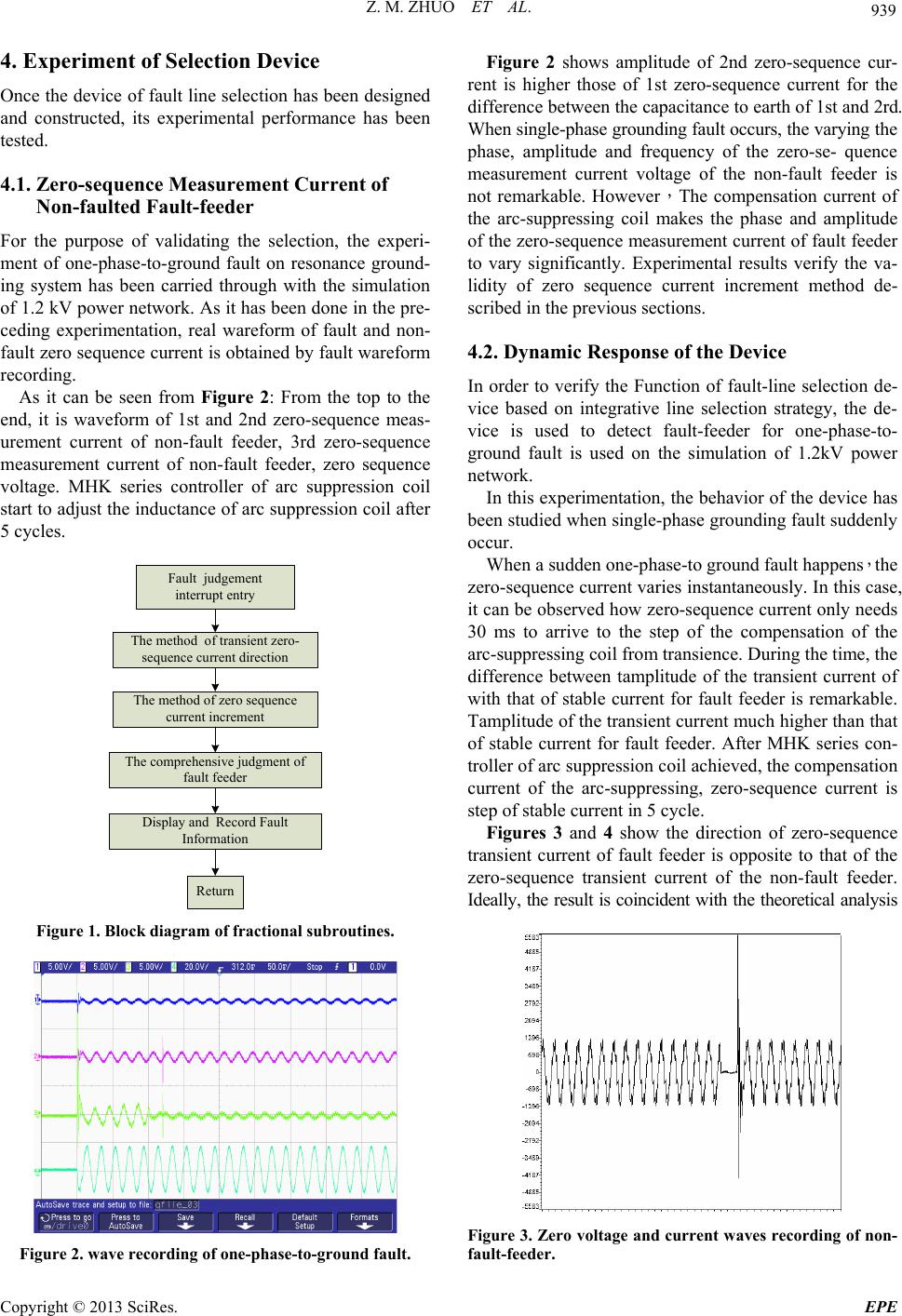 Z. M. ZHUO ET AL. 939 4. Experiment of Selection Device Once the device of fault line selection has been designed and constructed, its experimental performance has been tested. 4.1. Zero-sequence Measurement Current of Non-faulted Fault-feeder For the purpose of validating the selection, the experi- ment of one-phase-to-ground fault on resonance ground- ing system has been carried through with the simulation of 1.2 kV power network. As it has been done in the pre- ceding experimentation, real wareform of fault and non- fault zero sequence current is obtained by fault wareform recording. As it can be seen from Figure 2: From the top to the end, it is waveform of 1st and 2nd zero-sequence meas- urement current of non-fault feeder, 3rd zero-sequence measurement current of non-fault feeder, zero sequence voltage. MHK series controller of arc suppression coil start to adjust the inductance of arc suppression co il after 5 cycles. Fault judgement interrupt ent ry The method of transient zero- sequence current direction The method of zerosequence current increment The comprehensive judgment of fault feeder Display and Record Fault Information Return Figure 1. Block diagram of fractional subroutines. Figure 2. wave recording of one-phase-to-ground fault. Figure 2 shows amplitude of 2nd zero-sequence cur- rent is higher those of 1st zero-sequence current for the difference between the capacitance to earth of 1st and 2rd. When single-phase grounding fault occurs, the varying the phase, amplitude and frequency of the zero-se- quence measurement current voltage of the non-fault feeder is not remarkable. However,The compensation current of the arc-suppressing coil makes the phase and amplitude of the zero-sequence measurement current of fault feeder to vary significantly. Experimental results verify the va- lidity of zero sequence current increment method de- scribed in the previous sections. 4.2. Dynamic Response of the Device In order to verify the Function of fault-line selection de- vice based on integrative line selection strategy, the de- vice is used to detect fault-feeder for one-phase-to- ground fault is used on the simulation of 1.2kV power network. In this experimentation, the behavior of the device has been studied when single-ph ase grounding fault sudd enly occur. When a sudden one-pha se-to ground fault hap pens,the zero-sequence current varies instantaneously. In this case, it can be observed how zero-sequence current only needs 30 ms to arrive to the step of the compensation of the arc-suppressing coil from transience. During the time, the difference between tamplitude of the transient current of with that of stable current for fault feeder is remarkable. Tamplitude of the transient cu rrent much higher than th at of stable current for fault feeder. After MHK series con- troller of arc suppression coil ach iev ed, the compensation current of the arc-suppressing, zero-sequence current is step of stable current in 5 cycle. Figures 3 and 4 show the direction of zero-sequence transient current of fault feeder is opposite to that of the zero-sequence transient current of the non-fault feeder. Ideally, the result is coincident with the theoretical analysis Figure 3. Zero voltage and current waves recording of non- fault-feeder. Copyright © 2013 SciRes. EPE 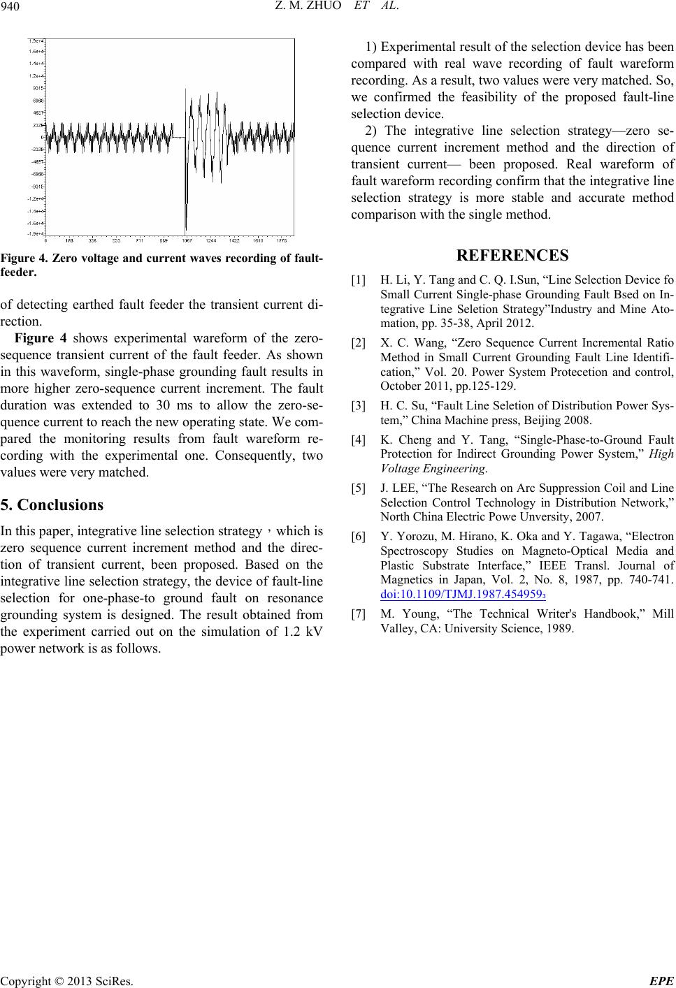 Z. M. ZHUO ET AL. Copyright © 2013 SciRes. EPE 940 1) Experimental result of the selection device has been compared with real wave recording of fault wareform recording. As a result, two values were very matched. So, we confirmed the feasibility of the proposed fault-line selection d ev i ce. 2) The integrative line selection strategy—zero se- quence current increment method and the direction of transient current— been proposed. Real wareform of fault wareform recording confirm that the in tegrative line selection strategy is more stable and accurate method comparison with the single method. REFERENCES Figure 4. Zero voltage and current waves recording of fault- feeder. [1] H. Li, Y. Tang and C. Q. I.Sun, “Line Selection Device fo Small Current Single-phase Grounding Fault Bsed on In- tegrative Line Seletion Strategy”Industry and Mine Ato- mation, pp. 35-38, April 2012. of detecting earthed fault feeder the transient current di- rection. Figure 4 shows experimental wareform of the zero- sequence transient current of the fault feeder. As shown in this waveform, single-phase grounding fault results in more higher zero-sequence current increment. The fault duration was extended to 30 ms to allow the zero-se- quence current to reach the new operating state. We com- pared the monitoring results from fault wareform re- cording with the experimental one. Consequently, two values were very matched. [2] X. C. Wang, “Zero Sequence Current Incremental Ratio Method in Small Current Grounding Fault Line Identifi- cation,” Vol. 20. Power System Protecetion and control, October 2011, pp.125-129. [3] H. C. Su, “Fault Line Seletion of Distribution Power Sys- tem,” China Machine press, Beijing 2008. [4] K. Cheng and Y. Tang, “Single-Phase-to-Ground Fault Protection for Indirect Grounding Power System,” High Voltage Engineering. [5] J. LEE, “The Research on Arc Suppression Coil and Line Selection Control Technology in Distribution Network,” North China Electric Powe Unversity, 2007. 5. Conclusions In this paper, integrative line selection strategy,which is zero sequence current increment method and the direc- tion of transient current, been proposed. Based on the integrative line selectio n strategy, the device of fault-line selection for one-phase-to ground fault on resonance grounding system is designed. The result obtained from the experiment carried out on the simulation of 1.2 kV power network is as follows. [6] Y. Yorozu, M. Hirano, K. Oka and Y. Tagawa, “Elect ron Spectroscopy Studies on Magneto-Optical Media and Plastic Substrate Interface,” IEEE Transl. Journal of Magnetics in Japan, Vol. 2, No. 8, 1987, pp. 740-741. doi:10.1109/TJMJ.1987.4549593 [7] M. Young, “The Technical Writer's Handbook,” Mill Valley, CA: University Science, 1989. |