 Communications and Network, 2013, 5, 361-366 http://dx.doi.org/10.4236/cn.2013.53B2066 Published Online September 2013 (http://www.scirp.org/journal/cn) An Enhanced Difference Method for Multi-objective Model of Cellular Base Station Antenna Configurations Xiaofei Wang, Zhipeng Jiang, Suixiang Gao School of Mathematical Sciences, University of CAS, Beijing, China Email: wangxiaofei110@mails.ucas.ac.cn, lstjzp07@aliyun.com, sxgao@ucas.ac.cn Received July, 2013 ABSTRACT In this paper, we propose a fine-grained gr id-based multi-objectiv e model which aims at optimizing base station anten- nas' configurations, such as transmit power, antenna tilt and antenna azimuth, in order to upgrading network perform- ance in cellular networks. As the model is non-convex, non -smooth and discrete and computationally expensive, we use decomposition method to solve the MOP problem. We mainly focus on addressing the scalarized sub-problem after decomposition. For the scalarized sub-problem, we propose an enhanced difference method. First, difference of each component is calculated, which provides the guidance of optimization. Then an OPSO is applied to search the optimal step length. The method is applied to GSM network optimization on an area in Beijing. The effect of the application shows that proposed method has a good performance, and is effective/efficient to solve mobile network optimization problems. Keywords: Mobile Network Optimization; Multi-objective Optimization; Decomposition, Difference Method, Particle Swarm Optimization 1. Introduction Wireless networks such as GSM, UMTS etc. are based on the same cellular concept. A cellular network is a ra- dio network distributed over land areas called cells, each served by at least one fixed-location transceiver, known as a cell site or base station antenna. Due to the high costs and the scarcity of radio resources, an accurate and efficient mobile network planning appears of outmost importance. With the rapid growth of network size and number of users, efficient quantitative methods to sup- port decisions for base station (BS) location have become essential. This need is now even more acute due to the increased complexity of the system and the number of parameters that must be considered [2]. In order to im- prove the quality of service (QoS) in cellular network s, it is very important to implement the network planning and optimization in cellular networks. Network planning re- fers to the process of designing network structure and topology subject to various design requirements. Net- work optimization amounts to finding a network con- figuration to achieve the best possible performance. In order to improve the QOS of a cellular network, some factors have to be considered, e.g. upgrading cov- erage rate, decreasing interference, increasing coverage continuity and enhancing cells’ traffic equilibrium. In real system planning, optimizing BS configuration can often be more critical than BS location since service pro- viders may have a very limited set of candidate sites due to authority constraints on new antenna installation and on electromagnetic pollution in urban areas. So they are usually very interested in optimizing the QOS with the available BSs by adjusting their configurations, adding new BSs only when it is strictly necessary. In detailed planning, making major changes in net- work topology and layout is typically not an acceptable option for an operator. Instead, the goal is to optimize antennas’ key configuration parameters [7]. Meanwhile, the optimization of every one of these parameters is af- fected by the other parameters and other antennas. Be- cause of this, it is difficult and even impossible to opti- mize the three configuration parameters by a manual approach. Automated network planning and optimization through mathematical model and algorithms allow op- erators to better deal with the complexity of cellular network optimization, a task that is often beyond the reach of a manual approach. In addition to making the network optimization process time-efficient, planning tools incorporating automated optimization can signifi- cantly reduce network deployment and maintenance costs. There have been many works on cellular networks planning and op timization. Almost all the prev ious work s establish a model with a discrete solution space and C opyright © 2013 SciRes. CN  X. F. WANG ET AL. 362 based on few test points. But as mentioned in [8], the optimization conducted on few test points can’t ensure the same good performance for other region. Besides, in order to improve the QoS of a cellular network, some objectives/factors have to be considered simultaneously, e.g. upgrading coverage rate, decreasing interference, increasing coverage continuity and enhancing cells' traf- fic equilibrium. These factors or objectives are often de- pendent and conflict. For instance, decreasing the transmit power reduce the cell overlap and interference. On the other hand, coverage problems will arise if the transmit power becomes too low. So, a multi-objective optimization problem should be considered to improve the QoS of mobile network. In this paper, we propose a multi-objective optimization model of QOS and base station antenna configurations with fine-grained grid division developed in [8], and an enhanced difference method is designed for the proposed MOP. This paper is organized as follows. Section 2 discusses the cellular networks planning and optimization prob- lems on previous work. In Section 3, a multi-objective optimization model of QOS and base station antenna configurations is proposed in cellular networks. In Sec- tion 4, we give the enhanced difference method to solve the proposed MOP model. Computational results ob- tained with realistic instances are reported and discussed in Section 5. The paper is then concluded in Section 6. 2. Previous Work Many previous works have discussed the optimization of the location and co nfiguration of base stations. In [2], the authors proposed discrete optimization models which consider the signal-to-interference ratio as quality measure and algorithms aimed at supporting the decisions in the process of planning where to locate new BSs. The similar methods are arisen in [3-5], [15]. But all these studies are about the positio n on which the BSs are installed without considering the adjustment of the an- tennas' configuration. In [6] the authors gave a basic model for pilot power optimization subject to a full cov- erage constraint as well as its extended version which considers various coverage levels and to consider user traffic distribution over the network. In [7] automated optimization of service coverage and radio base station antenna configuration is addressed and three key con- figuration parameters: transmit power of the common pilot channel (CPICH), antenna tilt and antenna azimuth are considered. The optimization targ et is minimizing the total CPICH power under the constraint that every bin (Each bin is a test point) is in the coverage area of at least one cell. In [9-11], a mathematical mixed-integer pro- gramming model for planning cost-efficient radio net- works under network quality constraints and some net- work planning methods based on this model are pre- sented. All these studies suppose that a little area with a given amount of traffic can be considered as a test point and the whole optimization area is denoted by all this kind of points. Meanwhile, all these studies give models with constraints like that the signal received by all the test points must be under the given constraints (i.e. the signal strength received by every point have to be strong enough, and the signal to in terf erence r atio of ev ery poin t must be greater than a given threshold.). Then they opti- mized some other performance parameters (e.g. mini- mizing the cost or total transmit power) with this con- straint and some other constraints. But in real application, constraints like that the signal received by all the test points must be under the given constraints may not be satisfied no matter how the antennas' con figuration of the network being set. In [12] various parameters of cellular base station (BS) placement problem such as site coordinates, transmit power, height and tilt angle are determined using evolu- tionary multi-objective algorithm to obtain better com- promised solutions. And the maximization of service coverage and minimization of cost are considered as conflicting objectives by satisfying in equality constraints such as handover, traffic demand and overlap. In [13] the authors address the design of the network which has been formulated as a multi-objective constrained combinato- rial optimization problem and propose a genetic algo- rithm that aims to approximate the Pareto frontier of the problem. But the detailed formulas of the objectives are not given in these studies. In [14] the authors address the problem of capacity op- timization in a Universal Mobile Telecommunication System (UMTS) radio network and present an optimiza- tion algorithm for finding th e best settings of the antenna tilt and common pilot channel power of the base station s. But only an algorithm is presented in this paper without any model. 3. A Multi-objective Model of QoS and Base Station Antenna Configurations In the section, A multi-objective optimization model is proposed. As mentioned in introduction sectio n, there are several indicators that reflect performance of the network, such as interference, coverage rate, the connectivity of pri- mary service area and traffic balance. In this paper, the objectives we consider are coverage rate, interference and the connectiv ity of primary serv ice, and the variables are antenna's azimuth, tilt and transmit power. Traffic balances are considered as constraints, because the dis- tribution of grid traffic varies from time to time, it's very Copyright © 2013 SciRes. CN  X. F. WANG ET AL. 363 difficult to handle all cases. In order to optimize a rec- tangle region by adjusting some antenn as' para meters, the region surrounding must be considered. Otherwise, after optimization, the objectives of region get improved but the region surrounding may get worse. Besides consider- ing the optimization region, we also take account of the region around as protect region. The main goal is to optimize the objectives of optimi- zation region by adjusting antennas' parameter and meanwhile to avoid the objectives of protect regions get- ting worse. In add ition, antennas must not be ov erloaded. The antennas selected to be adjusted are determined in advance. 3.1. Multi-objective Model Consider a rectangle optimization region Z and corre- sponding protect region ' , divided into I and J grids with identical or different size respectively. We assume the strength of the received signal from an antenna at all the points in a grid is identical and the total traffic of every grid is received only by one antenna. In order to make the hypothesis be rational, the grid size have to be small enough. Suppose there are K antennas that can affect the region and ' . An antenna affect a region if the strength of the received signal in at least one grid in the region from this antenna is greater than a given threshold (e.g. -104dBm) and the strength of the received signal of all the grids from each antenna can be estimated according to empirical propagation models such as Hata and COST-231 or to more precise but computationally intensive ray tracing techniques. Let the strength of the received signal in grid i from antenna k be ik . If the strength of the received signal in grid i from antenna k is the strongest in all antennas which can affect the grid i, then antenna k is called the master antenna of grid i and the strength of the received signal from antenna k is called the master strength. Let i be the geographic neighbor of grid i. The antenna is the master antenna of grid i. P N i k The proposed multi-objective optimization model ( OP ) is given below: is a very large number. R is set of adjusted antenna s. is the set of antennas, traffic balance of which are considered. u t represents the traffic of grid . target is strength threshold. TK uP K contains K and TK. AK and TK are determined by K and propagation model. is total traffic received by an- tenna k. 0 and represent the traffic received from optimization region and protect region under the adjusted antenna's configure 0 k TT(Tx()Tx ) and x. k L is the maximum traffic load of antenna k, which is determined by the number of antenna's frequency channels and maximum capacity of per channel. 0 is the existing antennas’ configuration of the network. 123 target 0 0 0 ' 0 ' 0 min( )(( ),( ),( )) ..( ), |9|/ , argmax( ), (()/ ()) (()/ ()) u v i j T x uuk uu v vN ukAKuk i iI ik ik kAk iI i iI j jJ jk jk kAk jJ j j fxfxfxf x thRP PxuIJ gk kRuIJ kPxu hW PxPx E gB hW PxPx E g IJ ' 0 0 () (), J kk kk B TTTxTxMLk TK xX where 1 2 2 3 {|} 1 () || ()(1 (()/())) 1 () || () i u i iI ik ik kAK iI i iI ku uI Jkk fx h I fxPxPx fx g I Tx t ''' 000000 ,,,,,WEBWEB are thresholds that represent the objective function values of optimization region and protect region under the existing antenna configuration of the network respectively. 3.2. Variables, Objectives and Constraints Three key base station antenna con figuration parameters, transmit power, antenna tilt and antenna azimuth, are considered in this model. Then the decision variable x is set as ' 111 (,,,, , ,) KKK pp , where i is the antenna azimuth, and i 'i is antenna tilt, i is transmit power. p is the rectangle boundary set of x. As mentioned in [1], each antenna is configured by some engineering parameters and the adjustment of every con- figuration parameters is limited in a special range. There are three objective functions in this mod el. First objective is to minimize the weak coverage rate of opti- mization region Z. If the master strength of grid i is less than a given threshold target (i.e. -90dBm), the grid i is called weak-covered grid because master strength is too weak to be received by receivers. Second objective is to minimize the interference from other antenna. We evalu- P Copyright © 2013 SciRes. CN  X. F. WANG ET AL. 364 ate this objective by considering the ratio of interference energy and total receive energy. The third objective is to reduce the boundary grid rate, which is to decrease the switching possibility. When a calling moves from a grid in which the master antenna is antenna k to a grid in which the master antenna is antenna q and kq , the access antenna of this calling may switch from k to q. The dropped possibility of the calling is increasing dur- ing the process of switching. So in order to decreasing the call dropping possibility cau sed by the switching, the rate of cell boundary g rids has to be re d uced. Constrains (4)-(6) represent that optimal solution must outperform the existing configuration in terms of opti- mization region. Constrains (7)-(9) represent that the objectives of protect region must not get worse after op- timization. Constrains (10) represent that antenna traffic must not be exceed maximum load. In practical optimi- zation, objectives in optimization region may conflict with the one in protect region. And if we keep the con- straint strictly satisfied, there may be no feasible solution. Thus, in this paper, we consider the relaxation form of MOP and get OP . For the sake of saving space, the right terms in constraints (7)-(9) are multiplied by (1 ) . If 0 , OP and OP are the same. 4. Enhanced Difference Method The MOP is difficult to solve because it is nonconvex nonsmooth and discrete. And the function evaluation is computationally expensive, so we choose a decomposi- tion-based multi-objective optimization method. By de- composition, the MOP is transformed into single objec- tive problem. Thus, the classical single optimization methods are used to solve it in a fast convergence. In this paper, we use the popular decomposition-based framework-MOEA/D [16] to decompose the MOP. In this paper, we mainly consider approaches for subprob- lems, which are taken as an option in [16]. The mail loop in MOEA/D is used to help subproblems jump out of local optimal. As the sub-problem is also a nonconvex, nonsmooth and discrete, it's difficult to solve it by classical gradi- ent-based methods. We use the difference instead of gra- dient to guide the search, but the difference is used in a different way, no the same with coordinate rotation method. Thus, an enhanced difference method is pro- posed. First the penalty NBI method is applied to trans- form the MOP into single objective function. Then the difference of every component is calculated. After that component difference is modified into improved differ- ence matrix (Algorithm 2). In the last, we use OPSO [17] to get the step length with the guide of improved differ- ence matrix (A lgorithm 1); We list the proposal method -- Enhanced Difference Method below: Algorithm 1 Enhanced Difference Method Input: weight vector , reference point , penalty parameter * z Output: optimal solution Step 1. Initiate first solution 0,0 t xxt Step 2. Use Penalty NBI method, scalarize the MOP * 121 * 21 || (())|| (), || || ||()() || T tfx z gxdd d dfxzd Step 3 Calculate improved difference matrix of , see Algorithm 2 t D Step 4. Apply OPSO to search the best step size array for improved difference of current solution x, which is to solve the following optimization: min(( )) .. 0 tttT k t ii t i xD st u N where i is max step size for dimension i, is the improved difference matrix. ut D Step 5. let 1() tttT k xD , . If stopping condition is satisfied, then stop and output :tt1 t . Other- wise, go to Step 2. Algorithm 2 Improved Difference Matrix Input: a scalarized function () t x Output: improved difference matrix t D Step 1. Initialize 0 t D , and initialize max differ- ence matrix 0 t G . Step 2. Calculate each component's forward difference and backward difference: ()()()( , tttt ii ii ii ii ) xe gxgxgxe gg where i is the minimum step length of component i. Step 3. Calculate forward improved value and back- ward improved value max(0,), max(0,) iii pgni g Set ii i Gp . if , let . ii ii i Step 4. for each component i, set npGpsgn( ) iiii i DG , sgn( ) is sign function. In next section, we validate the proposal method with real operational network. 5. Simulation and Application In this section, we apply our model and algorithm on the GSM1800 networks of China Mobile Communications Corporation. The implementation is on a region in Bei- jing. The area of the optimization region Z is 1.1km and the area of protect region is 1.7km 7.5km 7.9km . Copyright © 2013 SciRes. CN 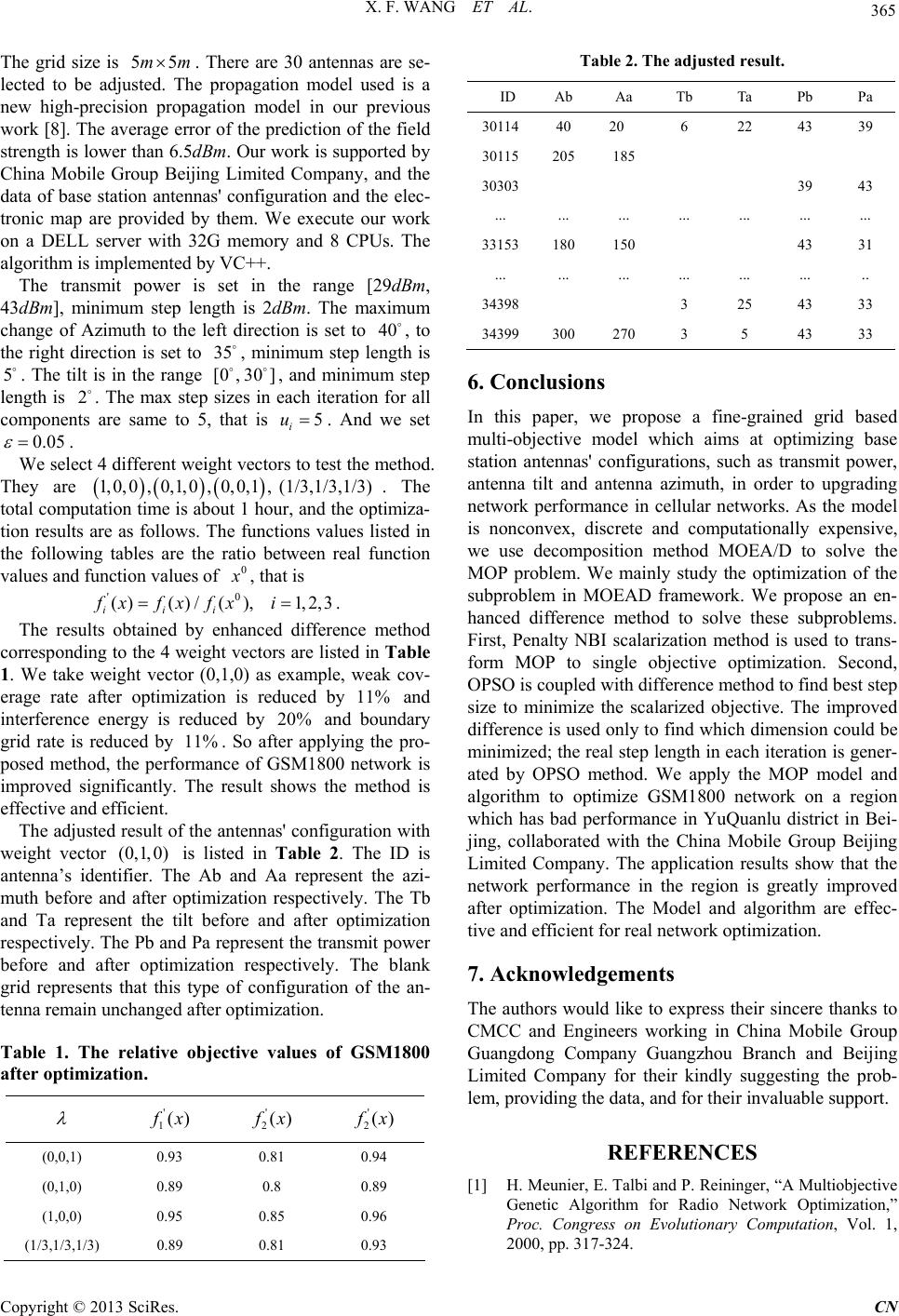 X. F. WANG ET AL. 365 The grid size is . There are 30 antennas are se- lected to be adjusted. The propagation model used is a new high-precision propagation model in our previous work [8]. The average error of the prediction of the field strength is lower than 6.5dBm. Our work is supported by China Mobile Group Beijing Limited Company, and the data of base station antennas' configuration and the elec- tronic map are provided by them. We execute our work on a DELL server with 32G memory and 8 CPUs. The algorithm is implemented by VC++. 55mm The transmit power is set in the range [29dBm, 43dBm], minimum step length is 2dBm. The maximum change of Azimuth to the left direction is set to , to the right direction is set to , minimum step length is . The tilt is in the range , and minimum step length is . The max step sizes in each iteration for all components are same to 5, that is . And we set 40 35 [0 , 530] 2 5 i u 0.05 . We select 4 different weight vectors to test the method. They are . The total computation time is about 1 hour, and the optimiza- tion results are as follows. The functions values listed in the following tables are the ratio between real function values and function values of ,0 , 0,1,0 1,0,0,0,1, (1/3,1/3,1/3) 0 , that is '0 () () ii x fx (0,1,0) /( ),1,2,3 i ffx i. The results obtained by enhanced difference method corresponding to the 4 weight vectors are listed in Table 1. We take weight vector (0,1,0) as example, weak cov- erage rate after optimization is reduced by 11% and interference energy is reduced by and boundary grid rate is reduced by . So after applying the pro- posed method, the performance of GSM1800 network is improved significantly. The result shows the method is effective and efficient. 20% 11% The adju sted result of the anten nas' configuration with weight vector is listed in Table 2. The ID is antenna’s identifier. The Ab and Aa represent the azi- muth before and after optimization respectively. The Tb and Ta represent the tilt before and after optimization respectively. The Pb and Pa represent the transmit power before and after optimization respectively. The blank grid represents that this type of configuration of the an- tenna remain unchanged after optimization. Table 1. The relative objective values of GSM1800 after opti mization . ' 1() x ' 2() x ' 2() x )0,0,1( 0.93 0.81 0.94 )0,1,0( 0.89 0.8 0.89 )1,0,0( 0.95 0.85 0.96 (1/3,1/3,1/3) Table 2. The adjusted result. ID Ab Aa Tb Ta Pb Pa 30114 40 20 6 22 43 39 30115 205 185 30303 39 43 ... ... ... ... ... ... ... 33153180 150 43 31 ... ... ... ... ... ... .. 34398 3 25 43 33 34399300 270 3 5 43 33 6. Conclusions In this paper, we propose a fine-grained grid based multi-objective model which aims at optimizing base station antennas' configurations, such as transmit power, antenna tilt and antenna azimuth, in order to upgrading network performance in cellular networks. As the model is nonconvex, discrete and computationally expensive, we use decomposition method MOEA/D to solve the MOP problem. We mainly study the optimization of the subproblem in MOEAD framework. We propose an en- hanced difference method to solve these subproblems. First, Penalty NBI scalarization method is used to trans- form MOP to single objective optimization. Second, OPSO is coupled with difference method to find best step size to minimize the scalarized objective. The improved difference is used only to find which dimension could be minimized; the real step length in each iteration is gener- ated by OPSO method. We apply the MOP model and algorithm to optimize GSM1800 network on a region which has bad performance in YuQuanlu district in Bei- jing, collaborated with the China Mobile Group Beijing Limited Company. The application results show that the network performance in the region is greatly improved after optimization. The Model and algorithm are effec- tive and efficient for real network optimization. 7. Acknowledgements The authors would like to express their sincere thanks to CMCC and Engineers working in China Mobile Group Guangdong Company Guangzhou Branch and Beijing Limited Company for their kindly suggesting the prob- lem, providing the data, and for their invaluable support. REFERENCES [1] H. Meunier, E. Talbi and P. Reininger, “A Multiobjective Genetic Algorithm for Radio Network Optimization,” Proc. Congress on Evolutionary Computation, Vol. 1, 2000, pp. 317-324. 0.89 0.81 0.93 Copyright © 2013 SciRes. CN  X. F. WANG ET AL. Copyright © 2013 SciRes. CN 366 [2] E. Amaldi, A. Capone and F. Malucelli, “Planning UMTS Base Station Location: Optimization Models with Power Control and Algorithms,” IEEE Transactions on Wireless Comm, Vol. 2, No. 5, 2003, pp. 939-952. doi:10.1109/TWC.2003.817438 [3] E. Amaldi, A. Capone, F. Malucelli and F. Signori, “Op- timization Models and Algorithms for Downlink UMTS Radio Planning,” Proc. IEEE Wireless Communications and Networking Conf, New Orleans, 20-20 Mar 2003, pp. 827-831. [4] E. Amaldi, A. Capone and F. Malucelli, “Improved Mod- els and Algorithms for UMTS Radio Planning,” Pro- ceedings of IEEE VTC Fall 2001. Atlantic City, 7-11 Oct 2001, pp. 920-924. [5] E. Amaldi, A. Capone and F. Malucelli, “Optimizing Base Station Siting in UMTS Networks,” Proceedings of IEEE VTC Spring 2001, Rhodes, 6-9 May 2001, pp. 2828-2832. [6] I. Siomina and D. Yuan, “Pilot Power Management in WCDMA Networks: Coverage Control with Respect to Traffic Distribution,” Proc. Seventh ACM International Symposium on Modeling, Analysis and Simulation of Wireless and Mobile Systems (MSWiM), New York, 2004, pp. 276-282. [7] I. Siomina, P. Varbrand and D. Yuan, “Automated Opti- mization of Service Coverage and Base Station Antenna Configuration in UMTS Networks,” IEEE Wireless Communications Magazine. Vol. 13, No. 6, 2006, pp. 16-25. doi:10.1109/MWC.2006.275194 [8] T. Guo, S. Gao, et al., “High Precision Coverage Optimi- zation Models and Algorithms for GSM and TD-SCDMA Networks,” IFORS 2011, Melbourne, July 2011. [9] A. Eisenblatter, A. Fugenschuh, H. Geerdes, D. Junglas, T. Koch and A. Martin, “Integer Programming Methods for UMTS Radio Network Planning,” Proc. of WiOpt'04, Cambridge, UK, 2004. [10] A. Eisenblatter, T. Koch, A. Martin, T. Achterberg, A. Fugenschuh, A. Koster, O. Wegel and R. Wessaly, “Modelling Feasible Network Configurations for UMTS,” In: G. Anandalingam, S. Raghavan, Ed., Tele- communications Network Design and Management, Springer US, 2003, pp. 1-23. doi:10.1007/978-1-4757-3762-2_1 [11] A. Eisenblatter, E. Fledderus, A. Fugenschuh, H. Geerdes, B. Heideck, D. Junglas, T. Koch, T. Kurner and A. Mar- tin, “Mathematical Methods for Automatic Optimization of UMTS Radio Networks,” Tech. Rep. D43, IST-2000-28088 Momentum , 2003. [12] N. Lakshminarasimman, S. Baskar, A. Alphones and M. WilljuiceIruthayarajan, “Evolutionary Multiobjective Op- timization of Cellular Base Station Locations Using Modified NSGA-II,” J Wirel Networks, Vol. 17, No. 3, 2011, pp. 597-609. doi: 10.1007/s11276-010-0299-2 [13] H. Meunier, E. Talbi and P. Reininger, “A Multiobjective Genetic Algorithm for Radio Network Optimization,” Proc. Congress on Evolutionary Computation, La Jolla, 16-19 Jul 2000, pp. 317-324. [14] A. Gerdenitsch, M. Toeltsch, S. Jakl and Y. Chong, “A Rule Based Algorithm for Common Pilot Channel and Antenna Tilt Optimization in UMTS FDD Networks,” ETRI Journal. Vol. 26, No. 5, 2004, pp. 437-442. doi:10.4218/etrij.04.0703.0007 [15] F. Gu, H. Liu and M. Li, “Evolutionary Algorithm for the Radio Planning and Coverage Optimization of 3G Cellu- lar Networks,” International Conference on Computa- tional Intelligence and Security, Beijing, 11-14 Dec 2009, pp. 109-113. [16] Q. Zhang and H. Li, “MOEA/D: A multiobjective Evolu- tionary Algorithm Based on Decomposition,” Evolution- ary Computation, IEEE Transactions on, Vol. 11, No. 6, 2007, pp. 712-731. doi:10.1109/TEVC.2007.892759 [17] H. Wang, H. Li, Y. Liu, C. Li and S. Zeng, “Opposi- tion-based Particle Swarm Algorithm with Cauchy Muta- tion,” Evolutionary Computation, 2007. CEC 2007. IEEE Congress on, Singapore, 25-28 Sept 2007, pp. 4750-4756.
|