Paper Menu >>
Journal Menu >>
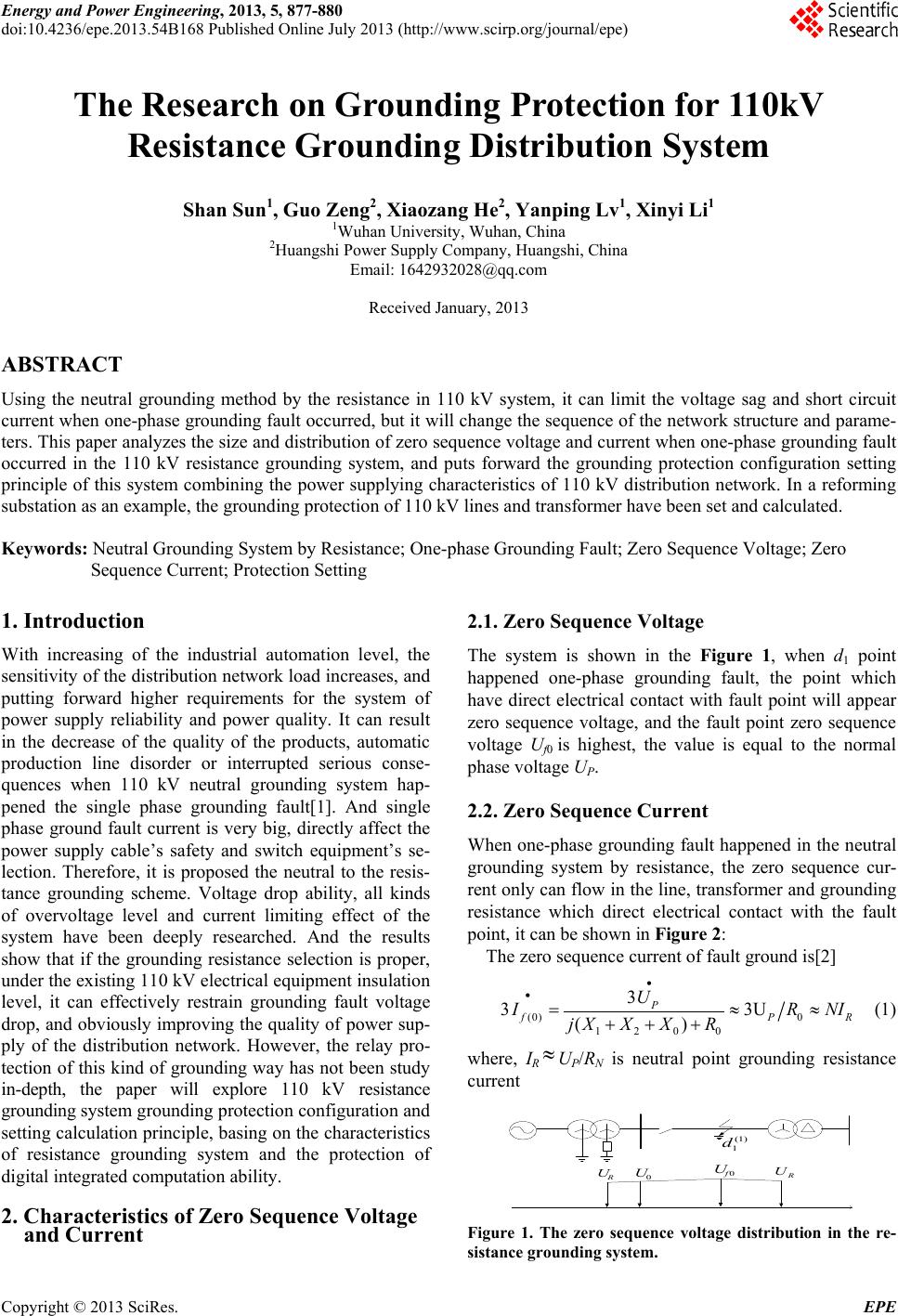 Energy and Power Engineering, 2013, 5, 877-880 doi:10.4236/epe.2013.54B168 Published Online July 2013 (http://www.scirp.org/journal/epe) The Research on Grounding Protection for 110kV Resistance Grounding Distribution System Shan Sun1, Guo Zeng2, X iaozang He2, Yanping Lv1, Xinyi Li1 1Wuhan University, Wuhan, China 2Huangshi Power Supply Company, Huangshi, China Email: 1642932028@qq.com Received January, 2013 ABSTRACT Using the neutral grounding method by the resistance in 110 kV system, it can limit the voltage sag and short circuit current when one-phase grounding fault occurred, but it will change the sequence of the network structure and parame- ters. This paper analyzes the size and distribution of zero sequence voltage and current when one-phase grounding fault occurred in the 110 kV resistance grounding system, and puts forward the grounding protection configuration setting principle of this system combining the power supplying characteristics of 110 kV distribution network. In a reforming substation as an example, the grounding protection of 110 kV lines and transformer have been set and calculated. Keywords: Neutral Grounding System by Resistance; One-phase Grounding Fault; Zero Sequence Voltage; Zero Sequence Current; Protection Setting 1. Introduction With increasing of the industrial automation level, the sensitivity of the distribution network load increases, and putting forward higher requirements for the system of power supply reliability and power quality. It can result in the decrease of the quality of the products, automatic production line disorder or interrupted serious conse- quences when 110 kV neutral grounding system hap- pened the single phase grounding fault[1]. And single phase ground fault current is very big, directly affect the power supply cable’s safety and switch equipment’s se- lection. Therefore, it is proposed the neutral to the resis- tance grounding scheme. Voltage drop ability, all kinds of overvoltage level and current limiting effect of the system have been deeply researched. And the results show that if the grounding resistance selection is proper, under the existing 110 kV electrical equipment insulation level, it can effectively restrain grounding fault voltage drop, and obviously improving the quality of power sup- ply of the distribution network. However, the relay pro- tection of this kind of grounding way has not been study in-depth, the paper will explore 110 kV resistance grounding system grounding protection configuration and setting calculation principle, basing on the characteristics of resistance grounding system and the protection of digital integrated computation ability. 2. Characteristics of Zero Sequence Voltage and Current 2.1. Zero Sequence Voltage The system is shown in the Figure 1, when d1 point happened one-phase grounding fault, the point which have direct electrical contact with fault point will appear zero sequence voltage, and the fault point zero sequence voltage Uf0 is highest, the value is equal to the normal phase voltage UP. 2.2. Zero Sequence Current When one-phase grounding fault happened in the neutral grounding system by resistance, the zero sequence cur- rent only can flow in the line, transformer and grounding resistance which direct electrical contact with the fault point, it can be shown in Figure 2: The zero sequence current of fault ground is[2] (0) 0 120 0 3 33 () PU f PR U I RNI jX XXR (1) where, IR UP/RN is neutral point grounding resistance current 0f U R U 0 U R U (1) 1 d Figure 1. The zero sequence voltage distribution in the re- sistance grounding system. Copyright © 2013 SciRes. EPE 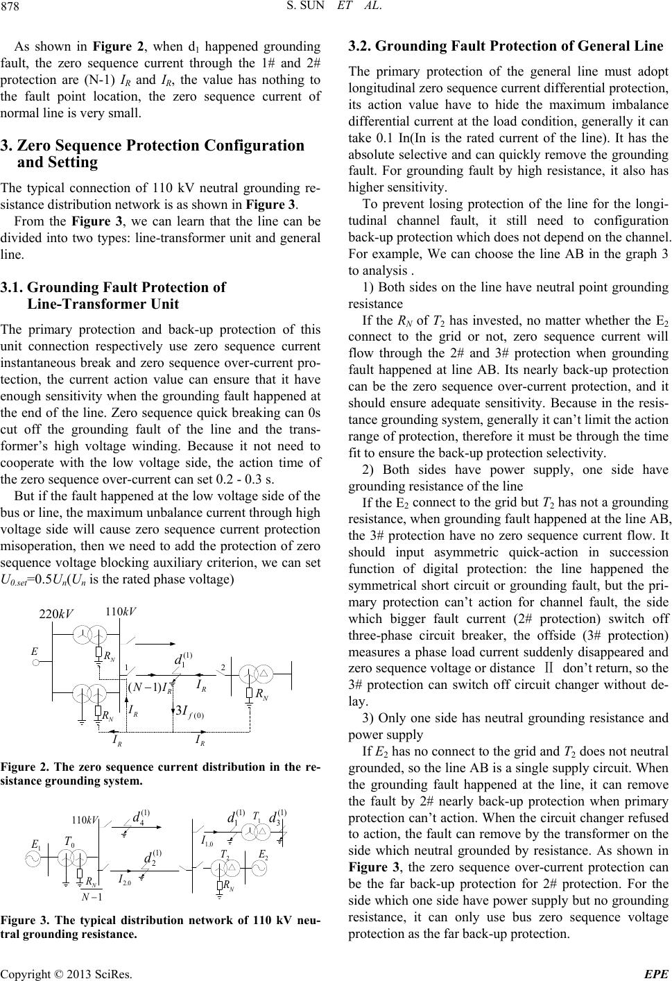 S. SUN ET AL. 878 As shown in Figure 2, when d1 happened grounding fault, the zero sequence current through the 1# and 2# protection are (N-1) IR and IR, the value has nothing to the fault point location, the zero sequence current of normal line is very small. 3. Zero Sequence Protection Configuration and Setting The typical connection of 110 kV neutral grounding re- sistance distribution network is as shown in Figure 3. From the Figure 3, we can learn that the line can be divided into two types: line-transformer unit and general line. 3.1. Grounding Fault Protection of Line-Transformer Unit The primary protection and back-up protection of this unit connection respectively use zero sequence current instantaneous break and zero sequence over-current pro- tection, the current action value can ensure that it have enough sensitivity when the grounding fault happened at the end of the line. Zero sequence quick breaking can 0s cut off the grounding fault of the line and the trans- former’s high voltage winding. Because it not need to cooperate with the low voltage side, the action time of the zero sequence over-current can set 0.2 - 0.3 s. But if the fault happened at the low voltage side of the bus or line, the maximum unbalance current through high voltage side will cause zero sequence current protection misoperation, then we need to add the protection of zero sequence voltage blocking auxiliary criterion, we can set U0.set=0.5Un(Un is the rated phase voltage) N R N R R I (1) R N I R I N R R I (0) 3f I 110kV 220kV E 12 (1) 1 d R I Figure 2. The zero sequence current distribution in the re- sistance grounding system. 1 N R N N R 110kV (1) 1 d (1) 3 d (1) 2 d 0 T 2 E 1 T 2 T (1) 4 d 1.0 I 2.0 I 1 E Figure 3. The typical distribution network of 110 kV neu- tral grounding resistance. 3.2. Grounding Fault Protection of General Line The primary protection of the general line must adopt longitudinal zero sequence current differential protection, its action value have to hide the maximum imbalance differential current at the load condition, generally it can take 0.1 In(In is the rated current of the line). It has the absolute selective and can quickly remove the grounding fault. For grounding fault by high resistance, it also has higher sensitivity. To prevent losing protection of the line for the longi- tudinal channel fault, it still need to configuration back-up protection which does not depend on the channel. For example, We can choose the line AB in the graph 3 to analysis . 1) Both sides on the line have neutral point grounding resistance If the RN of T2 has invested, no matter whether the E2 connect to the grid or not, zero sequence current will flow through the 2# and 3# protection when grounding fault happened at line AB. Its nearly back-up protection can be the zero sequence over-current protection, and it should ensure adequate sensitivity. Because in the resis- tance grounding system, generally it can’t limit the action range of protection, therefore it must be through the time fit to ensure the back-up protection selectivity. 2) Both sides have power supply, one side have grounding resistance of the line If the E2 connect to the grid but T2 has not a grounding resistance, when grounding fault happened at the line AB, the 3# protection have no zero sequence current flow. It should input asymmetric quick-action in succession function of digital protection: the line happened the symmetrical short circuit or grounding fault, but the pri- mary protection can’t action for channel fault, the side which bigger fault current (2# protection) switch off three-phase circuit breaker, the offside (3# protection) measures a phase load current suddenly disappeared and zero sequence voltage or distance Ⅱ don’t return, so the 3# protection can switch off circuit changer without de- lay. 3) Only one side has neutral grounding resistance and power supply If E2 has no connect to the grid and T2 does not neutral grounded, so the line AB is a single supply circuit. When the grounding fault happened at the line, it can remove the fault by 2# nearly back-up protection when primary protection can’t action. When the circuit changer refused to action, the fault can remove by the transformer on the side which neutral grounded by resistance. As shown in Figure 3, the zero sequence over-current protection can be the far back-up protection for 2# protection. For the side which one side have power supply but no grounding resistance, it can only use bus zero sequence voltage protection as the far back-up protection. Copyright © 2013 SciRes. EPE 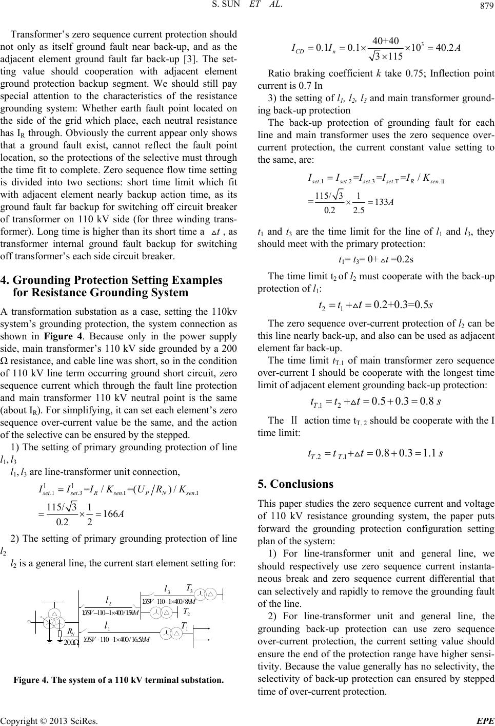 S. SUN ET AL. 879 Transformer’s zero sequence current protection should not only as itself ground fault near back-up, and as the adjacent element ground fault far back-up [3]. The set- ting value should cooperation with adjacent element ground protection backup segment. We should still pay special attention to the characteristics of the resistance grounding system: Whether earth fault point located on the side of the grid which place, each neutral resistance has IR through. Obviously the current appear only shows that a ground fault exist, cannot reflect the fault point location, so the protections of the selective must through the time fit to complete. Zero sequence flow time setting is divided into two sections: short time limit which fit with adjacent element nearly backup action time, as its ground fault far backup for switching off circuit breaker of transformer on 110 kV side (for three winding trans- former). Long time is higher than its short time a , as transformer internal ground fault backup for switching off transformer’s each side circuit breaker. t 4. Grounding Protection Setting Examples for Resistance Grounding System A transformation substation as a case, setting the 110kv system’s grounding protection, the system connection as shown in Figure 4. Because only in the power supply side, main transformer’s 110 kV side grounded by a 200 Ω resistance, and cable line was short, so in the condition of 110 kV line term occurring ground short circuit, zero sequence current which through the fault line protection and main transformer 110 kV neutral point is the same (about IR). For simplifying, it can set each element’s zero sequence over-current value be the same, and the action of the selective can be ensured by the stepped. 1) The setting of primary grounding protection of line l1, l3 l1, l3 are line-transformer unit connection, .1 .3.. =/ =()/ 115/ 31166 0.2 2 s etsetRsenP Nsen IIIKURK A ⅠⅠ 2) The setting of primary grounding protection of line l2 l2 is a general line, the current start element setting for: 200 N R 1 l 2 l 3 l 3 T 2 T 1 T 1101400 /16.5YJSV k M 1101400 /8YJSV k M 1101400 /15YJSV k M Figure 4. The system of a 110 kV terminal substation. 3 40+40 0.10.110 40.2 3 115 CD n I IA Ratio braking coefficient k take 0.75; Inflection point current is 0.7 In 3) the setting of l1, l2, l3 and main transformer ground- ing back-up protection The back-up protection of grounding fault for each line and main transformer uses the zero sequence over- current protection, the current constant value setting to the same, are: .1.2 .3 .T. 115/ 31133 0.2 2.5 ===/ = s etset setsetR sen A IIIIIK Ⅱ t1 and t3 are the time limit for the line of l1 and l3, they should meet with the primary protection: t1= t3= 0+=0.2s t The time limit t2 of l2 must cooperate with the back-up protection of l1: 21 0.2+0.3=0.5tt ts The zero sequence over-current protection of l2 can be this line nearly back-up, and also can be used as adjacent element far back-up. The time limit tT.1 of main transformer zero sequence over-current I should be cooperate with the longest time limit of adjacent element grounding back-up protection: .1 20.50.30.8 T ttts The Ⅱ action time tT. 2 should be cooperate with the I time limit: .2 .10.80.31.1 TT tt ts 5. Conclusions This paper studies the zero sequence current and voltage of 110 kV resistance grounding system, the paper puts forward the grounding protection configuration setting plan of the system: 1) For line-transformer unit and general line, we should respectively use zero sequence current instanta- neous break and zero sequence current differential that can selectively and rapidly to remove the grounding fault of the line. 2) For line-transformer unit and general line, the grounding back-up protection can use zero sequence over-current protection, the current setting value should ensure the end of the protection range have higher sensi- tivity. Because the value generally has no selectivity, the selectivity of back-up protection can ensured by stepped time of over-current protection. Copyright © 2013 SciRes. EPE 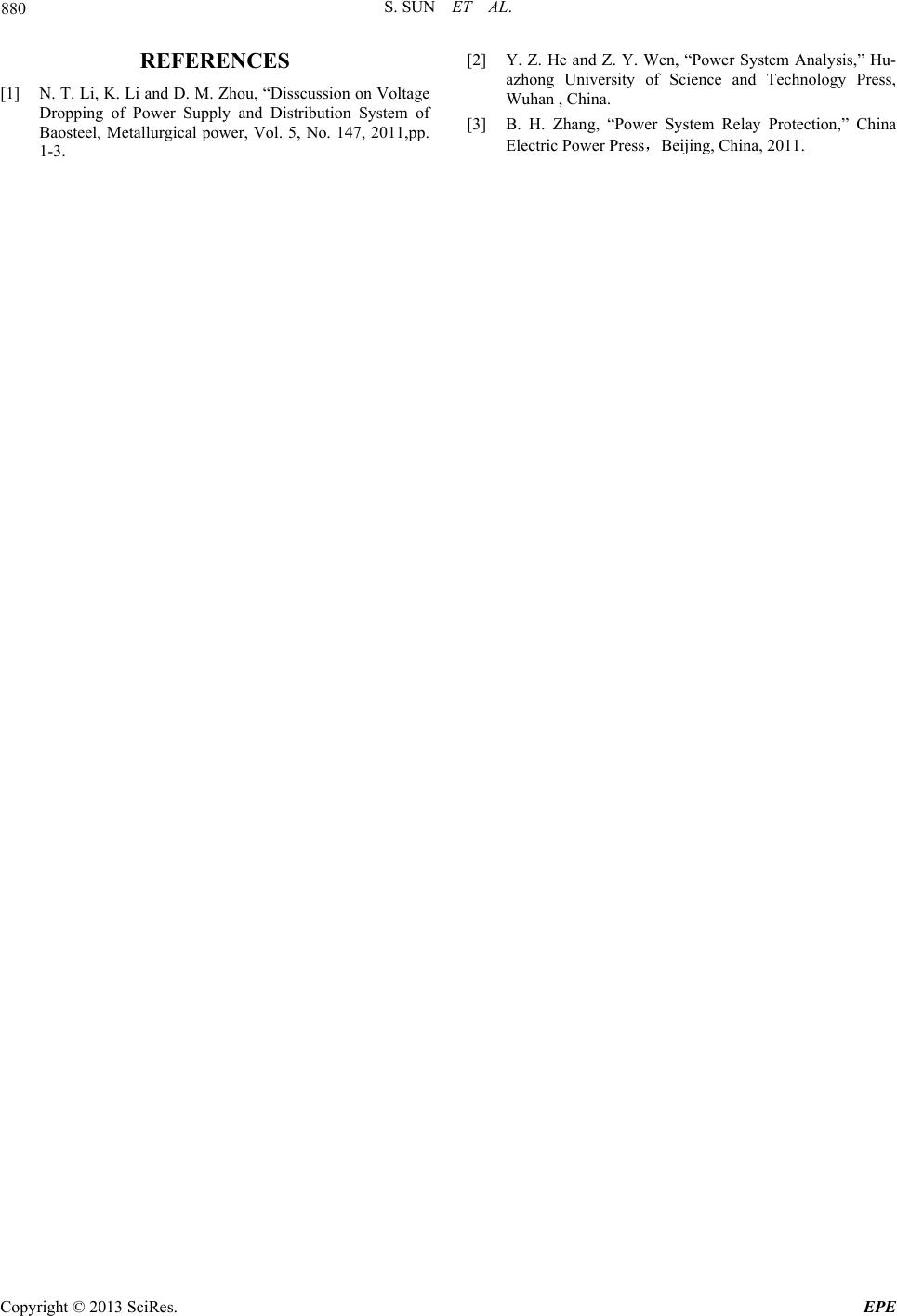 S. SUN ET AL. Copyright © 2013 SciRes. EPE 880 REFERENCES [1] N. T. Li, K. Li and D. M. Zhou, “Disscussion on Voltage Dropping of Power Supply and Distribution System of Baosteel, Metallurgical power, Vol. 5, No. 147, 2011,pp. 1-3. [2] Y. Z. He and Z. Y. Wen, “Power System Analysis,” Hu- azhong University of Science and Technology Press, Wuhan , China. [3] B. H. Zhang, “Power System Relay Protection,” China Electric Power Press,Beijing, China, 2011. |