Paper Menu >>
Journal Menu >>
 Energy and Power Engineering, 2013, 5, 873-876 doi:10.4236/epe.2013.54B167 Published Online July 2013 (http://www.scirp.org/journal/epe) The Research of Voltage Sag and Power Frequency Overvoltage on 110kV Resistance Grounding System Guo Zeng1, Guangliang Feng1, Yanping Lv2, Shan Sun2 1Huangshi Power Supply Company, Huangshi, China 2School of Electrical Engineering, Wuhan University, Wuhan, China Email: sun07126111@163.com Received January, 2013 ABSTRACT This paper researches the voltage transfer characteristics when one-phase ground fault occurred in the resistance grounding system, by using the theory of the asymmetric variable characteristics and the sequence network analysis of the -11 transformer, and concludes the scope of voltage sag and swell and the degree of power frequency overvoltage and their influencing factors in the 110 kV resistance grounding system. Accordingly this paper puts forward the resis- tance choosing principle: the resistance grounding coefficient must be equal to or greater than 10. So it can not only wipe out the voltage sag and voltage swell but also make sure the overvoltage is limited to electrical equipment allow- ing range. The method mentioned above is verified by simulation results of a 110 kV power system in ATP. Keywords: Neutral Grounding System by Resistance; One-phase Grounding Fault; Power Frequency Overvoltage 1. Introduction In China, Most of 110 kV distribution grid use neutral solid ground[1], in this neutral grounding mode, single- phase fault current is very large, sometimes even more than the three-phase fault current. And the single-phase fault will cause a serious voltage sag in the load side which can not satisfy the sensitive users’ requirements for high power quality.Therefore terminal substation of 110 kV side using neutral solid grounding method has been difficult to meet the sensitivity to the requirements of the quality of the electric power load. According to this problem, this paper puts forward the 110 kV neutral grounding system by resistance, and re- searches the relationship between the neutral grounding resistance and the voltage sag degree, power frequency overvoltage level, and tries to make the terminal substa- tion of 110 kV neutral grounding by resistance. After this change, the 110 kV side can eliminate the voltage sag and limit the voltage dip rising and also can ensure the power frequency overvoltage degree not more than the existing 110 kV electrical equipment in the insulation level when one-phase ground fault happened. 2. Voltage Sag and Voltage Swell and Their Trans Ferred by Transformer Voltage sag (also called the voltage drop) is transient electric energy quality problems. It is point to the voltage root-mean-square value to suddenly down or rise in a short time, the typical duration is 0.5 - 30 cycles. IEEE standard defined as: in the power supply system, a cer- tain point’s power frequency voltage RMS suddenly dropped to 10% - 90% of the rating called voltage sag [2]. And these phenomena are returned to normal after the short duration of the next 10 ms – 1 min. 3. The Voltage Sag and Swell in the Resistance Grounding System If the transformer high voltage side happened the A phase grounding fault, the line voltage relationship be- tween high and low voltage side of Y/△ -11 transformer can described by the following formula (1): 110 101 1 3101 ab AB bc BC ca CA UU UU k UU (1) Where, k is the transformation ration. In 110 kV resistance grounding system occurring gold attribute ground fault for a phase, we can deduce 110 kV phase voltages per-unit expression after the fault occur- ring [3]. Copyright © 2013 SciRes. EPE 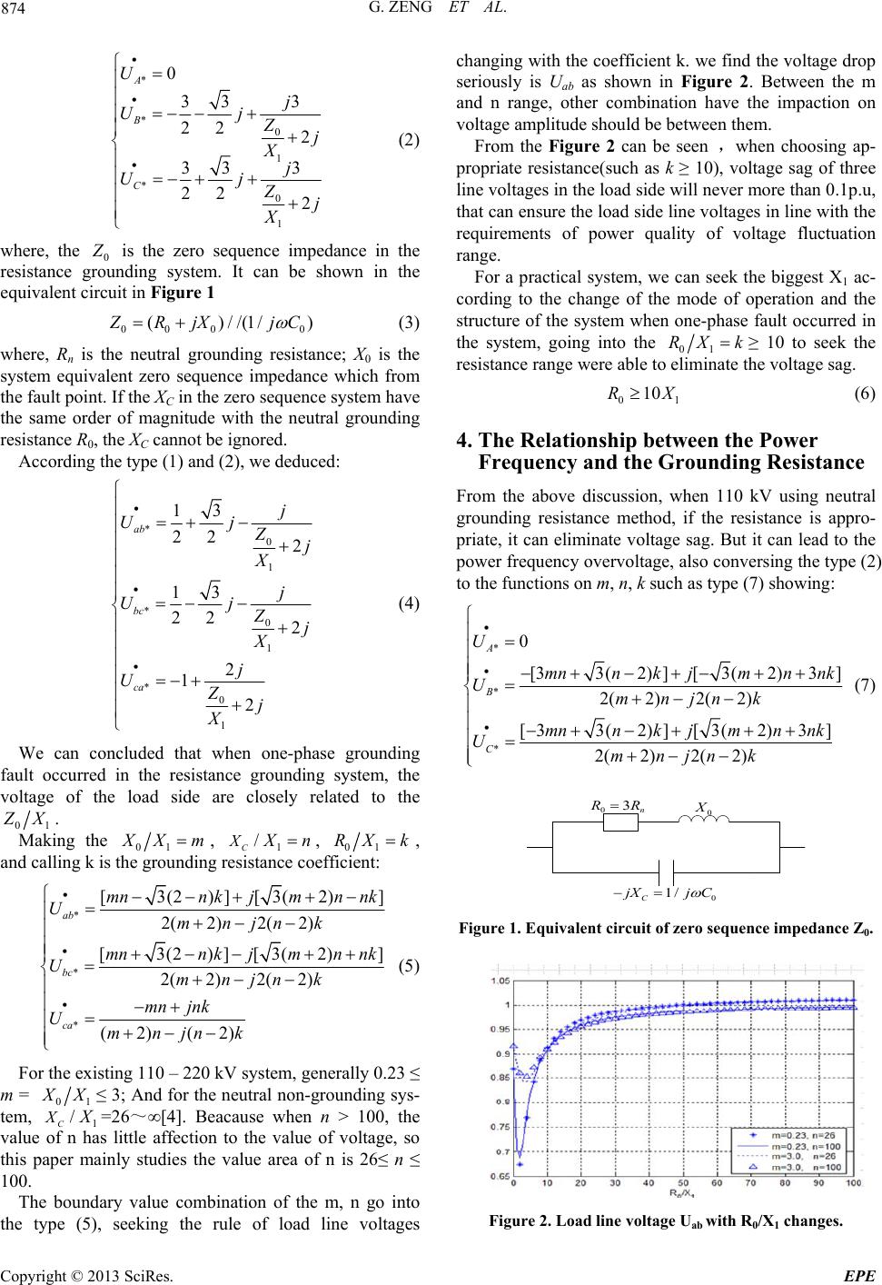 G. ZENG ET AL. 874 * * 0 1 * 0 1 0 33 3 22 2 33 3 22 2 A B C U j Uj Zj Xj Uj Zj X (2) where, the 0 Z is the zero sequence impedance in the resistance grounding system. It can be shown in the equivalent circuit in Figure 1 00 00 ()//(1/) Z RjX jC (3) where, Rn is the neutral grounding resistance; X0 is the system equivalent zero sequence impedance which from the fault point. If the XC in the zero sequence system have the same order of magnitude with the neutral grounding resistance R0, the XC cannot be ignored. According the type (1) and (2), we deduced: * 0 1 * 0 1 * 0 1 13 22 2 13 22 2 2 1 2 ab bc ca j Uj Zj X j Uj Zj X j UZj X (4) We can concluded that when one-phase grounding fault occurred in the resistance grounding system, the voltage of the load side are closely related to the 01 Z X. Making the 01 X Xm, 1 / C X X n, 01 RX k , and calling k is the grounding resistance coefficient: * * * [3(2)][3(2) 2(2)2( 2) [3(2)][3(2) 2(2)2( 2) (2) (2) ab bc ca mnn kjmnnk Umnjnk mnn kjmnnk Umnjnk mn jnk Umnjnk ] ] (5) For the existing 110 – 220 kV system, generally 0.23 ≤ m = 01 X X≤ 3; And for the neutral non-grounding sys- tem, 1 / C X X =26~∞[4]. Beacause when n > 100, the value of n has little affection to the value of voltage, so this paper mainly studies the value area of n is 26≤ n ≤ 100. The boundary value combination of the m, n go into the type (5), seeking the rule of load line voltages changing with the coefficient k. we find the voltage drop seriously is Uab as shown in Figure 2. Between the m and n range, other combination have the impaction on voltage amplitude should be between them. From the Figure 2 can be seen ,when choosing ap- propriate resistance(such as k ≥ 10), voltage sag of three line voltages in the load side will never more than 0.1p.u, that can ensure the load side line voltages in line with the requirements of power quality of voltage fluctuation range. For a practical system, we can seek the biggest X1 ac- cording to the change of the mode of operation and the structure of the system when one-phase fault occurred in the system, going into the 01 RX k≥ 10 to seek the resistance range were able to eliminate the voltage sag. 0 10R1 X (6) 4. The Relationship between the Power Frequency and the Grounding Resistance From the above discussion, when 110 kV using neutral grounding resistance method, if the resistance is appro- priate, it can eliminate voltage sag. But it can lead to the power frequency overvoltage, also conversing the type (2) to the functions on m, n, k such as type (7) showing: * * * 0 [33(2)][3(2)3] 2(2)2( 2) [ 33(2) ][3(2)3] 2(2)2( 2) A B C U mnnkjmnnk Umnjnk mnnkjmnnk Umnjnk (7) 0 X 0 3 n R R 0 1/ C j XjC Figure 1. Equivalent circuit of zero sequence impedance Z0. Figure 2. Load line voltage Uab with R0/X1 changes. Copyright © 2013 SciRes. EPE 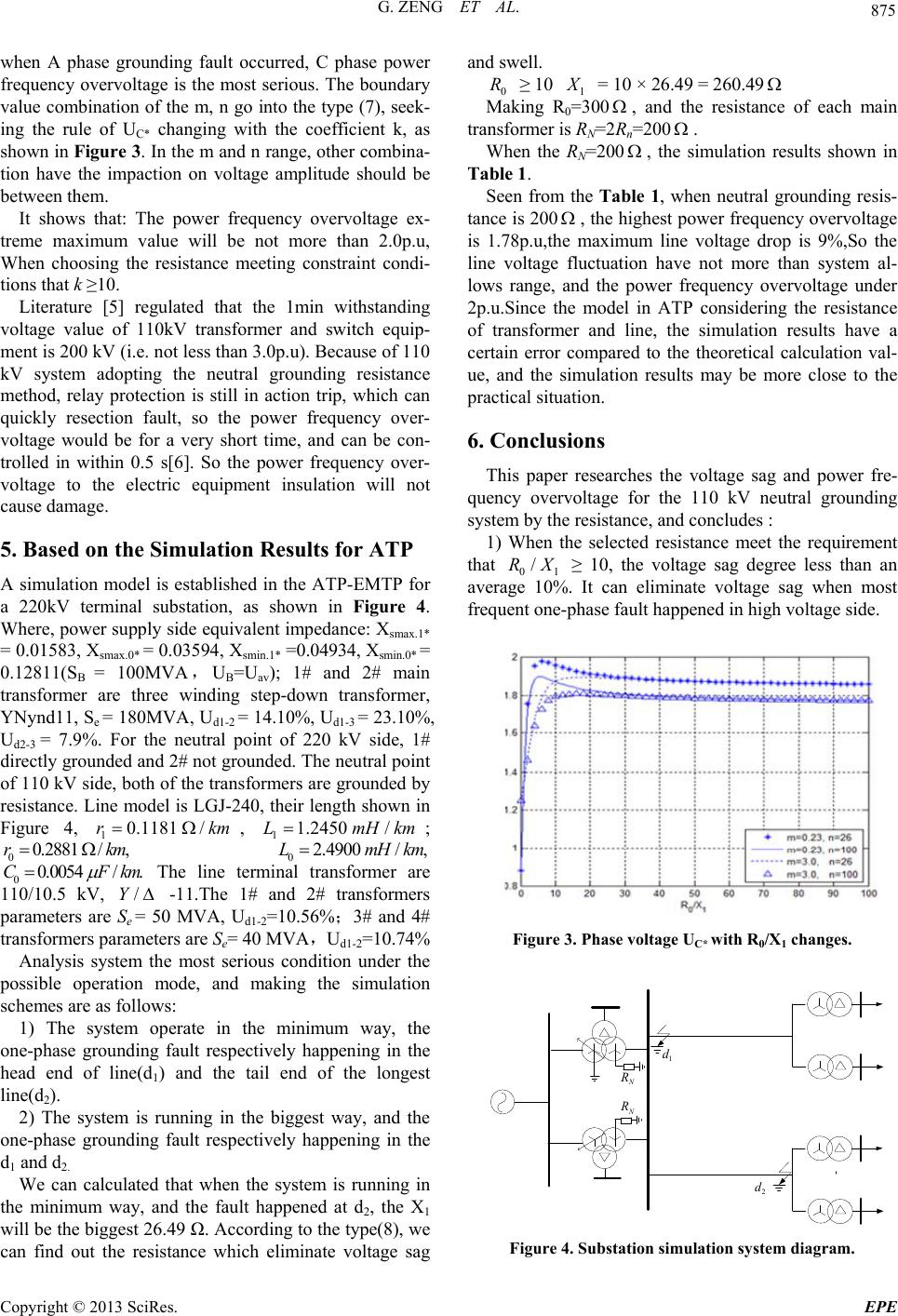 G. ZENG ET AL. 875 when A phase grounding fault occurred, C phase power frequency overvoltage is the most serious. The boundary value combination of the m, n go into the type (7), seek- ing the rule of UC* changing with the coefficient k, as shown in Figure 3. In the m and n range, other combina- tion have the impaction on voltage amplitude should be between them. It shows that: The power frequency overvoltage ex- treme maximum value will be not more than 2.0p.u, When choosing the resistance meeting constraint condi- tions that k ≥10. Literature [5] regulated that the 1min withstanding voltage value of 110kV transformer and switch equip- ment is 200 kV (i.e. not less than 3.0p.u). Because of 110 kV system adopting the neutral grounding resistance method, relay protection is still in action trip, which can quickly resection fault, so the power frequency over- voltage would be for a very short time, and can be con- trolled in within 0.5 s[6]. So the power frequency over- voltage to the electric equipment insulation will not cause damage. 5. Based on the Simulation Results for ATP A simulation model is established in the ATP-EMTP for a 220kV terminal substation, as shown in Figure 4. Where, power supply side equivalent impedance: Xsmax.1* = 0.01583, Xsmax.0* = 0.03594, Xsmin.1* =0.04934, Xsmin.0* = 0.12811(S B = 100MVA,UB=Uav); 1# and 2# main transformer are three winding step-down transformer, YNynd11, Se = 180MVA, Ud1-2 = 14.10%, Ud1-3 = 23.10%, Ud2-3 = 7.9%. For the neutral point of 220 kV side, 1# directly grounded and 2# not grounded. The neutral point of 110 kV side, both of the transformers are grounded by resistance. Line model is LGJ-240, their length shown in Figure 4, , ; 0 0 10.1181 /rk /,rkm 4 /.Fkm m 11.2450 /LmH 2.4900 /LmHkm km 00.2881 0.005C, The line terminal transformer are 110/10.5 kV, -11.The 1# and 2# transformers parameters are Se = 50 MVA, Ud1-2=10.56%;3# and 4# transformers parameters are Se= 40 MVA,Ud1-2=10.74% /Y Analysis system the most serious condition under the possible operation mode, and making the simulation schemes are as follows: 1) The system operate in the minimum way, the one-phase grounding fault respectively happening in the head end of line(d1) and the tail end of the longest line(d2). 2) The system is running in the biggest way, and the one-phase grounding fault respectively happening in the d1 and d2. We can calculated that when the system is running in the minimum way, and the fault happened at d2, the X1 will be the biggest 26.49 Ω. According to the type(8), we can find out the resistance which eliminate voltage sag and swell. 0 1 R ≥ 10 X = 10 × 26.49 = 260.49 Making R0=300 , and the resistance of each main transformer is RN=2Rn=200 . When the RN=200 , the simulation results shown in Table 1. Seen from the Table 1, when neutral grounding resis- tance is 200 , the highest power frequency overvoltage is 1.78p.u,the maximum line voltage drop is 9%,So the line voltage fluctuation have not more than system al- lows range, and the power frequency overvoltage under 2p.u.Since the model in ATP considering the resistance of transformer and line, the simulation results have a certain error compared to the theoretical calculation val- ue, and the simulation results may be more close to the practical situation. 6. Conclusions This paper researches the voltage sag and power fre- quency overvoltage for the 110 kV neutral grounding system by the resistance, and concludes : 1) When the selected resistance meet the requirement that 01 ≥ 10, the voltage sag degree less than an average 10%. It can eliminate voltage sag when most frequent one-phase fault happened in high voltage side. /RX Figure 3. Phase voltage UC* with R0/X1 changes. 1 d 2 d N R N R Figure 4. Substation simulation syste m diagr am. Copyright © 2013 SciRes. EPE  G. ZENG ET AL. Copyright © 2013 SciRes. EPE 876 Table 1. Simulation results. 110 kV bus voltage 1#transformer Y side phase voltage/△ side line voltage 3#transformer Y side phase voltage/△ side line voltage Simula- tion scheme Running status B U* C U* B U*C U*ab U*bc U*ca U* B U*C U* ab U* bc U*ca U* normal 1.0 1.0 0.99 0.99 1.0 1.0 1.0 0.96 0.96 0.99 0.99 0.99 (1) 1A d 1.64 1.78 1.64 1.76 0.96 1.04 0.99 1.63 1.73 0.94 1.02 0.98 schenme 1 (1) 2A d 1.37 1.76 1.36 1.75 0.96 1.03 0.97 1.47 1.65 0.91 1.02 0.91 normal 1.0 1.0 0.99 0.99 1.0 1.0 1.0 0.96 0.96 0.99 0.99 0.99 (1) 1A d 1.67 1.77 1.67 1.75 0.98 1.03 1.0 1.66 1.72 0.96 1.01 0.98 scheme 2 (1) 2A d 1.40 1.77 1.40 1.75 0.98 1.02 0.98 1.50 1.66 0.93 1.01 0.93 [3] D. Tao and X. N. Xiao, “Voltage Sags Types under Dif- ferent Grouding Modes of Neutral and Their Propagation: partⅡ, Transactions of China Electrotechnical Society, Vol. 22, No. 10, 2007,pp. 156-159. 2) The power frequency overvoltage will increase in the neutral grounding resistance system, but the over- voltage will be not more than 2.0p.u.Since the relay pro- tection can fast action to react the fault, so it will be not harmful to the electrical equipment. [4] G. R. Xie, “Power System Overvoltage,” Wuhan Water Electrical Institute Press, China, 1985. [5] The People’s Republic of Electrical Power Industry. Overvoltage Protection and Insulation Coordination for AC Electrical Installations, Beijing, China: China Electric Power Press, 2010. REFERENCES [1] Y. Li, Y. P. Duan, J. Qiu, et al., Voltage Sag Analysis and Fault Position Sag Coefficient Calculation, High Voltage Engineering, Vol. 32, No. 7, 2006,pp. 113-115. [6] Z. Y. Xu, “Digital Protection for Power Transformer and Medial-low Voltage Electric Power Net,” China Water- Power Press, Beijing, China, 2004. [2] IEEE Recommended Practice for Evaluating Electric Power System Compatibility with Electronic Process Equipment[S]. IEEE Standard,1998, pp. 1346-1998. |