Paper Menu >>
Journal Menu >>
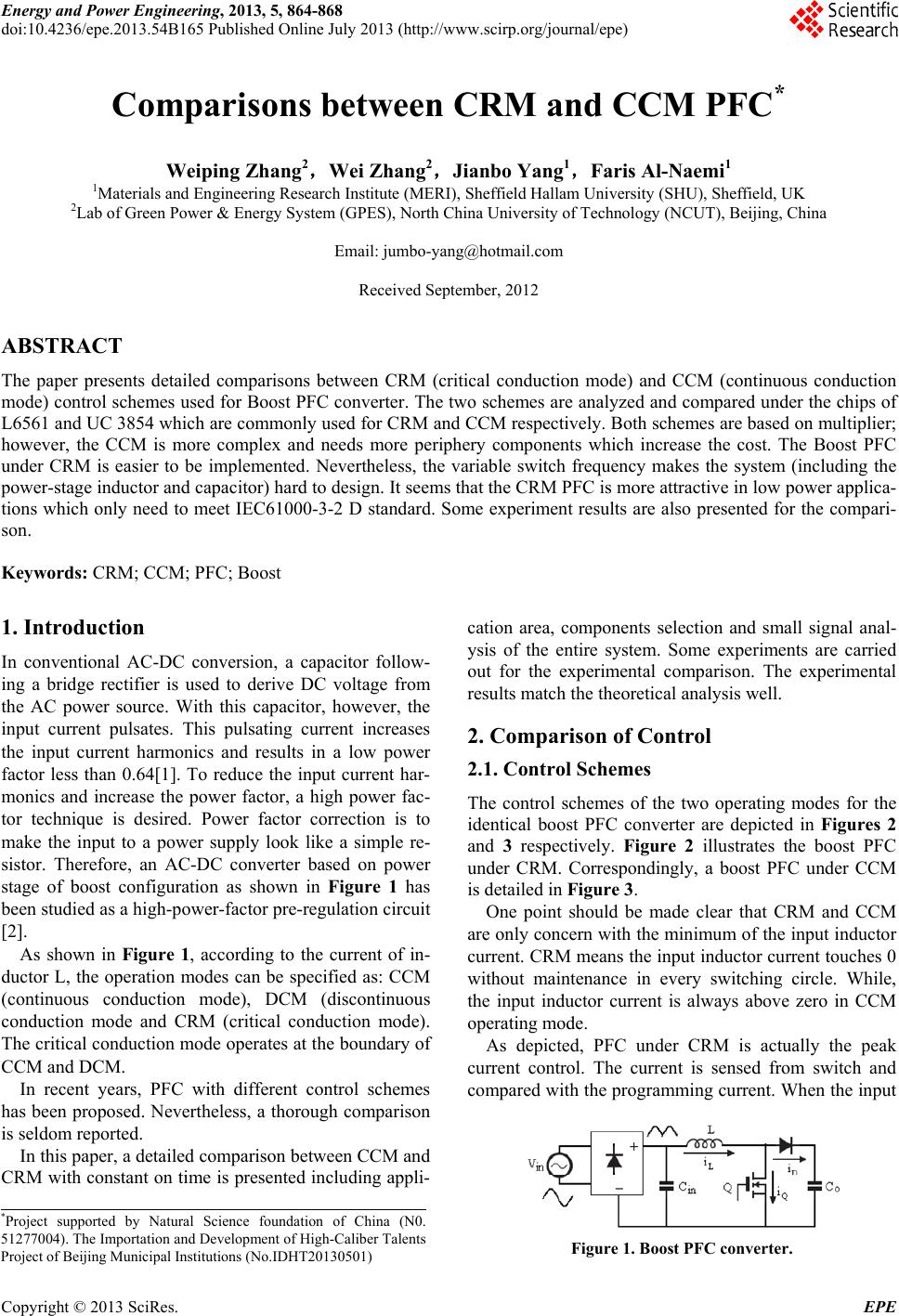 Energy and Power Engineering, 2013, 5, 864-868 doi:10.4236/epe.2013.54B165 Published Online July 2013 (http://www.scirp.org/journal/epe) Comparisons between CRM and CCM PFC* Weiping Zhang2,Wei Zhang2,Jianbo Yang1,Faris Al-Naemi1 1Materials and Engineering Research Institute (MERI), Sheffield Hallam University (SHU), Sheffield, UK 2Lab of Green Power & Energy System (GPES), North China University of Technology (NCUT), Beijing, China Email: jumbo-yang@hotmail.com Received September, 2012 ABSTRACT The paper presents detailed comparisons between CRM (critical conduction mode) and CCM (continuous conduction mode) control schemes used for Boost PFC converter. The two schemes are analyzed and compared under the chips of L6561 and UC 3854 which are commonly used for CRM and CCM respectiv ely. Both schemes are based on multiplier; however, the CCM is more complex and needs more periphery components which increase the cost. The Boost PFC under CRM is easier to be implemented. Nevertheless, the variable switch frequency makes the system (including the power-stage inductor and capacitor) hard to design. It seems that the CRM PFC is more attractive in low power applica- tions which only need to meet IEC61000-3-2 D standard. Some experiment results are also presented for the compari- son. Keywords: CRM; CCM; PFC; Boost 1. Introduction In conventional AC-DC conversion, a capacitor follow- ing a bridge rectifier is used to derive DC voltage from the AC power source. With this capacitor, however, the input current pulsates. This pulsating current increases the input current harmonics and results in a low power factor less than 0.64[1]. To reduce the input current har- monics and increase the power factor, a high power fac- tor technique is desired. Power factor correction is to make the input to a power supply look like a simple re- sistor. Therefore, an AC-DC converter based on power stage of boost configuration as shown in Figure 1 has been studied as a high-power-factor pre-regulation circuit [2]. As shown in Figure 1, according to the current of in- ductor L, the operation modes can be specified as: CCM (continuous conduction mode), DCM (discontinuous conduction mode and CRM (critical conduction mode). The critical conduction mode operates at the boundary of CCM and DCM. In recent years, PFC with different control schemes has been pro posed. Nevertheless, a thorough comparison is seldom reported. In this paper, a detailed comparison b etween CCM and CRM with constant on time is presented includ ing appli- cation area, components selection and small signal anal- ysis of the entire system. Some experiments are carried out for the experimental comparison. The experimental results match the theoretical analysis well. 2. Comparison of Control 2.1. Control Schemes The control schemes of the two operating modes for the identical boost PFC converter are depicted in Figures 2 and 3 respectively. Figure 2 illustrates the boost PFC under CRM. Correspondingly, a boost PFC under CCM is detailed in Figure 3. One point should be made clear that CRM and CCM are only concern with th e minimum of the input inductor current. CRM means the input inductor current touches 0 without maintenance in every switching circle. While, the input inductor current is always above zero in CCM operating mode. As depicted, PFC under CRM is actually the peak current control. The current is sensed from switch and compared with the programming current. When the input *Project supported by Natural Science foundation of China (N0. 51277004). The Importation and Development of High-Caliber Talents Project of Beijing Municipal Institutions (No.IDHT20130501) Figure 1. Boost PF C converter. Copyright © 2013 SciRes. EPE 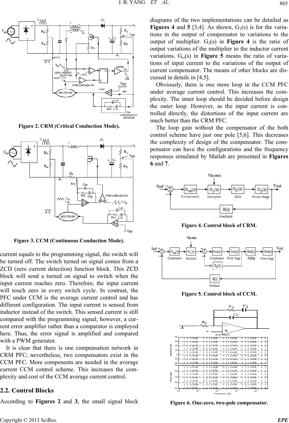 J. B. YANG ET AL. 865 Figure 2. CRM (Critical Conduction Mode). Figure 3. CCM (Continuous Conduction M o de ). current equals to the programming signal, the switch will be turned off. The switch turned on signal comes from a ZCD (zero current detection) function block. This ZCD block will send a turned on signal to switch when the input current reaches zero. Therefore, the input current will touch zero in every switch cycle. In contrast, the PFC under CCM is the average current control and has different configuration. The input current is sensed from inductor instead of the switch. Th is sensed current is still compared with the programming signal; however, a cur- rent error amplifier rather than a comparator is employed here. Thus, the error signal is amplified and compared with a PWM generator. It is clear that there is one compensation network in CRM PFC; nevertheless, two compensators exist in the CCM PFC. More components are needed in the average current CCM control scheme. This increases the com- plexity and cost of the CCM average current control. 2.2. Control Blocks According to Figures 2 and 3, the small signal block diagrams of the two implementations can be detailed as Figures 4 and 5 [3,4]. As shown, G1(s) is for the varia- tions in the output of compensator to variations to the output of multiplier. G2(s) in Figure 4 is the ratio of output variations of the multiplier to the inductor current variations. Gci(s) in Figure 5 means the ratio of varia- tions of input current to the variations of the output of current compensator. The means of other blocks are dis- cussed in details in [4,5]. Obviously, there is one more loop in the CCM PFC under average current control. This increases the com- plexity. The inner loop should be decided before design the outer loop. However, as the input current is con- trolled directly, the distortions of the input current are much better than the CRM PFC. The loop gain without the compensator of the both control scheme have just one pole [5,6]. This decreases the complexity of design of the compensator. The com- pensator can have the configurations and the frequency responses simulated by Matlab are presented in Figures 6 and 7. Figure 4. Control block of CRM. Figure 5. Control block of CCM. -40 -20 0 20 40 60 80 Magnitude (dB) 10 0 10 1 10 2 10 3 10 4 -90 -80 -70 -60 -50 Phase (deg) Bode Diagram Frequenc y (HZ) Figure 6. One-zero, two-pole compensator. Copyright © 2013 SciRes. EPE 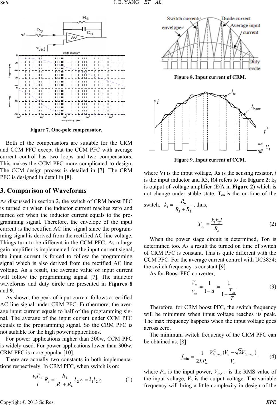 J. B. YANG ET AL. 866 -80 -60 -40 -20 0 M agnitude (dB) 10 0 10 1 10 2 10 3 10 4 -90 -45 0 Phase (deg) Bode Diagram Frequency (HZ) Figure 7. One-pole compensator. Both of the compensators are suitable for the CRM and CCM PFC except that the CCM PFC with average current control has two loops and two compensators. This makes the CCM PFC more complicated to design. The CCM design process is detailed in [7]. The CRM PFC is designed in detail in [8]. 3. Comparison of Waveforms As discussed in section 2, the switch of CRM boost PFC is turned on when the inductor current reaches zero and turned off when the inductor current equals to the pro- gramming signal. Therefore, the envelope of the input current is the rectified AC line signal since the program- ming signal is derived from the rectified AC line voltage. Things turn to be different in the CCM PFC. As a large gain amplifier is implemented for the input current signal, the input current is forced to follow the programming signal which is also derived from the rectified AC line voltage. As a result, the average value of input current will follow the programming signal [7]. The inductor waveforms and duty circle are presented in Figures 8 and 9. As shown, the peak of input current follows a rectified AC line signal under CRM PFC. Furthermore, the aver- age input current equals to half of the programming sig- nal. The average of the input current under CCM PFC equals to the programming signal. So the CRM PFC is not suitable f or the hig h po wer application s . For power applications higher than 300w, CCM PFC is widely used. For power applications lower than 300w, CRM PFC is more popular [10]. There are actually two constants in both implementa- tions respectively. In CRM PFC, when switch is on: 4212 34 ion s i vT R Rkvk lRR Figure 8. Input current of CRM. Figure 9. Input current of CCM. where Vi is the input voltage, Rs is the sensing resistor, l is the input inductor and R3, R4 refers to the Figure 2; k 2 is output of voltage amplifier (E/A in Figure 2) which is not change under stable state. Ton is the on-time of the switch. 4 134 R kRR , thus, 12 on s kkl TR (2) When the power stage circuit is determined, Ton is determined too. As a result the turned on time of switch of CRM PFC is constant. This is quite different with the CCM PFC. For the average current control with UC3854; the switch frequency is constant [9]. As for B o o s t PFC conver t e r, 11 11 o on in V T vd T (3) Therefore, for CRM boost PFC, the switch frequency will be minimum when input voltage reaches its peak. The max frequency happens when the input voltage goes across zero. The minimum switch frequency of the CRM PFC can be obtaine d as, [8] 2, min (2 1 2 in rmsoin rms in o VV V fLP V , ) (4) where Pin is the input power, Vin,rms is the RMS value of the input voltage, Vo is the output voltage. The variable frequency will bring a little complexity in design of the i kv (1) Copyright © 2013 SciRes. EPE 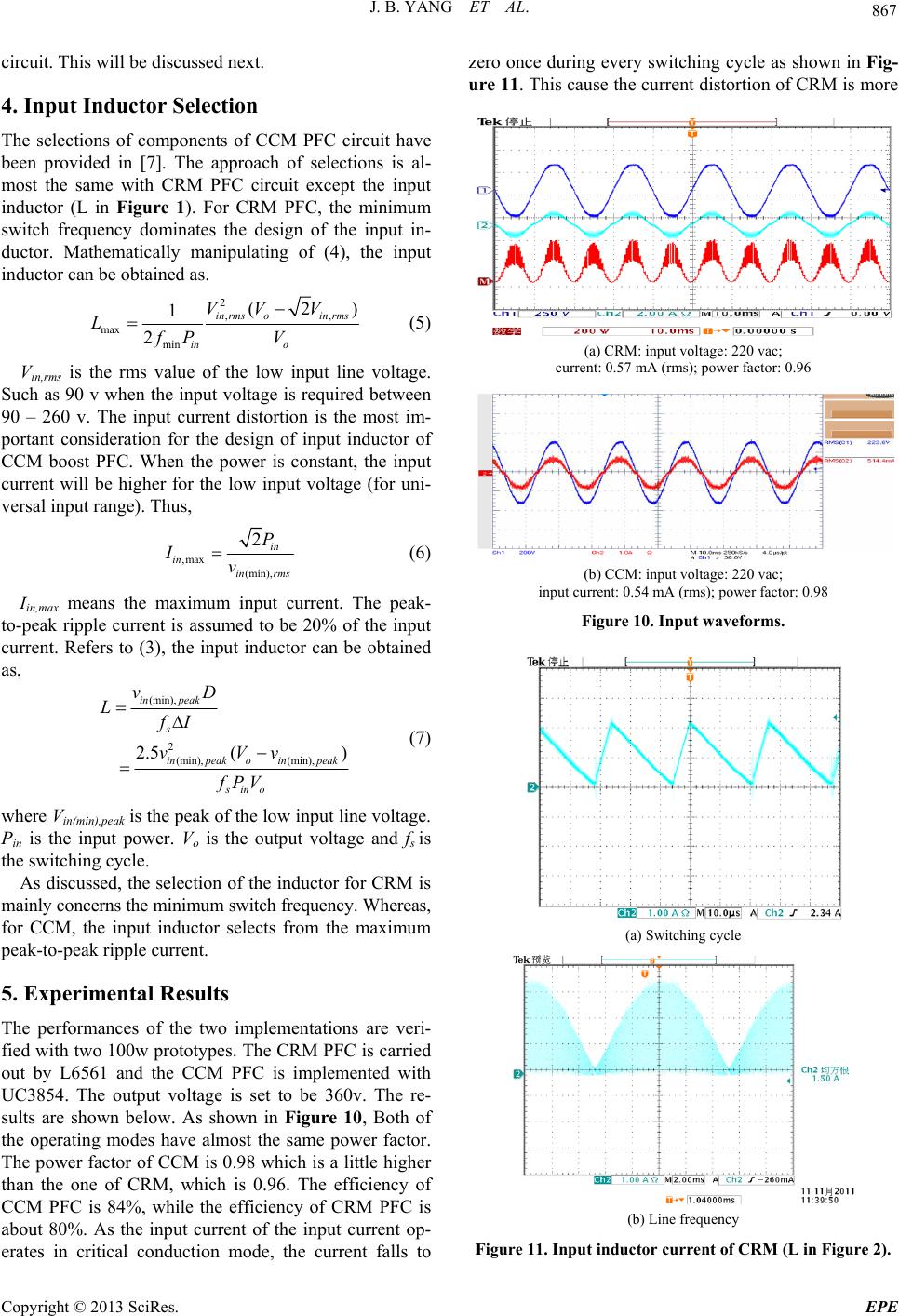 J. B. YANG ET AL. 867 circuit. This will be discussed next. 4. Input Inductor Selection The selections of components of CCM PFC circuit have been provided in [7]. The approach of selections is al- most the same with CRM PFC circuit except the input inductor (L in Figure 1). For CRM PFC, the minimum switch frequency dominates the design of the input in- ductor. Mathematically manipulating of (4), the input inductor can be obtained as. 2, max min (2 1 2 in rmsoin rms in o VV V LfP V , ) (5) Vin,rms is the rms value of the low input line voltage. Such as 90 v when the input voltage is required between 90 – 260 v. The input current distortion is the most im- portant consideration for the design of input inductor of CCM boost PFC. When the power is constant, the input current will be higher for the low input voltage (for uni- versal input range). Thus, ,max (min), 2in in in rms P Iv (6) Iin,max means the maximum input current. The peak- to-peak ripple current is assumed to be 20% of the input current. Refers to (3), the input inductor can be obtained as, (min), 2(min), (min), 2.5 () in peak s in peakoin peak sino vD LfI vVv fPV (7) where Vin(min),peak is the peak of the low input line voltage. Pin is the input power. Vo is the output voltage and fs is the switching cycle. As discussed, the selection of the inductor for CRM is mainly concerns the minimum switch frequency. Whereas, for CCM, the input inductor selects from the maximum peak-to-peak rippl e c urrent. 5. Experimental Results The performances of the two implementations are veri- fied with two 100w proto types. The CRM PFC is carried out by L6561 and the CCM PFC is implemented with UC3854. The output voltage is set to be 360v. The re- sults are shown below. As shown in Figure 10, Both of the operating modes have almost the same power factor. The power factor of CCM is 0.98 which is a little higher than the one of CRM, which is 0.96. The efficiency of CCM PFC is 84%, while the efficiency of CRM PFC is about 80%. As the input current of the input current op- erates in critical conduction mode, the current falls to zero once during every switching cycle as shown in Fig- ure 11. This cause the current distortion of CRM is more (a) CRM: input vo ltage: 220 vac; current: 0.57 m A (rms); power factor: 0.96 (b) CCM: input voltage: 220 vac; input current: 0.54 mA (rms); power factor: 0.98 Figure 10. Input waveforms. (a) Switching cycle (b) Line frequen c y Figure 11. Input inductor current of CRM (L in Figure 2). Copyright © 2013 SciRes. EPE 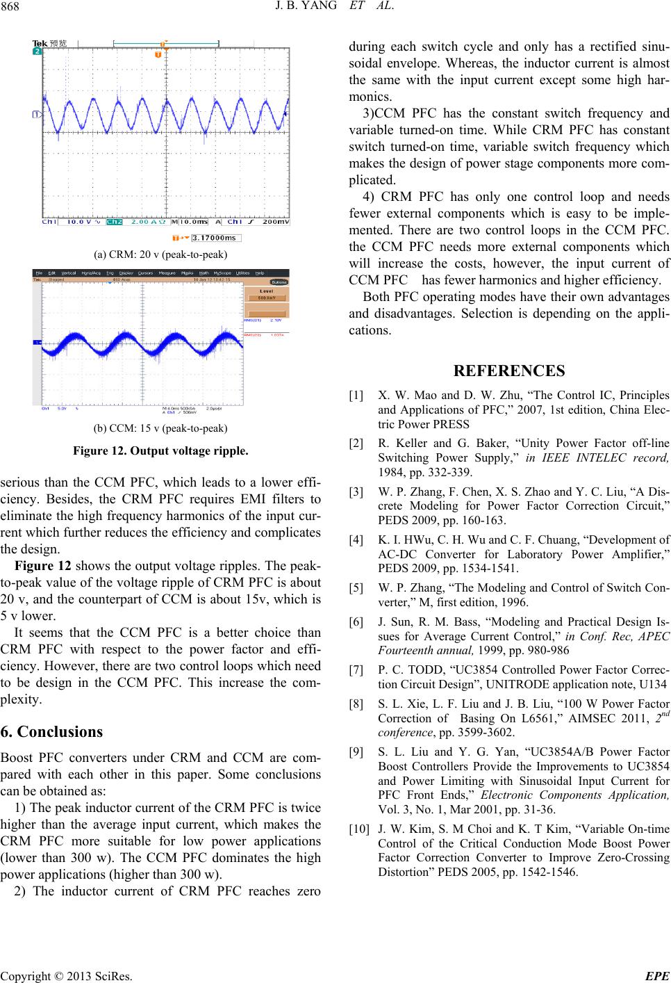 J. B. YANG ET AL. Copyright © 2013 SciRes. EPE 868 (a) CRM: 20 v (peak-to-peak) (b) CCM: 15 v (peak-to-peak) Figure 12. Output voltage ripple. serious than the CCM PFC, which leads to a lower effi- ciency. Besides, the CRM PFC requires EMI filters to eliminate the high frequency harmonics of the input cur- rent which further reduces the efficiency and complicates the design. Figure 12 shows the output voltage ripples. The peak- to-peak value of the vo ltage ripple of CRM PFC is about 20 v, and the counterpart of CCM is about 15v, which is 5 v lower. It seems that the CCM PFC is a better choice than CRM PFC with respect to the power factor and effi- ciency. However, there are two control loops which need to be design in the CCM PFC. This increase the com- plexity. 6. Conclusions Boost PFC converters under CRM and CCM are com- pared with each other in this paper. Some conclusions can be obtained as: 1) The peak inductor current of the CRM PFC is twice higher than the average input current, which makes the CRM PFC more suitable for low power applications (lower than 300 w). The CCM PFC dominates the high power applications (higher than 300 w). 2) The inductor current of CRM PFC reaches zero during each switch cycle and only has a rectified sinu- soidal envelope. Whereas, the inductor current is almost the same with the input current except some high har- monics. 3)CCM PFC has the constant switch frequency and variable turned-on time. While CRM PFC has constant switch turned-on time, variable switch frequency which makes the design of power stage components more com- plicated. 4) CRM PFC has only one control loop and needs fewer external components which is easy to be imple- mented. There are two control loops in the CCM PFC. the CCM PFC needs more external components which will increase the costs, however, the input current of CCM PFC has fewer harmonics and higher efficiency. Both PFC operating modes have their own advantages and disadvantages. Selection is depending on the appli- cations. REFERENCES [1] X. W. Mao and D. W. Zhu, “The Control IC, Principles and Applications of PFC,” 2007, 1st edition, China Elec- tric Power PRESS [2] R. Keller and G. Baker, “Unity Power Factor off-line Switching Power Supply,” in IEEE INTELEC record, 1984, pp. 332-339. [3] W. P. Zhang, F. Chen, X. S. Zhao and Y. C. Liu, “A Dis- crete Modeling for Power Factor Correction Circuit,” PEDS 2009, pp. 160-163. [4] K. I. HWu, C. H. Wu and C. F. Chuang, “Development of AC-DC Converter for Laboratory Power Amplifier,” PEDS 2009, pp. 1534-1541. [5] W. P. Zhang, “The Modeling and Control of Switch Con- verter,” M, first edition, 1996. [6] J. Sun, R. M. Bass, “Modeling and Practical Design Is- sues for Average Current Control,” in Conf. Rec, APEC Fourteenth annual, 1999, pp. 980-986 [7] P. C. TODD, “UC3854 Controlled Power Factor Correc- tion Circuit Design”, UNITRODE application note, U134 [8] S. L. Xie, L. F. Liu and J. B. Liu, “100 W Power Factor Correction of Basing On L6561,” AIMSEC 2011, 2nd conference, pp. 3599-3602. [9] S. L. Liu and Y. G. Yan, “UC3854A/B Power Factor Boost Controllers Provide the Improvements to UC3854 and Power Limiting with Sinusoidal Input Current for PFC Front Ends,” Electronic Components Application, Vol. 3, No. 1, Mar 2001, pp. 31-36. [10] J. W. Kim, S. M Choi and K. T Kim, “Variable On-time Control of the Critical Conduction Mode Boost Power Factor Correction Converter to Improve Zero-Crossing Distortion” PEDS 2005, pp. 1542-1546. |