Paper Menu >>
Journal Menu >>
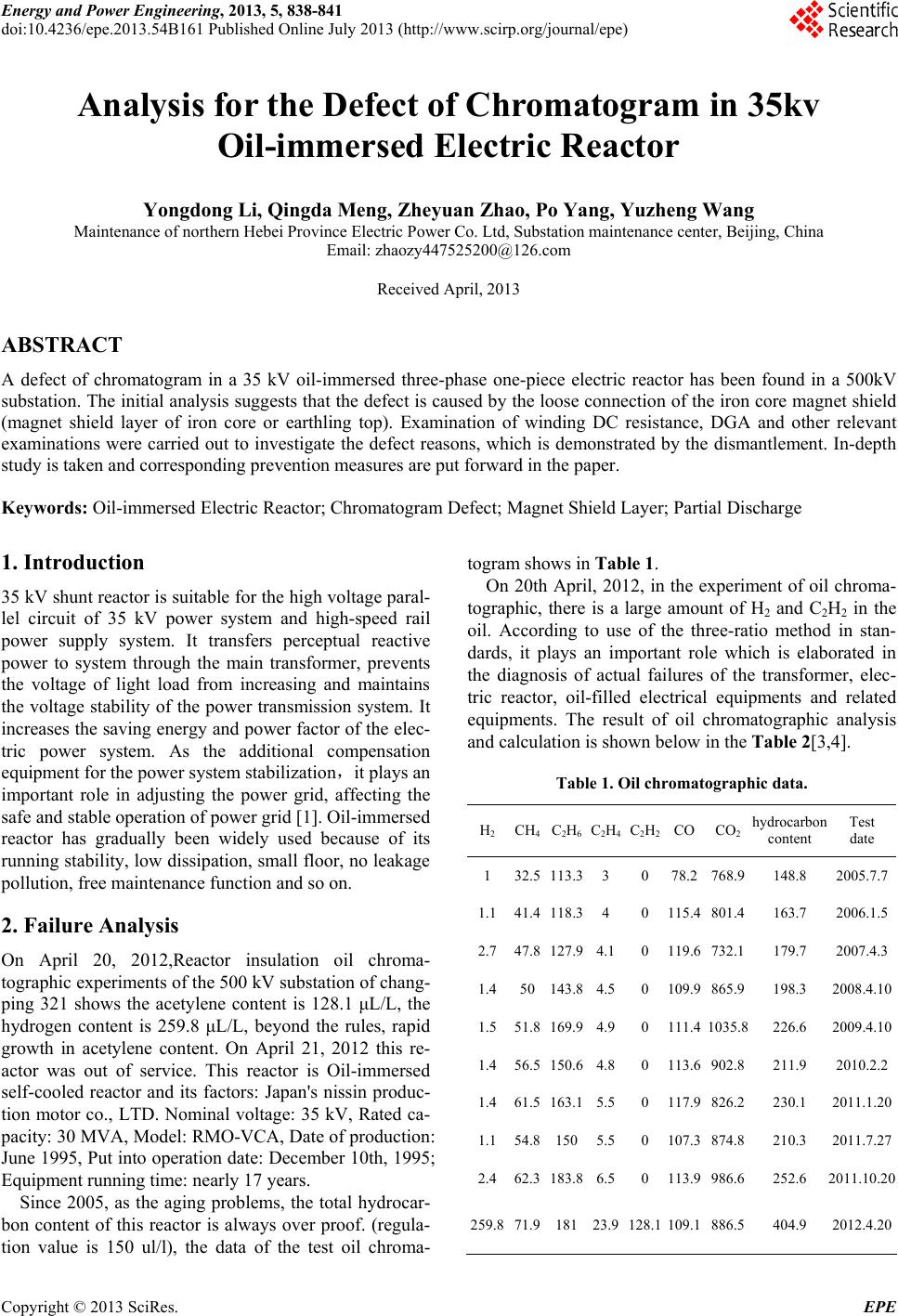 Energy and Power Engineering, 2013, 5, 838-841 doi:10.4236/epe.2013.54B161 Published Online July 2013 (http://www.scirp.org/journal/epe) Analysis for the Defect of Chromatogram in 35kv Oil-immersed Electric Reactor Yongdong Li, Qingda Meng, Zheyuan Zhao, Po Yang, Yuzheng Wang Maintenance of northern Hebei Province Electric Power Co. Ltd, Substation maintenance center, Beijing, China Email: zhaozy447525200@126.com Received April, 2013 ABSTRACT A defect of chromatogram in a 35 kV oil-immersed three-phase one-piece electric reactor has been found in a 500kV substation. The initial analysis suggests that the defect is caused by the loose connection of the iron core magnet shield (magnet shield layer of iron core or earthling top). Examination of winding DC resistance, DGA and other relevant examinations were carried out to investigate the defect reasons, which is demonstrated by the dismantlement. In-depth study is taken and corresponding prevention measures are put forward in the paper. Keywords: Oil-immersed Electric Reactor; Chromatogram Defect; Magnet Shield Layer; Partial Discharge 1. Introduction 35 kV shunt reactor is suitable for the high voltage paral- lel circuit of 35 kV power system and high-speed rail power supply system. It transfers perceptual reactive power to system through the main transformer, prevents the voltage of light load from increasing and maintains the voltage stability of the power transmission system. It increases the saving energy and power factor of the elec- tric power system. As the additional compensation equipment for the power system stabilization,it plays an important role in adjusting the power grid, affecting the safe and stable operation of power grid [1]. Oil-immersed reactor has gradually been widely used because of its running stability, low dissipation, small floor, no leakage pollution, free maintenance function and so on. 2. Failure Analysis On April 20, 2012,Reactor insulation oil chroma- tographic experiments of the 500 kV substation of chang- ping 321 shows the acetylene content is 128.1 μL/L, the hydrogen content is 259.8 μL/L, beyond the rules, rapid growth in acetylene content. On April 21, 2012 this re- actor was out of service. This reactor is Oil-immersed self-cooled reactor and its factors: Japan's nissin produc- tion motor co., LTD. Nominal voltage: 35 kV, Rated ca- pacity: 30 MVA, Model: RMO-VCA, Date of production: June 1995, Put into operation date: December 10th, 1995; Equipment running time: nearly 17 years. Since 2005, as the aging problems, the total hydrocar- bon content of this reactor is always over proof. (regula- tion value is 150 ul/l), the data of the test oil chroma- togram shows in Table 1. On 20th April, 2012, in the experiment of oil chroma- tographic, there is a large amount of H2 and C2H2 in the oil. According to use of the three-ratio method in stan- dards, it plays an important role which is elaborated in the diagnosis of actual failures of the transformer, elec- tric reactor, oil-filled electrical equipments and related equipments. The result of oil chromatographic analysis and calculation is shown below in the Table 2[3,4]. Table 1. Oil chromatographic data. H2CH4C2H6C2H4C2H2CO CO2 hydrocarbon content Test date 1 32.5113.33 0 78.2 768.9 148.8 2005.7.7 1.141.4118.34 0 115.4 801.4 163.7 2006.1.5 2.747.8127.94.10 119.6 732.1 179.7 2007.4.3 1.450143.84.50 109.9 865.9 198.3 2008.4.10 1.551.8169.94.90 111.4 1035.8 226.6 2009.4.10 1.456.5150.64.80 113.6 902.8 211.9 2010.2.2 1.461.5163.15.50 117.9 826.2 230.1 2011.1.20 1.154.8150 5.50 107.3 874.8 210.3 2011.7.27 2.462.3183.86.50 113.9 986.6 252.6 2011.10.20 259.8 71.918123.9128.1109.1 886.5 404.9 2012.4.20 Copyright © 2013 SciRes. EPE 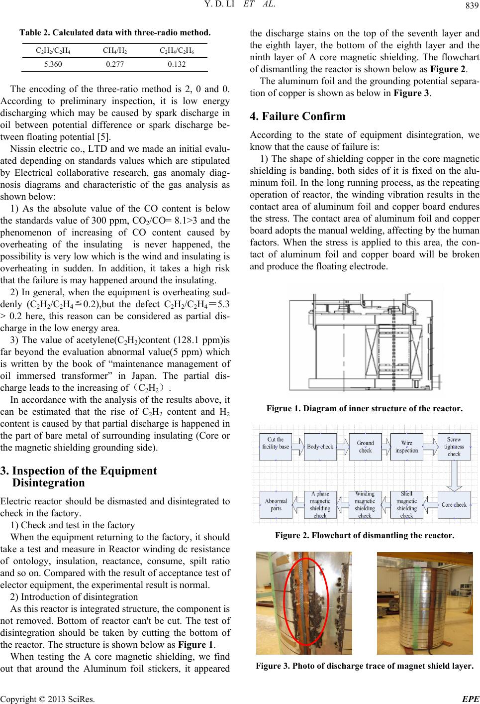 Y. D. LI ET AL. 839 Table 2. Calculated data with three-radio method. C2H2/C2H4 CH4/H2 C 2H4/C2H6 5.360 0.277 0.132 The encoding of the three-ratio method is 2, 0 and 0. According to preliminary inspection, it is low energy discharging which may be caused by spark discharge in oil between potential difference or spark discharge be- tween floating potential [5]. Nissin electric co., LTD and we made an initial evalu- ated depending on standards values which are stipulated by Electrical collaborative research, gas anomaly diag- nosis diagrams and characteristic of the gas analysis as shown below: 1) As the absolute value of the CO content is below the standards value of 300 ppm, CO2/CO= 8.1>3 and the phenomenon of increasing of CO content caused by overheating of the insulating is never happened, the possibility is very low which is the wind and insulating is overheating in sudden. In addition, it takes a high risk that the failure is may happened around the insulating. 2) In general, when the equipment is overheating sud- denly (C2H2/C2H4≦0.2),but the defect C2H2/C2H4=5.3 > 0.2 here, this reason can be considered as partial dis- charge in the low energy area. 3) The value of acetylene(C2H2)content (128.1 ppm)is far beyond the evaluation abnormal value(5 ppm) which is written by the book of “maintenance management of oil immersed transformer” in Japan. The partial dis- charge leads to the increasing of(C2H2). In accordance with the analysis of the results above, it can be estimated that the rise of C2H2 content and H2 content is caused by that partial discharge is happened in the part of bare metal of surrounding insulating (Core or the magnetic shielding grounding side). 3. Inspection of the Equipment Disintegration Electric reactor should be dismasted and disintegrated to check in the factory. 1) Check and test in the factory When the equipment returning to the factory, it should take a test and measure in Reactor winding dc resistance of ontology, insulation, reactance, consume, spilt ratio and so on. Compared with the result of acceptance test of elector equipment, the experimental result is normal. 2) Introduction of disintegration As this reactor is integrated structure, the component is not removed. Bottom of reactor can't be cut. The test of disintegration should be taken by cutting the bottom of the reactor. The structure is shown below as Figure 1. When testing the A core magnetic shielding, we find out that around the Aluminum foil stickers, it appeared the discharge stains on the top of the seventh layer and the eighth layer, the bottom of the eighth layer and the ninth layer of A core magnetic shielding. The flowchart of dismantling the reactor is shown below as Figure 2. The aluminum foil and the grounding potential separa- tion of copper is shown as below in Figure 3. 4. Failure Confirm According to the state of equipment disintegration, we know that the cause of failure is: 1) The shape of shielding copper in the core magnetic shielding is banding, both sides of it is fixed on the alu- minum foil. In the long running process, as the repeating operation of reactor, the winding vibration results in the contact area of aluminum foil and copper board endures the stress. The contact area of aluminum foil and copper board adopts the manual welding, affecting by the human factors. When the stress is applied to this area, the con- tact of aluminum foil and copper board will be broken and produce the floating electrode. Figrue 1. Diagram of inner structure of the reactor. Figure 2. Flowchart of dismantling the reactor. Figure 3. Photo of discharge trace of magnet shield layer. Copyright © 2013 SciRes. EPE 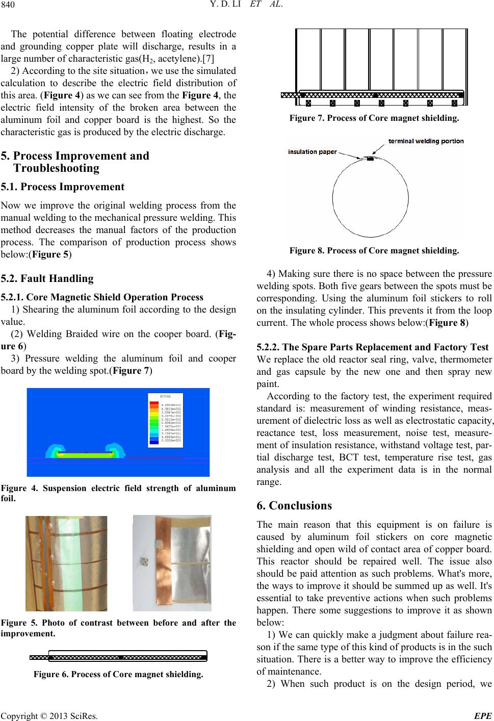 Y. D. LI ET AL. 840 The potential difference between floating electrode and grounding copper plate will discharge, results in a large number of characteristic gas(H2, acetylene).[7] 2) According to the site situation,we use the simulated calculation to describe the electric field distribution of this area. (Figure 4) as we can see from the Figure 4, the electric field intensity of the broken area between the aluminum foil and copper board is the highest. So the characteristic gas is produced by the electric discharge. 5. Process Improvement and Troubleshooting 5.1. Process Improvement Now we improve the original welding process from the manual welding to the mechanical pressure welding. This method decreases the manual factors of the production process. The comparison of production process shows below:(Figure 5) 5.2. Fault Handling 5.2.1. Core Magneti c Sh ield Operation Process 1) Shearing the aluminum foil according to the design value. (2) Welding Braided wire on the cooper board. (Fig- ure 6) 3) Pressure welding the aluminum foil and cooper board by the welding spot.(Figure 7 ) Figure 4. Suspension electric field strength of aluminum foil. Figure 5. Photo of contrast between before and after the improvement. Figure 6. Process of Core magnet shielding. Figure 7. Process of Core magnet shielding. Figure 8. Process of Core magnet shielding. 4) Making sure there is no space between the pressure welding spots. Both five gears between the spots must be corresponding. Using the aluminum foil stickers to roll on the insulating cylinder. This prevents it from the loop current. The whole process shows below:(Figure 8) 5.2.2. The Spare Parts Replacemen t and Factory Test We replace the old reactor seal ring, valve, thermometer and gas capsule by the new one and then spray new paint. According to the factory test, the experiment required standard is: measurement of winding resistance, meas- urement of dielectric loss as well as electrostatic capacity, reactance test, loss measurement, noise test, measure- ment of insulation resistance, withstand voltage test, par- tial discharge test, BCT test, temperature rise test, gas analysis and all the experiment data is in the normal range. 6. Conclusions The main reason that this equipment is on failure is caused by aluminum foil stickers on core magnetic shielding and open wild of contact area of copper board. This reactor should be repaired well. The issue also should be paid attention as such problems. What's more, the ways to improve it should be summed up as well. It's essential to take preventive actions when such problems happen. There some suggestions to improve it as shown below: 1) We can quickly make a judgment about failure rea- son if the same type of this kind of products is in the such situation. There is a better way to improve the efficiency of maintenance. 2) When such product is on the design period, we Copyright © 2013 SciRes. EPE 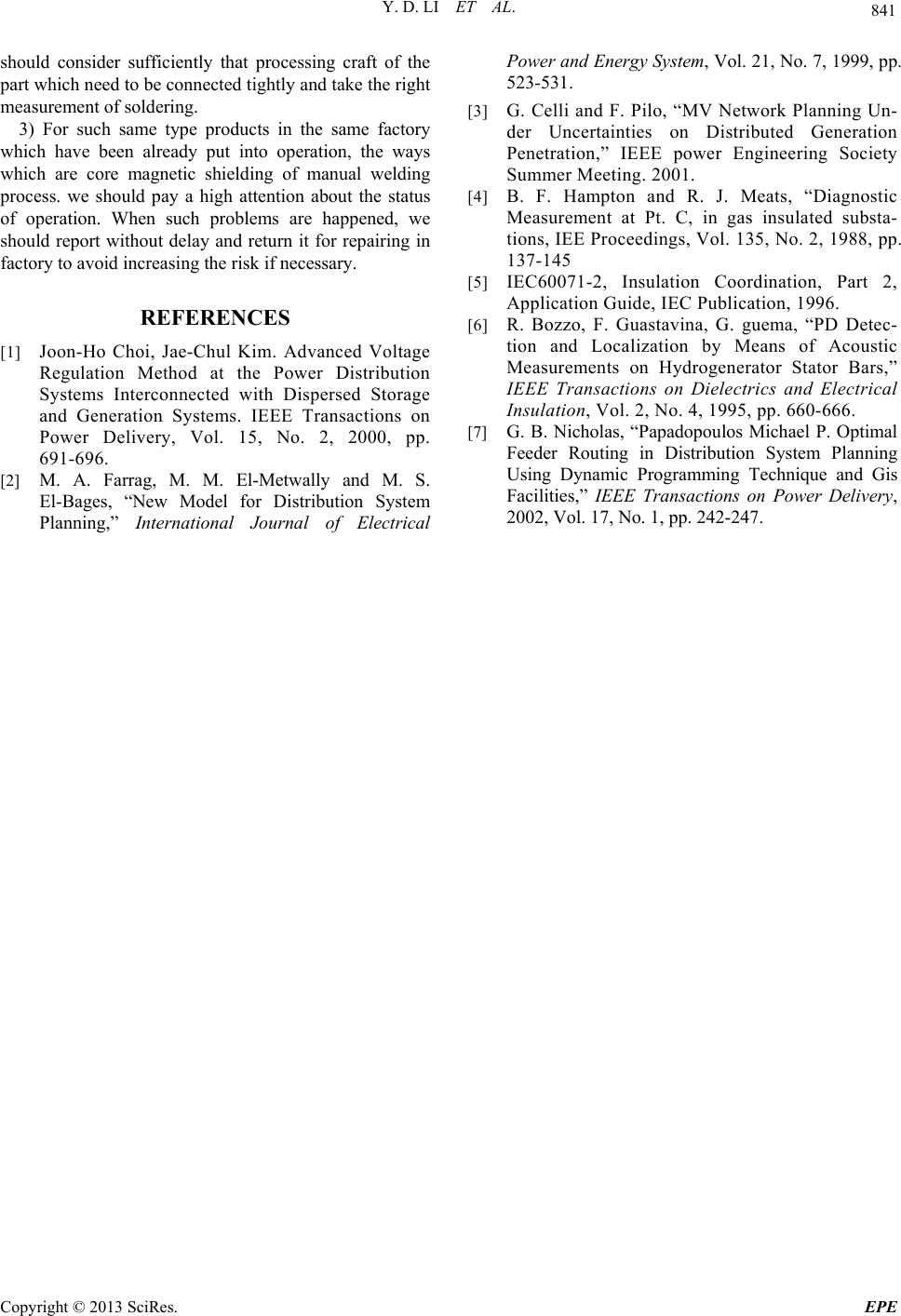 Y. D. LI ET AL. Copyright © 2013 SciRes. EPE 841 should consider sufficiently that processing craft of the part which need to be connected tightly and take the right measurement of soldering. 3) For such same type products in the same factory which have been already put into operation, the ways which are core magnetic shielding of manual welding process. we should pay a high attention about the status of operation. When such problems are happened, we should report without delay and return it for repairing in factory to avoid increasing the risk if necessary. REFERENCES [1] Joon-Ho Choi, Jae-Chul Kim. Advanced Voltage Regulation Method at the Power Distribution Systems Interconnected with Dispersed Storage and Generation Systems. IEEE Transactions on Power Delivery, Vol. 15, No. 2, 2000, pp. 691-696. [2] M. A. Farrag, M. M. El-Metwally and M. S. El-Bages, “New Model for Distribution System Planning,” International Journal of Electrical Power and Energy System, Vol. 21, No. 7, 1999, pp. 523-531. [3] G. Celli and F. Pilo, “MV Network Planning Un- der Uncertainties on Distributed Generation Penetration,” IEEE power Engineering Society Summer Meeting. 2001. [4] B. F. Hampton and R. J. Meats, “Diagnostic Measurement at Pt. C, in gas insulated substa- tions, IEE Proceedings, Vol. 135, No. 2, 1988, pp. 137-145 [5] IEC60071-2, Insulation Coordination, Part 2, Application Guide, IEC Publication, 1996. [6] R. Bozzo, F. Guastavina, G. guema, “PD Detec- tion and Localization by Means of Acoustic Measurements on Hydrogenerator Stator Bars,” IEEE Transactions on Dielectrics and Electrical Insulation, Vol. 2, No. 4, 1995, pp. 660-666. [7] G. B. Nicholas, “Papadopoulos Michael P. Optimal Feeder Routing in Distribution System Planning Using Dynamic Programming Technique and Gis Facilities,” IEEE Transactions on Power Delivery, 2002, Vol. 17, No. 1, pp. 242-247. |