Paper Menu >>
Journal Menu >>
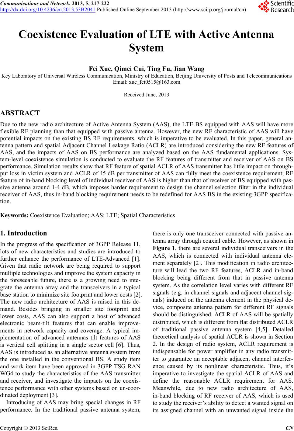 Communications and Network, 2013, 5, 217-222 http://dx.doi.org/10.4236/cn.2013.53B2041 Published Online September 2013 (http://www.scirp.org/journal/cn) Coexistence Evaluation of LTE with Active Antenna System Fei Xue, Qimei Cui, Ting Fu, Jian Wang Key Laboratory of Universal Wireless Communication, Ministry of Education, Beijing University of Posts and Telecommunications Email: xue_fei0515@163.com Received June, 2013 ABSTRACT Due to the new radio architecture of Active Antenna System (AAS), the LTE BS equipped with AAS will have more flexible RF planning than that equipped with passive antenna. However, the new RF characteristic of AAS will have potential impacts on the existing BS RF requirements, which is imperative to be evaluated. In this paper, general an- tenna pattern and spatial Adjacent Channel Leakage Ratio (ACLR) are introduced considering the new RF features of AAS, and the impacts of AAS on BS performance are analyzed based on the AAS fundamental applications. Sys- tem-level coexistence simulation is conducted to evaluate the RF features of transmitter and receiver of AAS on BS performance. Simulation results show that RF feature of spatial ACLR of AAS transmitter has little impact on thro ugh- put loss in victim system and ACLR of 45 dB per transmitter of AAS can fully meet the coexistence requirement; RF feature of in-band blocking level of individual receiver of AAS is higher than that of receiver of BS equipped with pas- sive antenna around 1-4 dB, which imposes harder requirement to design the channel selection filter in the individual receiver of AAS, thus in-band blocking requirement needs to be redefined for AAS BS in the existing 3GPP specifica- tion. Keywords: Coexistence Evaluation; AAS; LTE; Spatial Characteristics 1. Introduction In the progress of the specification of 3GPP Release 11, lots of new characteristics and studies are introduced to further enhance the performance of LTE-Advanced [1]. Given that radio network are being required to support multiple technologies and improve the system capacity in the foreseeable future, there is a growing need to inte- grate the antenna array and the transceivers in a typical base station to minimize site footprint and lower costs [2]. The new radio architecture of AAS is raised in this de- mand. Besides bringing in smaller site footprint and lower costs, AAS can also support a host of advanced electronic beam-tilt features that can enable improve- ments in network capacity and coverage. A typical im- plementation of advanced antennas tilt features of AAS is vertical cell splitting in a single sector cell [6]. Thus, AAS is introduced as an altern ative antenna system from the one installed in the conventional BS. A study item and work item have been approved in 3GPP TSG RAN WG4 to study the characteristics of the AAS transmitter and receiver, and investigate the impacts on the coexis- tence performance with other systems based on un-coor- dinated deployment [3]. Introducing of AAS may bring special changes in RF performance. In the traditional passive antenna system, there is only one transceiver connected with passive an- tenna array through coaxial cable. However, as shown in Figure 1, there are several individual transceivers in the AAS, which is connected with individual antenna ele- ment separately [2]. This modification in radio architec- ture will lead the two RF features, ACLR and in-band blocking being different from that in passive antenna system. As the correlation level varies with different RF signals (e.g. in channel signals and adjacent channel sig- nals) induced on the antenna element in the physical de- vice, composite antenna pattern for different RF signals should be distinguished. ACLR of AAS will be spatially distributed, which is different from flat distributed ACLR of traditional passive antenna system [4,5]. Detailed theoretical analysis of spatial ACLR is shown in Section 2. In the design of radio system, ACLR requirement is indispensable for power amplifier in any radio transmit- ter to guarantee an acceptable adjacent channel interfer- ence caused by its nonlinear characteristic. Thus, it’s imperative to investigate the spatial ACLR of AAS and define the reasonable ACLR requirement for AAS. Meanwhile, due to new radio architecture of AAS, in-band blocking of RF receiver of AAS, which is used to study the receiver’s ability to detect a wan ted sign al on its assigned channel with an unwanted signal inside the C opyright © 2013 SciRes. CN 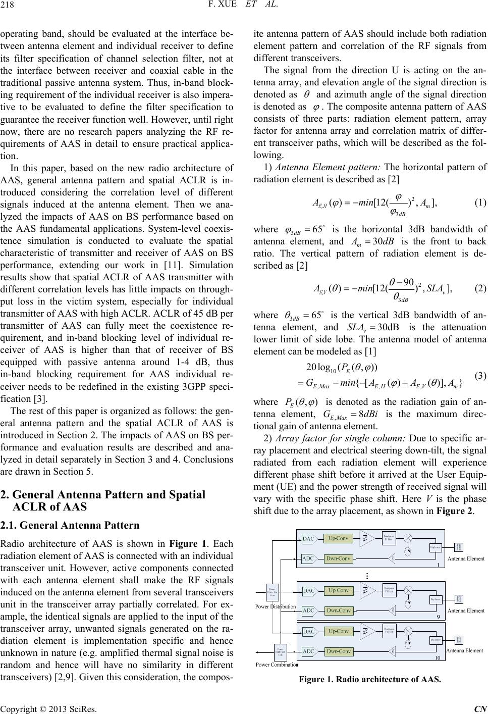 F. XUE ET AL. 218 operating band, should be evaluated at the interface be- tween antenna element and individual receiver to define its filter specification of channel selection filter, not at the interface between receiver and coaxial cable in the traditional passive antenna system. Thus, in-band block- ing requirement of the individual receiver is also impera- tive to be evaluated to define the filter specification to guarantee the receiver function well. However, until right now, there are no research papers analyzing the RF re- quirements of AAS in detail to ensure practical applica- tion. In this paper, based on the new radio architecture of AAS, general antenna pattern and spatial ACLR is in- troduced considering the correlation level of different signals induced at the antenna element. Then we ana- lyzed the impacts of AAS on BS performance based on the AAS fundamental applications. System-level coexis- tence simulation is conducted to evaluate the spatial characteristic of transmitter and receiver of AAS on BS performance, extending our work in [11]. Simulation results show that spatial ACLR of AAS transmitter with different correlation levels has little impacts on through- put loss in the victim system, especially for individual transmitter of AAS with high ACLR. ACLR of 45 dB per transmitter of AAS can fully meet the coexistence re- quirement, and in-band blocking level of individual re- ceiver of AAS is higher than that of receiver of BS equipped with passive antenna around 1-4 dB, thus in-band blocking requirement for AAS individual re- ceiver needs to be redefined in the existing 3GPP speci- fication [3]. The rest of this paper is organized as follows: the gen- eral antenna pattern and the spatial ACLR of AAS is introduced in Section 2. The impacts of AAS on BS per- formance and evaluation results are described and ana- lyzed in detail separately in Section 3 and 4. Con clusions are drawn in Section 5. 2. General Antenna Pattern and Spatial ACLR of AAS 2.1. General Antenna Pattern Radio architecture of AAS is shown in Figure 1. Each radiation element of AAS is connected with an individual transceiver unit. However, active components connected with each antenna element shall make the RF signals induced on the antenna element from several transceivers unit in the transceiver array partially correlated. For ex- ample, the identical sign als are applied to the inpu t of the transceiver array, unwanted signals generated on the ra- diation element is implementation specific and hence unknown in nature (e.g. amplified thermal signal noise is random and hence will have no similarity in different transceivers) [2,9]. Given this consideration, the compos- ite antenna pattern of AAS should include both radiation element pattern and correlation of the RF signals from different transceivers. The signal from the direction U is acting on the an- tenna array, and elevation angle of the signal direction is denoted as and azimuth angle of the signal direction is denoted as . The composite antenna pattern of AAS consists of three parts: radiation element pattern, array factor for antenna array and correlation matrix of differ- ent transceiver paths, which will be described as the fol- lowing. 1) Antenna Element pattern: The horizontal pattern of radiation element is described as [2] 2 3 ()[12() ,], m dB A min A E,H (1) where 3 is the horizontal 3dB bandwidth of antenna element, and 65 dB 30 m A dB is the front to back ratio. The vertical pattern of radiation element is de- scribed as [2] 2 3 90 ()[12() ,], v dB A min SLA E,V (2) where 3 is the vertical 3dB bandwidth of an- tenna element, and is the attenuation lower limit of side lobe. The antenna model of antenna element can be modeled as [1] 65 dB 30dB v SLA 10 ,,, 20log((,)) {[()()], } E E MaxEHEVm P GminAA A (3) where (,) E P is denoted as the radiation gain of an- tenna element, ,8 EMax iGdB is the maximum direc- tional gain of antenna element. 2) Array factor for single column: Due to specific ar- ray placement and electrical steering down-tilt, the signal radiated from each radiation element will experience different phase shift before it arrived at the User Equip- ment (UE) and the power strength of received signal will vary with the specific phase shift. Here V is the phase shift due to the array placement, as shown in Figure 2. Figure 1. Radio architecture of AAS. Copyright © 2013 SciRes. CN 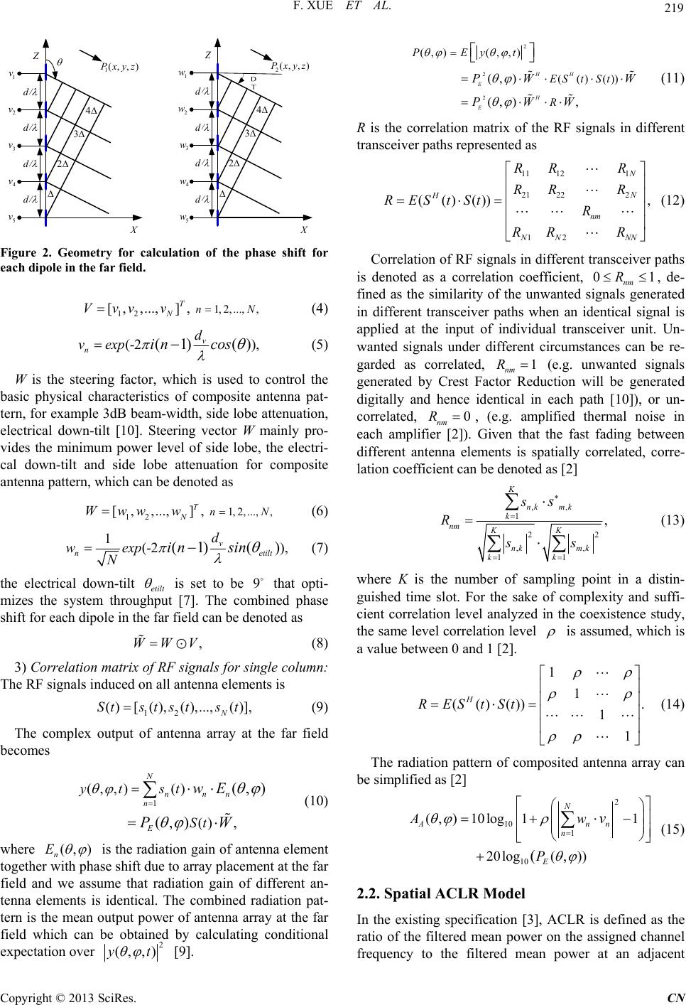 F. XUE ET AL. 219 X Z 2 3 4 1 v 2 v 3 v 4 v 5 v 1 (,,)Pxyz d d d d X Z 2 3 4 3 w 4 w 5 w 2 (,,) P xyz d d d d 1 w 2 w Figure 2. Geometry for calculation of the phase shift for each dipole in the far field. 12 1,2,...,,[,,...,], T NnVvv vN (4) (-2 ),(1) () v n d v expin cos (5) W is the steering factor, which is used to control the basic physical characteristics of composite antenna pat- tern, for example 3dB beam-width, side lobe attenuation, electrical down-tilt [10]. Steering vector W mainly pro- vides the minimum power level of side lobe, the electri- cal down-tilt and side lobe attenuation for composite antenna pattern, which can be denoted as 12 1,2,...,,[,,...,], T NnWwwwN (6) 1(-2 ), (1)() v n etilt d w exp Nin sin (7) the electrical down-tilt etilt is set to be that opti- mizes the system throughput [7]. The combined phase shift for each dipole in the far field can be denoted as 9 ,WWV (8) 3) Correlation matrix of RF signals for single column: The RF signals induced on all antenna elements is 12 ()[ (),(),...,()], N Sts tstst (9) The complex output of antenna array at the far field becomes 1 (,,) () () (,) (,) , N nnn n E yt st St wE PW (10) where (,) n E is the radiation gain of antenna element together with phase shift due to array placement at the far field and we assume that radiation gain of different an- tenna elements is identical. The combined radiation pat- tern is the mean output power of antenna array at the far field which can be obtained by calculating conditional expectation over 2 (,,)yt [9]. 2 2 2 (, )(,,) (()()) (,) (,) , HH E H E PEyt ESt St R PW PWW W (11) R is the correlation matrix of the RF signals in different transceiver paths represented as 11 121 21 222 12 (()()) N N H nm NN NN RR R RR R REStSt R RR R , (12) Correlation of RF signals in different transceiv er paths is denoted as a correlation coefficient, , de- fined as the similarity of the unwanted signals generated in different transceiver paths when an identical signal is applied at the input of individual transceiver unit. Un- wanted signals under different circumstances can be re- garded as correlated, (e.g. unwanted signals generated by Crest Factor Reduction will be generated digitally and hence identical in each path [10]), or un- correlated, 01 nm R 1 nm R 0 nm R , (e.g. amplified thermal noise in each amplifier [2]). Given that the fast fading between different antenna elements is spatially correlated, corre- lation coefficient can be denoted as [2] ,, 1 22 ,, 11 , K nk mk k nm KK nk mk kk s R ss s (13) where K is the number of sampling point in a distin- guished time slot. For the sake of complexity and suffi- cient correlation level analyzed in the coexistence study, the same level correlation level is assumed, which is a value between 0 and 1 [2]. 1 1 (()()) 1 1 H REStSt . (14) The radiation pattern of composited antenna array can be simplified as [2] 2 10 1 10 (,) 10log11 20log( ,)) ( N An n E Aw P v n (15) 2.2. Spatial ACLR Model In the existing specification [3], ACLR is defined as the ratio of the filtered mean power on the assigned channel frequency to the filtered mean power at an adjacent Copyright © 2013 SciRes. CN 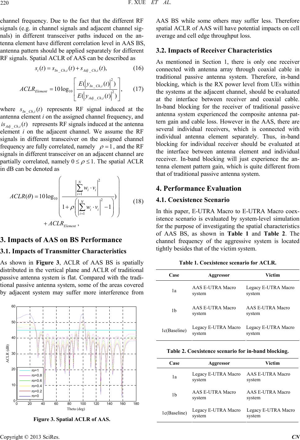 F. XUE ET AL. 220 channel frequency. Due to the fact that the different RF signals (e.g. in channel signals and adjacent channel sig- nals) in different transceiver paths induced on the an- tenna element have different correlation level in AAS BS, antenna pattern should be applied separately for different RF signals. Spatial ACLR of AAS can be described as _, _, () ()(), iInChiAdjChi s ts tst (16) 2 _, 10 2 _, (()) 10log , (() InCh i Element AdjCh i Ey t ACLR Eyt ) (17) where _, () InCh i s t () represents RF signal induced at the antenna element i on the assigned channel frequency, and _,AdjCh i i s t represents RF signals induced at the antenna element i on the adjacent channel. We assume the RF signals in different transceiver on the assigned channel frequency are fully correlated, namely 1 1. , and the RF signals in different transceiver on an adjacent channel are partially correlated, namely 0 The spatial ACLR in dB can be denoted as 2 1 10 2 1 () 10log) 11 , N ii i N ii i Element wv ACLR wv ACLR (18) 3. Impacts of AAS on BS Performance 3.1. Impacts of Transmitter Characteristics As shown in Figure 3, ACLR of AAS BS is spatially distributed in the vertical plane and ACLR of traditional passive antenna system is flat. Compared with the tradi- tional passive antenna system, some of the areas covered by adjacent system may suffer more interference from 020 40 60 80100 120 140 160 180 0 10 20 30 40 50 60 T het a ( de g) ACLR (d B) ro=1 ro=0 .8 ro=0 .6 ro=0 .4 ro=0 .2 ro=0 Figure 3. Spatial ACLR of AAS. AAS BS while some others may suffer less. Therefore spatial ACLR of AAS will have potential impacts on cell average and cell edge throughput loss. 3.2. Impacts of Receiver Characteristics As mentioned in Section 1, there is only one receiver connected with antenna array through coaxial cable in traditional passive antenna system. Therefore, in-band blocking, which is the RX power level from UEs within the systems at the adjacent channel, should be evaluated at the interface between receiver and coaxial cable. In-band blocking for the receiver of traditional passive antenna system experienced the composite antenna pat- tern gain and cable loss. However in the AAS, there are several individual receivers, which is connected with individual antenna element separately. Thus, in-band blocking for individual receiver should be evaluated at the interface between antenna element and individual receiver. In-band blocking will just experience the an- tenna element pattern gain, which is quite different from that of traditional passive antenna system. 4. Performance Evaluation 4.1. Coexistence Scenario In this paper, E-UTRA Macro to E-UTRA Macro coex- istence scenario is evaluated by system-level simulation for the purpose of investigating the spatial characteristics of AAS BS, as shown in Table 1 and Table 2. The channel frequency of the aggressive system is located tightly besides that of the victim system. Table 1. Coexistence scenario for ACLR. Case Aggressor Victim 1a AAS E-UTRA Macro system Legacy E-UTRA Macro system 1b AAS E-UTRA Macro system AAS E-UTRA Macro system 1c(Baseline) Legacy E-UTRA Macro system Legacy E-UTRA Macro system Table 2. Coexistence scenario for in-band blocking. Case Aggressor Victim 1a Legacy E-UTRA Macro system AAS E-UTRA Macro system 1b AAS E-UTRA Macro system AAS E-UTRA Macro system 1c(Baseline) Legacy E-UTRA Macro system Legacy E-UTRA Macro system Copyright © 2013 SciRes. CN 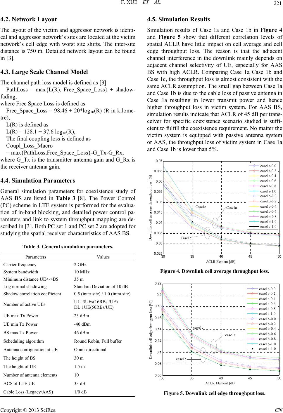 F. XUE ET AL. 221 4.2. Network Layout The layout of the victim and aggressor network is identi- cal and aggressor network’s sites are located at the victim network’s cell edge with worst site shifts. The inter-site distance is 750 m. Detailed network layout can be found in [3]. 4.3. Large Scale Channel Model The channel path loss model is defined as [3] PathLoss = max{L(R), Free_Space_Loss} + shadow- fading, where Free Space Loss is defined as Free_Space_Loss = 98.46 + 20*log10(R) (R in kilome- tre), L(R) is defined as L(R) = 128.1 + 37.6 log10(R), The final coupling loss is defined as Coupl_Loss_Macro = max{PathLoss,Free_Space_Loss}-G_Tx-G_Rx, where G_Tx is the transmitter antenna gain and G_Rx is the receiver antenna gain. 4.4. Simulation Parameters General simulation parameters for coexistence study of AAS BS are listed in Table 3 [8]. The Power Control (PC) scheme in LTE system is performed for the evalua- tion of in-band blocking, and detailed power control pa- rameters and link to system throughput mapping are de- scribed in [3]. Both PC set 1 and PC set 2 are adopted for studying the spatial receiver characteristics of AAS BS. Table 3. General simulation parameters. Parameters Values Carrier freque nc y 2 GHz System bandwidth 10 MHz Minimum dist ance U E<->BS 35 m Log normal sha d ow i n g Standard Deviation of 10 d B Shadow correlation coefficient 0.5 ( inter site) / 1.0 (intra site) Number of active UEs UL: 3UEs(16RBs /UE) DL:1UE(50RBs/UE) UE max Tx Power 23 dBm UE min Tx Power -40 dBm BS max Tx Power 46 dBm Scheduling algorithm Round Robin, Full buffer Antenna configuration at UE Omni-dire ctional The height of BS 30 m The height of UE 1.5 m Number of antenna elements 10 ACS of LTE UE 33 dB Cable Loss (Legacy/AAS) 1/0 dB 4.5. Simulation Results Simulation results of Case 1a and Case 1b in Figure 4 and Figure 5 show that different correlation levels of spatial ACLR have little impact on cell average and cell edge throughput loss. The reason is that the adjacent channel interference in the downlink mainly depends on adjacent channel selectivity of UE, especially for AAS BS with high ACLR. Comparing Case 1a Case 1b and Case 1c, the throughput loss is almost consistent with the same ACLR assumption. The small gap between Case 1a and Case 1b is due to the cable loss of passive antenna in Case 1a resulting in lower transmit power and hence higher throughput loss in victim system. For AAS BS, simulation results indicate that ACLR of 45 dB per trans- ceiver for specific coexistence scenario studied is suffi- cient to fulfill the coexistence requirement. No matter the victim system is equipped with passive antenna system or AAS, the throughput loss of victim system in Case 1a and Case 1b is lower than 5%. 30 35 40 45 50 0. 025 0.03 0. 035 0.04 0. 045 0.05 0. 055 0.06 0. 065 0.07 ACLR Element [ dB] Do wn lin k ce ll av er age t hr ou ghp ut lo ss [ % ] case1a-0.0 case1a-0.2 case1a-0.4 case1a-0.6 case1a-0.8 case1a-1.0 case1b-0.0 case1b-0.2 case1b-0.4 case1b-0.6 case1b-0.8 case1b-1.0 case1c-1.0 Cas e 1a Case1 c Case1b Figure 4. Downlink cell ave r a ge throughput loss. 30 35404550 0. 06 0. 08 0.1 0. 12 0. 14 0. 16 0. 18 0.2 0. 22 ACLR Eleme n t [d B] Downlink cell edge througput loss [%] case1a-0.0 case1a-0.2 case1a-0.4 case1a-0.6 case1a-0.8 case1a-1.0 case1b-0.0 case1b-0.2 case1b-0.4 case1b-0.6 case1b-0.8 case1b-1.0 case1c-1.0 case1a case1c case1b Figure 5. Downlink cell edge throughput loss. Copyright © 2013 SciRes. CN  F. XUE ET AL. Copyright © 2013 SciRes. CN 222 Case 1aCas e 1 bCas e 1 c -60 -55 -50 -45 -40 -30 -20 -10 0 Uplink in-band blocking [dBm] PC1 PC2 -42. 27 -51.47 -42.61 -51.79 -43. 66 -55.61 Figure 6. Uplink in-band blocking. Comparing Case 1a and Case 1c in Figure 6, the up- link in-band blocking interference signals presented at the AAS individual receiver are higher than that of the receiver of BS equipped with traditional passive antenna for both PC set 1 and PC set 2 around 1-4 dB. The block- ing interference signals of Case1a are a little higher than that of Case 1b. The reason is that the aggressive BS in Case 1a equipped with traditional passive antenna has higher cable loss than AAS, which leads to higher trans- mit power of aggressive UE and hence higher blocking interference signals in victim system. The simulation results indicate that it is necessary to redefine the block- ing requirement for AAS individual receiver to design the channel selection filter ensuring performance and stability under different coexistence scenarios. 5. Conclusions In this paper, the spatial transmitter and receiver charac- teristics of AAS are investigated and evaluated through system level coexistence simulation. Simulation result show that different correlation level has little impact on throughput loss caused by spatial ACLR of AAS, and ACLR of 45 dB per transmitter of AAS is sufficient to meet the coexistence requirement. And in-band blocking level of AAS individual receiver is higher than that of the receiver of BS equipped with traditional passive antenna around 1-4 dB, thus it is necessary to redefine in-band blocking requirement for the individual receiver of AAS in 3GPP LTE existing requirement. 6. Acknowledgements The research work is supported by National Science and Technology Major Project of China (2012ZX03001039, 2013ZX03001018), Beijing City Science and Technol- ogy Project (D121100002112002). REFERENCES [1] 3GPP, “Overview of 3GPP Release 11 V0.1.4”, Mar.2013. [2] 3GPP TR 37.840 V0.3.0, “Study of AAS Base Station”, Dec.2012. [3] 3GPP TR 36.942 V10.3.0, “E-UTRA Radio Frequency (RF) System Scenario,” June.2012. [4] 3GPP TR 25.816 V8.0.0, “UMTS 900 MHZ Work Item Technical Report,” Sept.2009. [5] 3GPP TR 36.814 V9.0.0, “Further Advancements for E-UTRA Physical Layer Aspect,” Mar.2010. [6] O. N. C. Yilmaz, S. Hamalainen and J. Hamalainen, “System Level Analysis of Vertical Sectorization for 3GPP LTE,” IEEE 6 International Symposium On Wire- less Communication System (ISSWCS), pp. 453-457, Oct.2009. [7] 3GPP R4-124171, “On the Down-tilt for 3D Coexistence Simulation,” 3GPP TSG RAN WG4 Meeting#64. [8] 3GPP R4-122397, “Text Proposal for Simulation As- sumptions for AAS,” 3GPP TSG RAN WG4 Meeting#63. [9] 3GPP R4-123245, “Correction on Composite Array Ra- diation Pattern for AAS,” 3GPP TSG WG RAN4 Meet- ing#64bis. [10] 3GPP R4-123925, “Discussion for Composite Radiation Pattern of AAS”, 3GPP TSG RAN WG4 Meeting#64. [11] P. C. Kang, Q. M. Cui, S. Chen and Y. J. Liu, “Perform- ance Evaluation on Coexistence of LTE with Active An- tenna Array System,” IEEE23rd International Symposium on Personal Indoor and Mobile Radio Communication (PIMRC), pp. 1066-1070, Sept. 2012. |