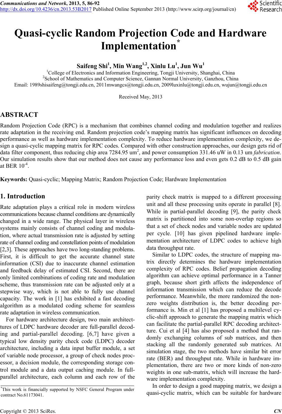
 Communications and Network, 2013, 5, 86-92 http://dx.doi.org/10.4236/cn.2013.53B2017 Published Online September 2013 (http://www.scirp.org/journal/cn) Quasi-cyclic Random Projection Code and Hardware Implementation* Saifeng Shi1, Min Wang1,2, X in lu Lu1, J un Wu1 1College of Electronics and Information Engineer ing, Tongji University, Shanghai, China 2School of Mathematics and Computer Science, Gannan Normal University, Ganzhou, China Email: 1989shisaifeng@tongji.edu.cn, 2011mwangcs@tongji.edu.cn, 2009luxinlu @tongj i.edu.cn, wujun @tongji.edu.cn Received May, 2013 ABSTRACT Random Projection Code (RPC) is a mechanism that combines channel coding and modulation together and realizes rate adaptation in the receiving end. Random projection code’s mapping matrix has significant influences on decoding performance as well as hardware implementation complexity. To reduce hardware implementation complexity, we de- sign a quasi-cyclic mapping matrix for RPC codes. Compared with other construction approaches, our design gets rid of data filter component, thus redu cing chip area 728 4.95 um2, and pow er con sumption 331.4 6 uW in 0.13 um fabrication. Our simulation results show that our method does not cause any performance loss and even gets 0.2 dB to 0.5 dB gain at BER 10-4. Keywords: Quasi-cyclic; Mapping Matrix; Random Projection Code; Hardware Implementation 1. Introduction Rate adaptation plays a critical role in modern wireless communications because channel conditions are dynamically changed in a wide range. The physical layer in wireless systems mainly consists of channel coding and modula- tion, where actual transmission rate is adju sted by setting rate of channel coding and constellation points of modulation [2,3]. These approaches have two long-standing problems. First, it is difficult to get the accurate channel state information (CSI) due to inaccurate channel estimation and feedback delay of estimated CSI. Second, there are only limited combinations of coding rate and modulation scheme, thus transmission rate can be adjusted only at a stepwise way, which is not able to fully use channel capacity. The work in [1] has exhibited a fast decoding algorithm as a modulated coding scheme for seamless rate adaptation in wireless communication. For hardware architecture design, two main architect- tures of LDPC hardware decoder are full-parallel decod- ing and partial-parallel decoding. [6,7] have given a typical low density parity check code (LDPC) decoder architecture, including a data input buffer module, a set of variable node processor, a group of check nodes proc- essor, a decision module, the corresponding storage con- trol module and a data output caching module. In full- parallel architecture, each column and each row of the parity check matrix is mapped to a different processing unit and all these pro cessing units operate in parallel [8]. While in partial-parallel decoding [9], the parity check matrix is partitioned into some non-overlap regions so that a set of check nodes and variable nodes are updated per cycle. [10] has given pipelined hardware imple- mentation architecture of LDPC codes to achieve high data throughput rate. Similar to LDPC codes, the structure of mapping ma- trix directly determines the hardware implementation complexity of RPC codes. Belief propagation decoding algorithm can achieve optimal performance in a Tanner graph, because short girth affects the independence of information transmission which can reduce the decode performance. Meanwhile, the more randomized the non- zero weights distribution is, the better decoding per- formance is. Min et al [1] has proposed a multilevel cy- clic-shift approach to generate the mapping matrix which can facilitate the partial-parallel RPC decoding architect- ture. Cui et al [4] has also proposed a method that ran- domly exchanging columns of sub matrices, and then stacking all the randomly generated sub matrices. At simulation stage, the two methods have similar bit error rate (BER) and throughput rate. While in hardware im- plementation, there are two or more kinds of non-zero weights in one sub-matrix, which will increase the hard- ware implementation complexity. In order to design a good mapping matrix, we design a quasi-cyclic matrix, which can be suitable for hardware *This work is financially supported by NSFC General Program under contract No.6117304 1 . C opyright © 2013 SciRes. CN 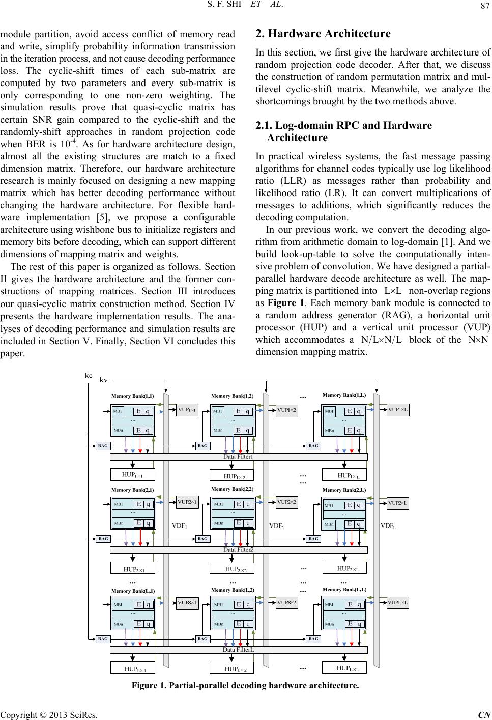 S. F. SHI ET AL. 87 module partition, avoid access conflict of memory read and write, simplify probability information transmission in the iteration process, and not cause decoding performance loss. The cyclic-shift times of each sub-matrix are computed by two parameters and every sub-matrix is only corresponding to one non-zero weighting. The simulation results prove that quasi-cyclic matrix has certain SNR gain compared to the cyclic-shift and the randomly-shift approaches in random projection code when BER is 10-4. As for hardware architecture design, almost all the existing structures are match to a fixed dimension matrix. Therefore, our hardware architecture research is mainly focused on designing a new mapping matrix which has better decoding performance without changing the hardware architecture. For flexible hard- ware implementation [5], we propose a configurable architecture using wishbone bus to initialize registers and memory bits before decoding, which can support different dimensions of mapping matrix and weights. The rest of this paper is organized as follows. Section II gives the hardware architecture and the former con- structions of mapping matrices. Section III introduces our quasi-cyclic matrix construction method. Section IV presents the hardware implementation results. The ana- lyses of decoding performance and simulation results are included in Section V. Finally, Section VI concludes this paper. 2. Hardware Architecture In this section, we first give the hardware architecture of random projection code decoder. After that, we discuss the construction of random permutation matrix and mul- tilevel cyclic-shift matrix. Meanwhile, we analyze the shortcomings brought by the two methods above. 2.1. Log-domain RPC and Hardware Architecture In practical wireless systems, the fast message passing algorithms for channel codes typically use log lik elihood ratio (LLR) as messages rather than probability and likelihood ratio (LR). It can convert multiplications of messages to additions, which significantly reduces the decoding computation. In our previous work, we convert the decoding algo- rithm from arithmetic domain to log-domain [1]. And we build look-up-table to solve the computationally inten- sive problem of convolution. We have designed a partial- parallel hardware decode architecture as well. The map- ping matrix is partitioned into non-overlap regions as Figure 1. Each memory bank module is connected to a random address generator (RAG), a horizontal unit processor (HUP) and a vertical unit processor (VUP) which accommodates a LL LNL block of the N dimension mapping matrix. Figure 1. Partial-parallel decoding hardware architecture. Copyright © 2013 SciRes. CN 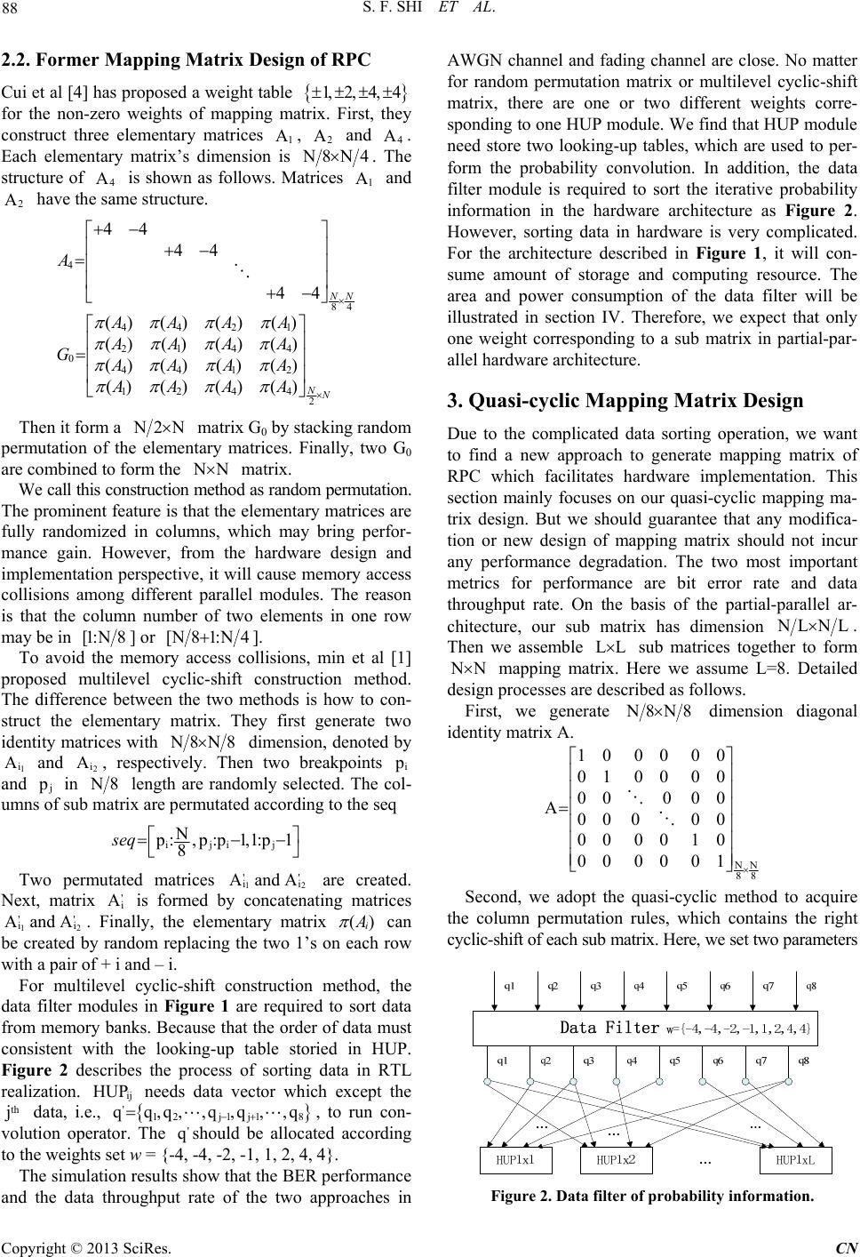 S. F. SHI ET AL. 88 2.2. Former Mapping Matrix Design of RPC Cui et al [4] has proposed a weight table 1, 2, 4, 4 2 A4 A for the non-zero weights of mapping matrix. First, they construct three elementary matrices , and . Each elementary matrix’s dimension is 1 A 8N4. The structure of is shown as follows. Matrices and have the same structure. 4 A1 A 2 A 4 84 4421 2144 04412 1244 2 4444 44 () () ()() ()()() () () ()()() ()() () () N NN A AAAA AAAA GAAAA AAAA Then it form a 2N matrix G0 by stacking random permutation of the elementary matrices. Finally, two G0 are combined to form the N matrix. We call this construction method as random permutation. The prominent feature is that the elementary matrices are fully randomized in columns, which may bring perfor- mance gain. However, from the hardware design and implementation perspective, it will cause memory access collisions among different parallel modules. The reason is that the column number of two elements in one row may be in [1:N8 ] or [N 81:N4]. To avoid the memory access collisions, min et al [1] proposed multilevel cyclic-shift construction method. The difference between the two methods is how to con- struct the elementary matrix. They first generate two identity matrices with 8N8 dimension, denoted by 1 and , respectively. Then two breakpoints i A2 i Ai and j in 8 length are randomly selected. The col- umns of sub matrix are permutated according to the seq iji j N :,p:p1,1:p1 8 seq ' Two permutated matrices 12 i are created. Next, matrix is formed by concatenating matrices 12 . Finally, the elementary matrix ' i Aand A ' i A ' i ' i Aand A () i can be created by random replacing the two 1’s on each row with a pair of + i and – i. For multilevel cyclic-shift construction method, the data filter modules in Figure 1 are required to sort data from memory banks. Because that the order of data must consistent with the looking-up table storied in HUP. Figure 2 describes the process of sorting data in RTL realization. needs data vector which except the data, i.e., ij HUP th j ' q12 j1j18 q,q ,,q,q,,q ' q, to run con- volution operator. The should be allocated according to the weights set w = {-4, -4, -2, -1, 1, 2, 4, 4}. The simulation results show that the BER performance and the data throughput rate of the two approaches in AWGN channel and fading channel are close. No matter for random permutation matrix or multilevel cyclic-shift matrix, there are one or two different weights corre- sponding to one HUP module. We find that HUP module need store two looking-up tables, which are used to per- form the probability convolution. In addition, the data filter module is required to sort the iterative probability information in the hardware architecture as Figure 2. However, sorting data in hardware is very complicated. For the architecture described in Figure 1, it will con- sume amount of storage and computing resource. The area and power consumption of the data filter will be illustrated in section IV. Therefore, we expect that only one weight corresponding to a sub matrix in partial-par- allel hardware architecture. 3. Quasi-cyclic Mapping Matrix Design Due to the complicated data sorting operation, we want to find a new approach to generate mapping matrix of RPC which facilitates hardware implementation. This section mainly focuses on our quasi-cyclic mapping ma- trix design. But we should guarantee that any modifica- tion or new design of mapping matrix should not incur any performance degradation. The two most important metrics for performance are bit error rate and data throughput rate. On the basis of the partial-parallel ar- chitecture, our sub matrix has dimension LNL . Then we assemble LL sub matrices together to form N mapping matrix. Here we assume L=8. Detailed design processes are described as follows. First, we generate 8N8 dimension diagonal identity matrix A. NN 88 10 00 00 01 00 00 000 00 A00 000 00 00 10 00 00 01 Second, we adopt the quasi-cyclic method to acquire the column permutation rules, which contains the right cyclic-shift of each sub matrix. Here, we set two parameters Figure 2. Data filter of probability information. Copyright © 2013 SciRes. CN 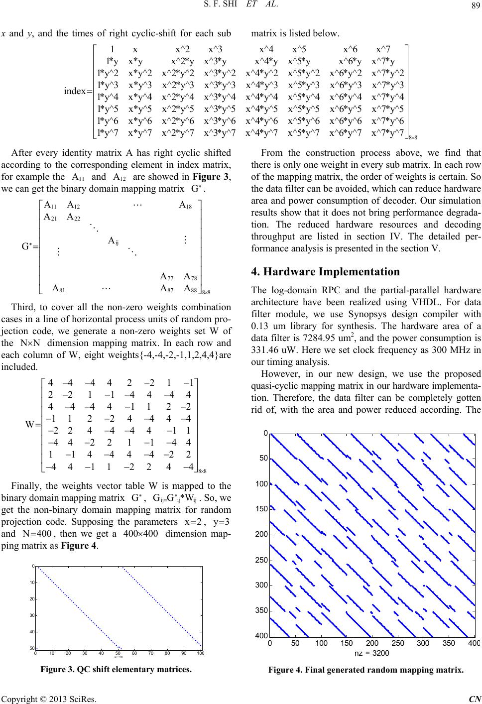 S. F. SHI ET AL. 89 x and y, and the times of right cyclic-shift for each sub matrix is listed below. 1xx^2 x^3x^4 x^5x^6 x^7 1*y x*yx^2*y x^3*yx^4*y x^5*yx^6*yx^7*y 1*y^2x*y^2x^2*y^2x^3*y^2x^4*y^2x^5*y^2x^6*y^2x^7*y^2 1*y^3 x*y^3 x^2*y^3 x^3*y^3 x^4*y^3 x^5*y^3 x^6*y^3 x^7*y^3 index 1*y^4x*y^4x^2*y^4x^3*y^4 1* y^5x *y^5 88 x^4*y^4 x^5*y^4 x^6*y^4 x^7*y^4 x^2*y^5 x^3*y^5 x^4*y^5 x^5*y^5 x^6*y^5 x^7*y^5 1*y^6 x*y^6 x^2*y^6 x^3*y^6 x^4*y^6 x^5*y^6 x^6*y^6 x^7*y^6 1*y^7 x*y^7 x^2*y^7 x^3*y^7 x^4*y^7 x^5*y^7 x^6*y^7 x^7*y^7 After every identity matrix A has right cyclic shifted according to the corresponding element in index matrix, for example the and are showed in Figure 3, we can get the binary domain mapping matrix . 11 A12 A * G 11 1218 21 22 ij * 77 78 818788 88 AA A AA A G AA AAA Third, to cover all the non-zero weights combination cases in a line of horizontal process units of random pro- jection code, we generate a non-zero weights set W of the N dimension mapping matrix. In each row and each column of W, eight weights{-4,-4,-2,-1,1,2,4,4}are included. 88 44 442 211 221 144 44 44441122 11 22444 4 W22444 411 44 2211 44 11444422 441122 44 Finally, the weights vector table W is mapped to the binary domain mapping matrix , . So, we get the non-binary domain mapping matrix for random projection code. Supposing the parameters * G* ijij ij GG*W x2 , y3 and 400, then we get a dimension map- ping matrix as Figure 4. 400400 010 20 30 40 50 60 70 8090 100 0 10 20 30 40 50 nz = 100 Figure 3. QC shift elementary matrices. From the construction process above, we find that there is only one weight in every sub matrix. In each row of the mapping matrix, the order of weights is certain. So the data filter can be avoided, which can reduce hardware area and power consumption of decoder. Our simulation results show that it does not bring performance degrada- tion. The reduced hardware resources and decoding throughput are listed in section IV. The detailed per- formance analysis is presented in the section V. 4. Hardware Implementation The log-domain RPC and the partial-parallel hardware architecture have been realized using VHDL. For data filter module, we use Synopsys design compiler with 0.13 um library for synthesis. The hardware area of a data filter is 7284.95 um2, and the power consumption is 331.46 uW. Here we set clock frequency as 300 MHz in our timing analysis. However, in our new design, we use the proposed quasi-cyclic mapping matrix in our hardware implementa- tion. Therefore, the data filter can be completely gotten rid of, with the area and power reduced according. The 050100150 200 25030035040 0 50 100 150 200 250 300 350 400 nz = 3200 Figure 4. Final generated random mapping matrix. Copyright © 2013 SciRes. CN 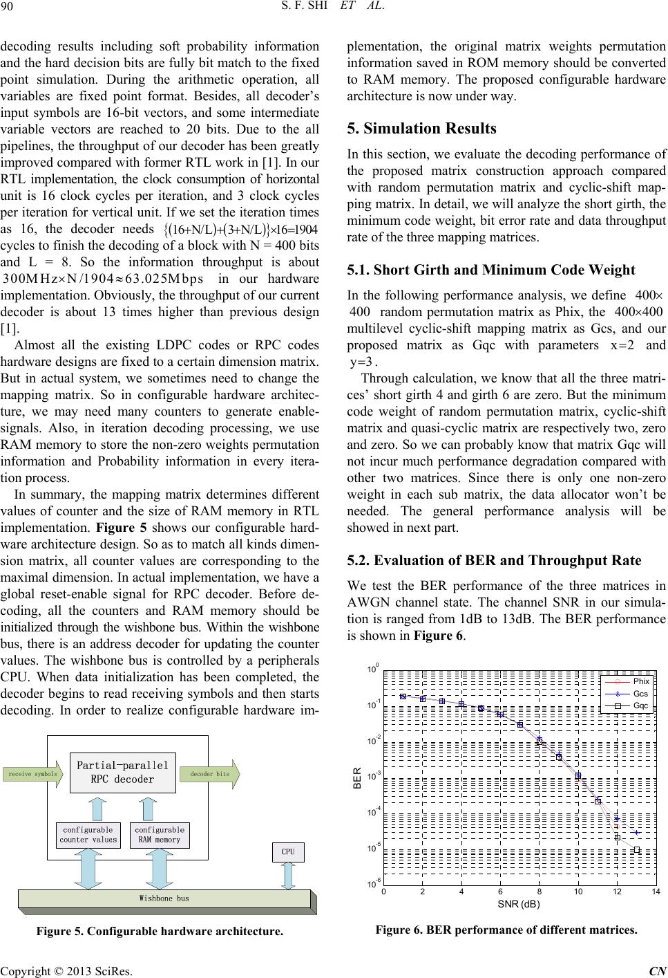 S. F. SHI ET AL. 90 decoding results including soft probability information and the hard decision bits are fully bit match to the fixed point simulation. During the arithmetic operation, all variables are fixed point format. Besides, all decoder’s input symbols are 16-bit vectors, and some intermediate variable vectors are reached to 20 bits. Due to the all pipelines, the throughput of our decoder has been greatly improved compared with former RTL work in [1]. In our RTL implementation, the clock consumption of horizontal unit is 16 clock cycles per iteration, and 3 clock cycles per iteration for vertical unit. If we set the iteration times as 16, the decoder needs 16N/L3 N/L16 1904 25Mbps cycles to finish the decoding of a block with N = 400 bits and L = 8. So the information throughput is about in our hardware implementation. Obviously, the throughput of our current decoder is about 13 times higher than previous design [1]. 300MHz N/190463.0 Almost all the existing LDPC codes or RPC codes hardware designs are fixed to a certain dimension matrix. But in actual system, we sometimes need to change the mapping matrix. So in configurable hardware architec- ture, we may need many counters to generate enable- signals. Also, in iteration decoding processing, we use RAM memory to store the non-zero weights permutation information and Probability information in every itera- tion process. In summary, the mapping matrix determines different values of counter and the size of RAM memory in RTL implementation. Figure 5 shows our configurable hard- ware architecture design. So as to match all kinds dimen- sion matrix, all counter values are corresponding to the maximal dimension. In actual implementation, we have a global reset-enable signal for RPC decoder. Before de- coding, all the counters and RAM memory should be initialized through the wishbone bus. Within the wishbone bus, there is an address decoder for updating the counter values. The wishbone bus is controlled by a peripherals CPU. When data initialization has been completed, the decoder begins to read receiving symbols and then starts decoding. In order to realize configurable hardware im- receive symbolsdecoder bits Figure 5. Configurable hardware architecture. plementation, the original matrix weights permutation information saved in ROM memory should be converted to RAM memory. The proposed configurable hardware architecture is now under way. 5. Simulation Results In this section, we evaluate the decoding performance of the proposed matrix construction approach compared with random permutation matrix and cyclic-shift map- ping matrix. In detail, we will analyze the short girth, the minimum code weight, bit error rate and data throughput rate of the three mapping matrices. 5.1. Short Girth and Minimum Code Weight In the following performance analysis, we define 400 random permutation matrix as Phix, the 400400 400 multilevel cyclic-shift mapping matrix as Gcs, and our proposed matrix as Gqc with parameters x2 and y3 . Through calculation, we know that all the three matri- ces’ short girth 4 and girth 6 are zero. But the minimum code weight of random permutation matrix, cyclic-shift matrix and quasi-cyclic matrix are respectively two, zero and zero. So we can probably know that matrix Gqc will not incur much performance degradation compared with other two matrices. Since there is only one non-zero weight in each sub matrix, the data allocator won’t be needed. The general performance analysis will be showed in next part. 5.2. Evaluation of BER and Throughput Rate We test the BER performance of the three matrices in AWGN channel state. The channel SNR in our simula- tion is ranged from 1dB to 13dB. The BER performance is shown in Figure 6. 0246810 12 14 10 -6 10 -5 10 -4 10 -3 10 -2 10 -1 10 0 SN R (d B) BER Phix Gc s Gqc Figure 6. BER performance of different matrices. Copyright © 2013 SciRes. CN 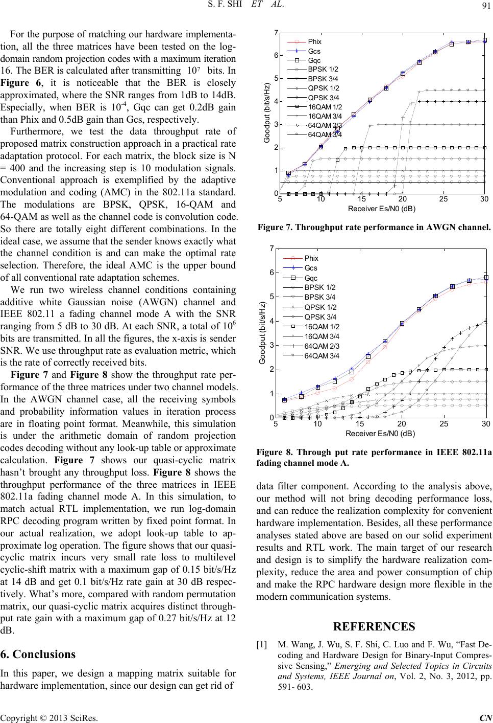 S. F. SHI ET AL. 91 For the purpose of matching our hardware implementa- tion, all the three matrices have been tested on the log- domain random projection codes with a maximum iteration 16. The BER is calculated after transmitting bits. In Figure 6, it is noticeable that the BER is closely approximated, where the SNR ranges from 1dB to 14dB. Especially, when BER is 10-4, Gqc can get 0.2dB gain than Phix and 0.5dB gain than Gcs, res pectively . 7 10 Furthermore, we test the data throughput rate of proposed matrix construction approach in a practical rate adaptation protocol. For each matrix, the block size is N = 400 and the increasing step is 10 modulation signals. Conventional approach is exemplified by the adaptive modulation and coding (AMC) in the 802.11a standard. The modulations are BPSK, QPSK, 16-QAM and 64-QAM as well as the channel code is convolution code. So there are totally eight different combinations. In the ideal case, we assume that the sender knows exactly what the channel condition is and can make the optimal rate selection. Therefore, the ideal AMC is the upper bound of all conventional rate adaptation schemes. We run two wireless channel conditions containing additive white Gaussian noise (AWGN) channel and IEEE 802.11 a fading channel mode A with the SNR ranging from 5 dB to 30 dB. At each SNR, a total of 106 bits are transmitted. In all the figures, the x-axis is sender SNR. We use throughput rate as evaluation metric, which is the rate of correctly received bits. Figure 7 and Figure 8 show the throughput rate per- formance of the three matrices under two channel models. In the AWGN channel case, all the receiving symbols and probability information values in iteration process are in floating point format. Meanwhile, this simulation is under the arithmetic domain of random projection codes decoding without any look-up table or approximate calculation. Figure 7 shows our quasi-cyclic matrix hasn’t brought any throughput loss. Figure 8 shows the throughput performance of the three matrices in IEEE 802.11a fading channel mode A. In this simulation, to match actual RTL implementation, we run log-domain RPC decoding program written by fixed point format. In our actual realization, we adopt look-up table to ap- proximate log operation. The figure shows that our quasi- cyclic matrix incurs very small rate loss to multilevel cyclic-shift matrix with a maximum gap of 0.15 bit/s/Hz at 14 dB and get 0.1 bit/s/Hz rate gain at 30 dB respec- tively. What’s more, compared with random permutation matrix, our quasi-cyclic matrix acquires distinct through- put rate gain with a maximum gap of 0.27 bit/s/Hz at 12 dB. 6. Conclusions In this paper, we design a mapping matrix suitable for hardware implementation, since our design can get rid of 510 15 20 25 30 0 1 2 3 4 5 6 7 R eceiver Es/ N0 ( dB) G oodput ( bit/s/Hz) Phix Gcs Gqc BPSK 1 /2 BPSK 3 /4 QPSK 1/2 QPSK 3/4 16QAM 1/2 16QAM 3/4 64QAM 2/3 64QAM 3/4 Figure 7. Throughput rate per formanc e in AWGN channel. 510 1520 25 30 0 1 2 3 4 5 6 7 R eceiv er Es/N0 ( dB) Go odput (bi t /s /Hz) Phix Gcs Gqc BPSK 1/2 BPSK 3/4 QPSK 1/2 QPSK 3/4 16QAM 1/2 16QAM 3/4 64QAM 2/3 64QAM 3/4 Figure 8. Through put rate performance in IEEE 802.11a fading channel mode A. data filter component. According to the analysis above, our method will not bring decoding performance loss, and can reduce the realization complexity for convenient hardware implementation. Besides, all these performance analyses stated above are based on our solid experiment results and RTL work. The main target of our research and design is to simplify the hardware realization com- plexity, reduce the area and power consumption of chip and make the RPC hardware design more flexible in the modern communication systems. REFERENCES [1] M. Wang, J. Wu, S. F. Shi, C. Luo and F. Wu, “Fast De- coding and Hardware Design for Binary-Input Compres- sive Sensing,” Emerging and Selected Topics in Circuits and Systems, IEEE Journal on, Vol. 2, No. 3, 2012, pp. 591- 603. Copyright © 2013 SciRes. CN  S. F. SHI ET AL. Copyright © 2013 SciRes. CN 92 [2] J. D. Brown, S. Pasupathy and K. N. Plataniotis, “Adap- tive Demodulation Using Rateless Erasure Codes,” IEEE Transactions on Communications, Vol. 54, 2006, pp. 1574-1585. doi:10.1109/TCOMM.2006.881236 [3] A. Gudipati and S. Katti, “Automatic Rate Adaptation,” In Proc. of ACM Hotnets, 2010. doi:10.1145/1868447.1868461 [4] H. Cui, C. Luo, K. Tan, F. Wu and C. W. Chen, “Seam- less Rate Adaptation for Wireless Networking,” in Proc. of ACM MSWiM, 2011, pp. 437-446. [5] G. Masera, F. Quaglio and F. Vacca, “Implementation of a Flexible LDPC Decoder,” IEEE Transactions on Cir- cuits and Systems II: Express Briefs, Vol. 54, No. 6, 2007, pp. 542-546. doi:10.1109/TCSII.2007.894409 [6] Y. Chen and K. Parhi, “Overlapped Message Passing for Quasi-cyclic Low-density Parity Check Codes,” IEEE Transactions on Circuits and Systems I: Regular Papers, Vol. 51, No. 6, 2004, pp. 1106-1113. doi:10.1109/TCSI.2004.826194 [7] G. Masera, F. Quaglio and F. Vacca, “Implementation of a Flexible LDPC Decoder,” Circuits and Systems II: Ex- press Briefs, IEEE Transactions on, Vol. 54, No. 6, 2007, pp. 542-546.doi:10.1109/TCSII.2007.894409 [8] A. Tarable, S. Benedetto and G. Montorsi, “Mapping Interleaving Laws to Parallel Turbo and Ldpc Decoder Architectures,” Information Theory. IEEE Transactions on, Vol. 50, 2004, 2004, pp. 2002 - 2009. [9] M. Mansour and N. Shanbhag, “A 640-mb/s 2048-bit Programmable Ldpc Decoder Chip,” Solid-State Circuits, IEEE Journal of, Vol. 41, 2006, pp. 684-698. doi:10.1109/JSSC.2005.864133 [10] Z. Khan and T. Arslan, “Pipelined Implementation of a Real Time Programmable Encoder for Low Density Par- ity Check Code on a ReconFigureurable Instruction Cell Architecture,” Design, Automation & Test in Europe Conference & Exhibition, 2007. DATE '07, 16-20 April 2007, pp. 1-6.
|