 Communications and Network, 2013, 5, 80-85 http://dx.doi.org/10.4236/cn.2013.53B2016 Published Online September 2013 (http://www.scirp.org/journal/cn) Analysis of Multipath and CW Interference Effects on GNSS Receivers with EMLP Discriminator Bo Qu1, Jiaolong Wei1, Shuangna Zhang2, Liang Bi2 1Department of Electronic and Inform ation Engineering, Huazhong University of Science and Technology, China 2Space Star Technology Co. Ltd, China Email: qubo@hust.edu.cn, jlwei@mail.hust.edu.cn Received May, 2013 ABSTRACT Multipath and continuo us wave (CW) interference may cause severe performance degradation of global navig ation sat- ellite system (GNSS) receivers. This paper analyzes the code tracking performance of early-minus-late power (EMLP) discriminator of GNSS receivers in the presence of multipath and CW interference. An analytical expression of the code tracking error is suggested for EMLP discriminator, and it can be used to assess the effect of multipath and CW inter- ference. The derived expression shows that the combined effects include three components: multipath component; CW interference component and the combined component of multipath and CW interference. The effect of these compo- nents depends on some factors which can be classified into two categories: the receiving environment and the receiver parameters. Numerical results show how these factors affect the tracking performances. It is shown that the proper re- ceiver parameters can suppress the combined effects of multipath and CW interference. Keywords: Multipath; Interference; GNSS; EMLP; Discriminator 1. Introduction GNSS signal is very susceptibility to receiving environ- ment [1-2]. Multipath is the dominant error source in most GNSS applications. Therefore, multipath perform- ance analysis plays a significant role in the analysis of the code tracking performance of GNSS receivers. The multipath error envelope (MEE) is a common way of assessing the multipath performance of a given sig- nal/receiver combination [3]. CW interference is typical radio frequency interference (RFI) which is another error source for GNSS receivers [4, 5]. Thepost-correlati on effects of narrowband interference and partial-band interference have been analyzed in [4, 6]. Reference [7] suggested analytical expressions for GNSS receiver per- formance such as the effective carrier-to-noise density ratio, the code tracking error and the carrier phase track- ing error for the receiver affected by CW interference. Reference [8] presented the analytic expressions of the code tracking error bound for the EMLP discriminator and the dot-p roduct (DP) discriminator. The definition of new families of curves named interference error envelope (IEE) and interference running average (IRA) was pre- sented, and these tools are able to assess the impact of RF interference on different GNSS receivers [9]. The effects of multipath or interference have been analyzed in the articles ab ove. However, if multipath and interference exist at the same time, their effects on the code tracking performance with EMLP discriminator are not independent. However, the combined effects of mul- tipath and CW interference haven’t been analyzed in other papers. This paper analyzes the effects of multipath and CW interference on the code tracking performance of GNSS receivers. An analytical expression of the code tracking error is suggested for EMLP discriminator, and it can be used to assess the combined effect of multipath and CW interference. The rest of this paper is organized as follows. Signal models are provided in Section 2. The analytical expres- sion of the code tracking error for EMLP discriminator is derived in Section 3. Section 4 shows how the receiving environment and the receiver parameters affect the code tracking error. This paper concludes in Section 5. 2. Signal Models As defined in [10], the direct signal is denoted as equa- tion(1): 000 ()( )cos(2) c rt astft0 (1) with a0 being the amplitude of the direct signal, s(t) being the pseudo random noise (PRN) code, τ0 being the time delay, fc being the carrier frequency, and φ0 being the carrier phase. C opyright © 2013 SciRes. CN  B. QU ET AL. 81 With the increase in the number of reflections, the am- plitudes of reflected signals are becoming smaller and smaller. Without loss of generality, one reflected signal with the maximum amplitude is taken into consideration to simplify the received signal model, so the reflected signal can be simplified as follow: 11 ()( )cos(2) Nc rt astft 1 (2) where a1 is the amplitude of a reflected signal, τ1 is the time delay of a reflected signal, φ1 is the carrier phase of a reflected signal. The CW interference can be considered to be a sine wave which can be expressed as: () cos(22) lcl lt cftftl 1 l (3) where cl is the amplitude of CW interference, fl is the frequency offset from the carrier frequency fc , and φl is the phase of CW interference. Therefore, the received signal can be expressed as: 00 0 11 ()( )cos(2) ()cos(2) cos(22) c c lcl rt astft ast ft cftft (4) Before processing the received signal and beginning the code tracking, the received signal needs to be down- converted. In the down converting process, the estimated carrier phase is provided by the phase locked loop (PLL) and a replica carrier is generated by the receiver. The replica carrier is expressed as 0 ˆ 2cos(2 ) c ft , where 0 ˆ is the estimated carrier phase. After down conv erting and filtering the received signal, the received signal can be expressed by the in-phase component and the quadra- ture component. The in-phase component can be ex- pressed as follow: 00 00 11 10 ˆ ()( )cos() ˆ ()cos()cos(2) I lll st ast astc ft 0 ˆ (5) The quadrature component can be expressed as follow: 00 00 11 10 ˆ ()( )sin() ˆˆ ()sin()sin(2) Q lll st ast astc ft 0 (6) In the delay lock loop, the code generator usually gen- erates two types of PRN codes: early replica code , late replica code , where 0 *0 ˆ (st d ˆ/ 2) /2) *0 ˆ (st d is the estimated time delay, * denotes the conjugate operation, and d is the correlator spacing. In the code tracking process, the replica codes are multiplied and integrated with the in-phase component and the quadra- ture component. The early in-phase output can be expressed as follow: 000 110 1 /2 * 00 /2 ˆ cos()() 2 ˆˆ cos()() 2 ˆˆ cos(2)() 2 p p E T l ll I pT d Ia R d aR cd tst T dt (7) Similarly, the late in-phase output , the early quad- rature output Q and the late quadrature output Q can be expressed respectively as follow: 000 110 1 /2 * 00 /2 ˆ cos()() 2 ˆˆ cos()() 2 ˆˆ cos(2)() 2 p p L T l ll pT d Ia R d aR cd tst T dt (8) 000 1011 /2 * 00 /2 ˆ sin()() 2 ˆˆ sin()() 2 ˆˆ sin(2)() 2 p p E T l ll pT d Qa R d aR cd tst T dt (9) 000 1011 /2 * 00 /2 ˆ sin()() 2 ˆˆ sin()() 2 ˆˆ sin(2)() 2 p p L T l ll pT d Qa R d aR cd tst T dt (10) where T is the integration time, 00 ˆ is the code tracking error, and 110 ˆ is the extra delay of the reflected signal with resp ect to th e d irect signal, ()R is the autocorrelatio n function defined as follow: /2 * /2 1 ()() () p p T pT Rstst Tdt (11) When CW interference is multiplied with the replica PRN signal, the CW interference is spread by the PRN code. Since the code tracking loop is an equivalent low- pass filter, when the interference locates at zero fre- quency (this occurs when c /( ) lc nNT), it causes the most serious degradation of the code tracking perform- ance. Then the interferenc e term of can be expressed as follow [8]: _()cos(/ ) ll cc cCndn NT (12) where 12/ 0 () ()/ c c N jmnN mc m CnS nceNT c Copyright © 2013 SciRes. CN  B. QU ET AL. 82 is the Fourier transform of the PRN signal, is the transform of the pluse shape, () p Sn 0 ˆˆ =2(/ lc nNT 0 ) c , and is the phase of . Similarly, we can obtain the interference term of ()Cn , Q, and Q. 3. Code Tracking Performance Analysis The EMLP discriminator is a typical noncoherent dis- criminator which can mitigate the effect of the phase difference between the carrier phase and the estimated carrier phase. The output of EMLP discriminator is de- noted as follow: 22 22 ()() MLPE EL L DIQIQ (13) Assuming that the carrier tracking loop tracks the car- rier phase of the received signal perfectly, we can obtain 00 ˆ . Substituting (7)-(10) into (13) and simplifying the expression, we can obtain the following expression. _ ()() () ()() EMLPDirect Mult InferMult Infer DDD DD (14) The output of EMLP discriminator includes four components: the direct signal component () Direct D , the multipath component () Mult D , the CW interference component () Infer D , and the combined component _MultInfer(D) of multipath and CW interference. The direct signal component () Direct D can be ex- pressed as follow: 22 2 0 ()() () 22 Direct d DaR R d (15) The direct signal component has relation to the ampli- tude of the direct signal a0, the correlator spacing d, and the autocorrelation function of the navigation signal. The direct signal component is the output of EMLP discrimi- nator without the effects of multipath and CW interfer- ence. The multipath component () Mult D can be ex- pressed as follow: 22 2 _11 1 01 11 1 ˆˆ ()() () 22 ˆˆ 2c o s ()()() 22 ˆ ()() 22 MultEMLP dd DaR R dd aaR R dd RR (16) In addition to the amplitude of the direct signal a0, the correlator spacing d and the autocorrelation function of the navigation signal, equation (16) shows that the mul- tipath component () Mult D has relation to the ampli- tude a1 of the reflected signal, the phase difference of the reflected signal and the direct signal, and the extra delay of the reflected signal with respect to the direct signal 1 ˆ . When only multipath signal exists in the receiving envi- ronment, the output of EMLP discriminator is the sum of the multipath component () Mult D and the direct signal component () Direct D . The CW interference component () Infer D can be expressed as follow: 0 0 ()2 ( +2 ( cos()cos( /) )() 22 sin()sin(/) )() 22 nfecwc c cwc c A dnNT dd RR dnNT dd RR r Da aA (17) CW interference component D( ) Infer ˆ 2 (/nNT has relation to the phase 00 = lcc ˆ) , the amplitude and the frequency of CW interference beside the ampli- tude of the direct signal a0, the correlator spacing d and the autocorrelation function of the navigation signal. It is easy to know that the output of EMLP discriminator is the sum of the CW interference component Infer(D) and the direct signal component ( Direct D) in the case that only CW interference exists in the receiving envi- ronment. The combined component _() Mult Infer D of multipath and CW interference can be expressed as equation (18). __ 2c 2s Mult Infer cw cw D aA aA 11 11 11 11 ( ) ˆ os( )cos(/) ˆˆ ()() 22 ˆ in( )sin(/) ˆˆ ()() 22 EMLP c c c c dn NT dd RR dn NT dd RR (18) The combined component _() Mult Infer D has relation to not only the multipath factors but also the CW inter- ference factors. Because of the combined component _MultInfer (D) , the effects of multipath and CW interfer- ence are not independent. The tracking error is usually small, so () EMLP D can be linearly expressed as follow: ' (0) (0) EMLP EMLP DD D () EMLP (19) The tracking error can be expressed as ' (0) (0) EMLP EMLP D D (20) In order to simplify the mathematic derivation of the tracking error, some functions are defined as equations (21)-(24). Copyright © 2013 SciRes. CN  B. QU ET AL. Copyright © 2013 SciRes. CN 83 '' 11 1 ˆˆˆ (,)() () 22 dd DRMd RR (24) 11 1 ˆˆˆ (,)() () 22 d RA dRR d (21) 11 1 ˆˆˆ (,)() () 22 d RMdRR d (22) where '()R is the derivative of ()R . Substituing equations (14)-(18) into equation (20), the analytical expression of the code tracking error can be derived, which is denoted as equation (25): '' 11 1 ˆˆˆ (,)() () 22 dd DRA dRR (23) 2 11101110 11111 1 12' 2 01 ˆ ˆˆ ˆ (,) (,)2cos()() (,)4sin()sin(/)() 22 ˆˆ ˆˆ 2cos()cos(/)(, )2sin()sin(/)( , ) ˆ (,) 4()() 22 cwc c cwc ccwc c EMLP dd aRAdRMdaaRRMdaAdn NTR aAdn NT RMdaAdn NT RAd dd aRRa R 11 11 ' ' 01 1110 11111 1 ˆˆˆˆ (,)(,)(,) (,) ˆˆˆ 2cos()( )( , )()( , )4cos()cos(/)() 22 ˆˆ ˆˆ 2cos()cos(/)( , )2sin()sin(/)(, cwc c cwcc cwcc A dDRMdRMdDRA d dd aaRRAdRDRMdaAdn NT R a AdnN TDRMda AdnN TDRA 2 d )d (25) Equation (25) shows that the tracking error has real- tion to the phase and the phase difference 1 ˆ . The phase difference 1 ˆ depends on the carrier phase of the reflected signal, and the phase has relation to the spectrum of the PRN code signal, the phase and the fre- quency of the CW interference. We can make use of the maximum and the minimum values of the tracking error to evaluate the effects of the reflected signal and the CW interference. The interference and multipath error enve- lope (IMEE) is defined as the maximum and the mini- mum values of the tracking error, which can be ex- pressed as equation (26). 1 1 ˆ (,) ˆ (,) EMLP Envelope EMLP Max Min (26) Because the expression of the code tracking error in- cludes not only the term 1 ˆ cos( ) , sin( ) and cos( ) , but also 1 ˆ cos( ) and 1 ˆ sin( ) , it is hard to ob- tain the analytical expression of IMEE. Fortunately, IMEE can be obtained by numerical methods for its evaluation. 4. Numerical Results The IMEE expression shows that it depends on the extra delay of the reflected signal with respect to the direct signal, the frequency of CW interference, the correlator spacing, the amplitude ratio of the multipath signal and the direct signal (MDR), and the amplitude ratio of the direct signal and CW interference (SIR). The role of MDR and SIR is evident in the determination of the IMEE, so the effects of three other factors are analyzed in the following figures. In the following analysis, we assumed that the received signal is the GPS L1 signal in which the PRN code is C/A code and the front-end bandwidth is 20.46MHz. The expression of ()Cn depends on the chip sequence and pulse shape. If the real chip sequence is taken into ac- count, ()Cn fluctuates around the sinc(x) envelope. In order to show the IMEE clearly, the spectral lines are assumed to match the sinc(x) envelope exactly. The chipping rate Rc of C/A code is chip/s, and the chip duration Tc is 1/Rc. 6 1.023 10 The effects of different frequencies of CW interference on the code tracking error are shown in Figure 1. The correlator spacing is 0.1 Tc, the amplitude ratio a1/a0 is -10 dB, and a0/cl is -15 dB. The path delays are respec- tively 7.5 m, 15 m, 30 m. The effect of CW interference on the code tracking error is fluctuating and decreasing with the frequency of CW interference. When the fre- quency of CW interference locates at half of the C/A code rate, the code tracking error reaches the worst value. When the frequency of CW interference is the integral multiple C/A code rate, the effect of CW interference on the code tracking error is negligible. 0123456789 -10 -8 -6 -4 -2 0 2 4 6 8 10 Frequenc y offset of CW interference(M Hz ) Code tracking error(m) pat h delay=7. 5m pat h delay=15m pat h delay=30m Figure 1. Code tracking error versus fl. 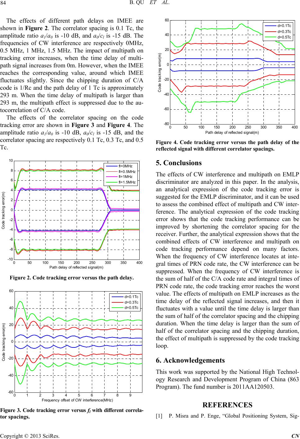 B. QU ET AL. 84 The effects of different path delays on IMEE are shown in Figure 2. The correlator spacing is 0.1 Tc, the amplitude ratio a1/a0 is -10 dB, and a0/cl is -15 dB. The frequencies of CW interference are respectively 0MHz, 0.5 MHz, 1 MHz, 1.5 MHz. The impact of multipath on tracking error increases, when the time delay of multi- path signal increases from 0m. However, when the IMEE reaches the corresponding value, around which IMEE fluctuates slightly. Since the chipping duration of C/A code is 1/Rc and the path delay of 1 Tc is approximately 293 m. When the time delay of multipath is larger than 293 m, the multipath effect is suppressed due to the au- tocorrelation of C/A code. The effects of the correlator spacing on the code tracking error are shown in Figure 3 and Figure 4. The amplitude ratio a1/a0 is -10 dB, a0/cl is -15 dB, and the correlator spacing are respectively 0.1 Tc, 0.3 Tc, and 0.5 Tc. 050100 150 200 250 300 350 400 -10 -8 -6 -4 -2 0 2 4 6 8 10 P at h del ay of reflected signal(m) Code t racking error(m) fl =0MH z fl =0.5MHz fl =1MH z fl =1.5MHz Figure 2. Code tracking error versus the path delay. 0123456789 -60 -40 -20 0 20 40 60 Frequency offset of CW in t erferenc e(M Hz ) Code t racking error(m) d=0.1Tc d=0.3Tc d=0.5Tc Figure 3. Code tracking error versus fl with different correla- tor spacings. 050100150200 250 300 350 400 -80 -60 -40 -20 0 20 40 60 Path delay of reflec ted signal(m) Code trac k ing error(m) d= 0.1Tc d= 0.3Tc d= 0.5Tc Figure 4. Code tracking error versus the path delay of the reflected signal with different correlator spacings. 5. Conclusions The effects of CW interference and multipath on EMLP discriminator are analyzed in this paper. In the analysis, an analytical expression of the code tracking error is suggested for the EMLP discriminator, and it can be used to assess the combined effect of multipath and CW inter- ference. The analytical expression of the code tracking error shows that the code tracking performance can be improved by shortening the correlator spacing for the receiver. Further, the analytical expression shows that the combined effects of CW interference and multipath on code tracking performance depend on many factors. When the frequency of CW interference locates at inte- gral times of PRN code rate, the CW interference can be suppressed. When the frequency of CW interference is the sum of half of the C/A code rate and integral times of PRN code rate, the code tracking error reaches the worst value. The effects of multipath on EMLP increases as the time delay of the reflected signal increases, and then it fluctuates with a value until the time delay is larger than the sum of half of the correlator spacing and the ch ipping duration. When the time delay is larger than the sum of half of the correlator spacing and the chipping duration, the effect of multipath is suppressed by the code tracking loop. 6. Acknowledgements This work was supported by the National High Technol- ogy Research and Development Program of China (863 Program). The fund number is 2011AA120503. REFERENCES [1] P. Misra and P. Enge, “Global Positioning System, Sig- Copyright © 2013 SciRes. CN 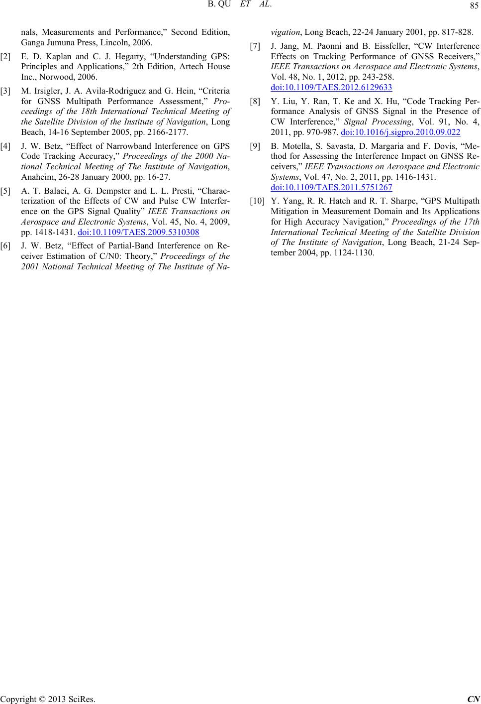 B. QU ET AL. Copyright © 2013 SciRes. CN 85 nals, Measurements and Performance,” Second Edition, Ganga Jumuna Press, Lincoln, 2006. [2] E. D. Kaplan and C. J. Hegarty, “Understanding GPS: Principles and Applications,” 2th Edition, Artech House Inc., Norwood, 2006. [3] M. Irsigler, J. A. Avila-Rodriguez and G. Hein, “Criteria for GNSS Multipath Performance Assessment,” Pro- ceedings of the 18th International Technical Meeting of the Satellite Division of the Institute of Navigation, Long Beach, 14-16 September 2005, pp. 2166-2177. [4] J. W. Betz, “Effect of Narrowband Interference on GPS Code Tracking Accuracy,” Proceedings of the 2000 Na- tional Technical Meeting of The Institute of Navigation, Anaheim, 26-28 January 2000, pp. 16-27. [5] A. T. Balaei, A. G. Dempster and L. L. Presti, “Charac- terization of the Effects of CW and Pulse CW Interfer- ence on the GPS Signal Quality” IEEE Transactions on Aerospace and Electronic Systems, Vol. 45, No. 4, 2009, pp. 1418-1431. doi:10.1109/TAES.2009.5310308 [6] J. W. Betz, “Effect of Partial-Band Interference on Re- ceiver Estimation of C/N0: Theory,” Proceedings of the 2001 National Technical Meeting of The Institute of Na- vigation, Long Beach, 22-24 January 2001, pp. 817-828. [7] J. Jang, M. Paonni and B. Eissfeller, “CW Interference Effects on Tracking Performance of GNSS Receivers,” IEEE Transactions on Aerospace and Electronic Systems, Vol. 48, No. 1, 2012, pp. 243-258. doi:10.1109/TAES.2012.6129633 [8] Y. Liu, Y. Ran, T. Ke and X. Hu, “Code Tracking Per- formance Analysis of GNSS Signal in the Presence of CW Interference,” Signal Processing, Vol. 91, No. 4, 2011, pp. 970-987. doi:10.1016/j.sigpro.2010.09.022 [9] B. Motella, S. Savasta, D. Margaria and F. Dovis, “Me- thod for Assessing the Interference Impact on GNSS Re- ceivers,” IEEE Transactions on Aerospace and Electronic Systems, Vol. 47, No. 2, 2011, pp. 1416-1431. doi:10.1109/TAES.2011.5751267 [10] Y. Yang, R. R. Hatch and R. T. Sharpe, “GPS Multipath Mitigation in Measurement Domain and Its Applications for High Accuracy Navigation,” Proceedings of the 17th International Technical Meeting of the Satellite Division of The Institute of Navigation, Long Beach, 21-24 Sep- tember 2004, pp. 1124-1130.
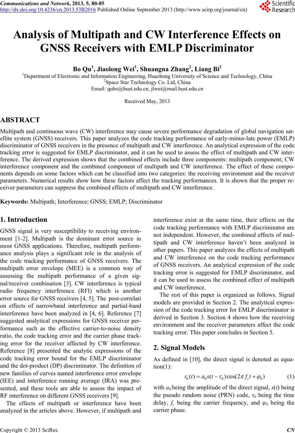
|