 Energy and Power Engineering, 2013, 5, 1259-1265 doi:10.4236/epe.2013.54B239 Published Online July 2013 (http://www.scirp.org/journal/epe) Pr otection Scheme Half Wavelength Tr ansmission Trunk Using Conventiona l Relay Renzo. G. Fabián1, Elson C. Gomes1, Maria C. Tavares1, Carlos A. Floriano2 1School of Electrical and Computing Engineering, University of Campinas, Campinas, Brazil 2ELETRONORTE -Brasília, Brazil Email: cristina@dsce.fee.unicamp.br, carlos.floriano@eletronorte.gov.br Received April, 2013 ABSTRACT This paper presents the main results on the use of conventional protection hardware to protect a Half Wavelength Transmission Line, or shortly AC-Link, for possible occurrence of three-phase and single-phase fault during energiza- tion maneuver. Lines of these dimensions do not exist today, but in countries of continental size they could be an inter- esting alternative to HVDC transmission, since the AC-Link has less dependence on Power Electronics technology. The studies on performance and relay settings were implemented using the RTDS real-time simulator. It is important to note that the AC-Link protection for the energization maneuver can be performed with existing hardware on conventional relays. Keywords: Protection; Half Wavelength Transmission; AC-Link, RTDS; Digital Relays 1. Introduction Countries with continental extensions such as Brazil, China and Russia are faced with the need to transport large blocks of energy over long distances, namely above 2000 km. The use of transmission lines with a little more than a half wavelength is an important alternative that must be properly considered. Currently, these long transmission trunks are made by high-voltage direct current transmission lines (HVDC), but an alternating current (AC) alternative with some particular characteristics might be the most economical one, having much less dependence on the Power Elec- tronics Technology. In the 1960s, the first studies were done showing that the AC line has an interesting behavior in terms of volt- age, current and stability of the system when it has elec- trical length a little more than half the length of the elec- tromagnetic wave [1-3]. Nowadays new researches have been studying this alternative, as [4-12]. In a 60 Hz power system the length of the transmission trunk is approximately 2600 km [4, 6]. The half wave- length lines exhibit behavior very similar to short lines in steady state and are more robust during transients. This is an alternative to the HVDC line, because the AC-Link may present a cost of implementation up to 20% lower [6, 7]. As there is not a half-wavelength transmission line in the world, Brazilian Electrical Energy Agency (ANEEL) proposed to carry out an energization test connecting in series sections of existing lines in the Brazilian intercon- nected system [8-11]. This test will allow the analysis of the behavior of the AC-Link and the comparison with the studies made so far. The energization test needs a protection system, and it is necessary to analyze whether the current existing re- lays could protect against possible faults along the line. Otherwise, a more efficient protection scheme should be proposed. The results of the study on the protection for three- phase and single-phase faults using the relays available in substations are presented. The studies were performed using the RTDS real-time simulator together with the same relays available on-site. The analysis to identify the relays settings are presented in the following sections, as well as the results of the protection system proposed and the main conclusions. 2. Analyzed System Description The used transmission system is based on the lines of 500 kV that can form an AC-Link with 2600 km long. These lines are the interconnections North-South I and North-South II that are parallel with a distance of 60 m between towers, and part of the interconnection North East-South East, as seen in Figure 1 [8,9]. The AC-Link will be energized at shot through the breaker of Serra da Mesa I substation. Copyright © 2013 SciRes. EPE  R. G. FABIÁN ET AL. 1260 The lines that will compose the AC-Link Test are of the same voltage level, but they are not equal. Tables 1 and 2 present the series and shunt parameters per unit length in sequence components. The lines were supposed ideally transposed lines and the parameters were calcu- lated for 60 Hz. Traditional soil representation was applied during the tests, specifically the soil resistively was considered con- stant with frequency over the entire length of the AC-Link trunk with value of 4000 .m due to high soil resistively in these regions [13]. North -South 1 Trunk ⇒ – 256 km255 km173 km330 km 500 kV500 kV500 kV500 kV500 kV 500 kV500 kV500 kV500 kV500 kV Serra da Mesa 1 SM1 Gurupi 1 GU1 Miracema 1 MI1 Colinas 1 CO1 Imperatriz IMP North -South2 Trunk ⇐ 256 km255 km173 km330 km Serra da Mesa 2 SM2 Gurupi 2 GU2 Miracema 2 MI2 Colinas 2 CO2 Imperatriz IMP NorthEast -SouthEast Trunk ⇒ 251.3 km321.3 km 500 kV500 kV500 kV Serra da Mesa SM Rio das Eguas RDE Bom Jesus da Lapa BJL Legend Switching breaker Breaker always close Breaker always open ⇒Assumed trunk connection for the test Figure 1. Single-phase diagram of AC-Link Test - 500 kV. Table 1. Positive/negative sequences longitudinal and transversal parameters calculated at 60 Hz. Line Unitary Resistance [/km] Unitary Inductance [mH/km] Unitary Capacitance [F/km] North-South I 0.01589 0.70700 0.01612 North-South II 0.01602 0.71089 0.01634 North East-South East 0.01602 0.72403 0.01603 Table 2. Zero sequence longitudinal and transversal pa- rameters calculated at 60 Hz - North-South II. Line Unitary Re- sistance [/km] Unitary Inductance [mH/km] Unitary Capacitance [F/km] North-South I 0.37138 4.11662 0.00725 North-South II 0.34822 3.74452 0.00946 North East-South East 0.34821 3.75767 0.00934 2.1. Protection System In the protection study for the AC-Link energization maneuver, it was initially observed the behavior of the variables: voltage, current and impedance for three-phase and single-phase faults along the transmission line. Ini- tially, it was studied the existent distance protection and later other additional functions of the relay SEL 321-1. The faults were represented as impedance at the site of defect of 20 . The system simulated in the RTDS is shown in Figure 1 and there were monitored the voltages in the buses and the currents in the circuit-breakers (CB), as well as the magnitudes measured by instruments transformers (CT and PT). The CTs ratio was 3000:1 and the PTs ratio was 4500:1. Formerly only the relay from the substation Serra da Mesa 1, SEL-321-1, was used. 3. Three-phase Faults Protection 3.1. Using Conventional Distance Protection In this section the distance protection was analyzed to see if it would be suitable for the energization manouver test of the AC-Link. To calculate the impedances, a compo- nent was programmed for RTDS in the Standard C lan- guage using the CBuilder tool of RSCAD. The compo- nent was programmed according to [14]. In certain locations of the line, faults reach quasi reso- nance conditions, either of positive (for three-phase faults) or zero (for single-phase faults) sequence, rising the voltages and currents along the AC-Link. In the case of grounded and isolated three-phase faults, for faults occurring in the region between 65% and 90% from the AC-Link measured from the sending terminal, the posi- tive sequence quasi-resonance condition becomes critical, with rapid increases in voltage at the terminals of the breaker and high currents. This critical region depends on the terminal systems interaction with the AC-Link. In the present case the AC-Link is supposed isolated, connected to sending end substation (SE). It is important to emphasize that during three-phase faults at critical location the voltage along the line will grow to a limit when insulation level will be reached and flashover will occur along the line. In [12] it was pro- posed the use of a reduced isolation distance (RID) posi- tioned at approximately 40% of the total length of the line from the SE to quickly remove the AC-Link Test from the quasi-resonance condition. This RID mitigation method consists in adjusting the number of insulators in order to provoke the flashover for overvoltages higher than 1.6 p.u. In that location the overvoltages will not be higher than 1.2 p.u. during energization transient and therefore RID will not operate during the energization maneuver without defect. However, if a severe condition appears RID will actuate immediately, removing the Copyright © 2013 SciRes. EPE  R. G. FABIÁN ET AL. 1261 Link from the quasi-resonance condition. Figure 2 shows the impedances calculated from the voltages and currents of the PTs and CTs from Serra da Mesa 1, for faults applied along the line (at intervals of 10% of the length of each line section). Each point on the graph indicates the place of fault applied. In this graph, it was supposed that the insulator string of the Imperatriz substation had a normal length, i.e. they were not re- duced. The squares are the impedances at the energiza- tion steady state of the AC-Link without the occurrence of fault. As the maximum impedance that the relay SEL 321-1 can identify is 320 , it can be verified that the relay could only protect the section of Serra da Mesa 1 (SM1 - km 0) up to the area near the Imperatriz (IMP - km 1040) substation. However, the reverse protection zones can be used to protect the section from Bom Jesus da Lapa (BJL - km 2601) up to the area near Miracema 2 (MI2 - km 1517). The no fault steady state impedances should be dealt properly (squares), as these points are close to the impedances for faults that occur near line center. The distance protection cannot cover the section be- tween Imperatriz and Colinas 2 (central region) and that it is necessary to block the distance protection trip for faults near Colinas 2. The RID in a tower near the Imperatriz substation will modify the distance protection performance for faults near the remote end. RID starts working for faults that affect the Link from the Gurupi 2 (GU2 - km 1772) sub- station toward the remote terminal. The impedance changes drastically for fault between Colinas 2 and Gu- rupi 2, specifically the upstream and downstream of the first location where the RID acts. Figure 2. Impedances seen at Serra da Mesa 1, without RID in Imperatriz. 3.2. Additional Protection Functions From the above, the existing distance protection can pro- tect the line in its initial and final sections through the forward and reverse zone. It can indeed be used two for- ward zones and two reverse zones, with Zone 1 forward with instant action, Zone 2 forward with delayed action, Zone 3 reverse with instant action and Zone 4 reverse with delayed action. This makes it possible to identify the fault site, as the zone would indicate the section of the line where the fault occurred. However, the distance protection of the relay SEL 321-1 would not be capable of protecting the entire line during the energization test in the event of three phase faults in the central region of the line. Alternatives were analyzed to obtain a more efficient protection scheme. As the faults are three-phase faults, the components of zero and negative sequence will only appear during fault transient and they are of low magni- tude. In Figure 3 the voltages and currents in the primary and secondary sides of the PTs and CTs are presented for the occurrence of three-phase to ground fault along the entire line. The maximum voltage for energization is 567.05 kV and voltage at operation without fault is 286.76 kVrms. It can be observed that for faults in SM 1 voltage is reduced to close to zero, then, as the fault moves away from the generator terminal, voltage at SM1 increases, which is the expected behavior for a conven- tional line. However, for faults near the middle of the t Figure 3. Voltages and currents at sending end for tree- phase faults along the line. a) Voltage in primary side of PT. b) Voltage in secondary side of PT. c) Current in primary side of CT. d) Current in secondary side of CT. Copyright © 2013 SciRes. EPE  R. G. FABIÁN ET AL. 1262 line, the voltage at SM1 exceeds the voltage of the steady state without fault, which is the characteristic behavior of he AC-Link. As the fault location moves toward the open terminal, the voltages at SM1 reach maximum for faults near Serra da Mesa 2 (SM2) and then decrease as the fault moves to Bom Jesus da Lapa (BJL). The current on the primary side of the CT reaches 1765 A (peak) on energization and has a current of 285 Arms in the operation without fault. It can be veri- fied that for faults near SM1, the current measured is quite high when compared to the current value without fault. As the fault moves toward the open terminal the current decreases, but is still higher than the current from the operation without fault. This would be an expected behavior in conventional lines; however, for faults lo- cated near the middle of the line, the current in SM1 be- comes lower than the current from the operation without fault. This is a characteristic of the AC-Link. After reaching its lowest value, the current begins to increase as the fault moves to the remote terminal, peak- ing near SM2 and finally begins to decrease as the fault continues to move to the remote end. The high currents measured for faults near Serra da Mesa 2 are similar to those obtained for terminal faults, a characteristic behav- ior of the AC-Link that is different from a line with con- ventional length. Analyzing the voltages and currents, it can be ob- served situations characteristics of an AC-Link, mainly in the region corresponding to faults near the middle of the line. It can be seen that it is possible to use Under- voltage, Overvoltage and Overcurrent devices to identify three-phase faults along the AC-Link, but there are still problems of selectivity for faults that occur near the mid- dle of the line. Figure 4 shows the voltages in all buses for three-phase fault at Colinas 2. In Figure 4 it can be verified that voltages hardly suf- fer variation in the substations at the upstream of the fault location. The currents at the fault location do not suffer variation. This explains the difficulty in identify- ing these faults. 3.3. Additional Settings for the Relay SEL 321-1 With the above considerations, it was analyzed the pos- sibility of additional settings in order to complement the distance protection trying to protect the entire line for three-phase faults. Initially, it was used the distance protection (21) of the relay as it is more selective. It was necessary to consider the operation impedance without fault to block the dis- tance protection using the Load Encroachment. Some additional devices were used, as described be- low: Undervoltage Device (27L): was set at 0.8 p.u., timed in 5 cycles. The 27L device was adjusted with the loss of potential device (LOP), and the final logical was: 27L*! LOP. The performance of the relay would improve significantly if it were used the state of the breaker to- gether with the 27L device, in place of the LOP device; Overvoltage Device (59N): was set at 1.2 p.u., timed in 12 cycles. Overcurrent Device (51P): pick-up value of 0.5; family of curve: U3; and time dial: 2. Figure 4. Voltages in all buses for fault at Colinas 2. Copyright © 2013 SciRes. EPE  R. G. FABIÁN ET AL. 1263 3.4. Tests Performed and Results To verify the protection performance in the electrical system, the simulations were performed with RTDS, ge- nerating signals of voltages and currents that were ampli- fied and finally injected into the relay SEL 321-1. The relay trip was injected back into RTDS. The three-phase-to-ground faults have been applied along the entire line, initially every 20% of the length of each section, to allow observing the performance of each protective device. Finally all the devices were tested si- multaneously for faults every 10% of the length of each section. The distance protection operates for faults that occur in the first 948 km and in the last 828.8 km of AC-Link. The RID starts to operate from kilometer 1772, which corresponds to the Gurupi 2 substation. The distance re- lay operates at 1721 km from Serra da Mesa 1, and after that the distance protection does not operate for a 308 km section due to the operation of RID, returning to operate in the last 572.6 km from the AC-Link. The central sec- tion of 480.5 km is not protected. Finally a relay located in Serra da Mesa 2 was consid- ered. For this relay, the Undervoltage device (27L) is used. It can be observed that it suitably covers the central region and it does not operate for faults at the beginning of the AC-link because the Undervoltage device (27L) was adjusted to act together with the negative (!) of the loss of potential device (LOP), and the Trip logic is: 27L*!LOP. The relay performance can be improved using the state of the breaker instead of the LOP device in the trip logic for Undervoltage. 4. Single-phase Faults Protection The phase current and voltage characteristics were ob- served at the sending end considering the application of single-phase faults every 20 km along the line. Beside the peak values, the faults were applied for 700 ms in order to observe its steady state, as presented in Figure 5. Faults in central region of the line provide voltages and currents values similar or even lower than the ones seen with the system in steady state. This characteristic does not allow to distinguish a single-phase fault from a no load case. Moreover, the behavior of voltages and currents are not monotonic, which increase the problem of identification to the fault location. There were obtained current and voltage curves of se- quence components observed also in the sending end, searching for a situation in which the single-phase fault is clearly observed, Figure 6. These curves permit the es- tablishment of limits for each voltages and currents se- quence observed at sending end, together with the case for no load condition. 4.1. Adjustments of Digital Relay AC-Link the distance protection functions are not suffi- cient to protect the AC-Link. Other relay functions have to be used to provide an efficient protection in the case of a single-phase fault. In Figure 7 some functions and the protected areas obtained with RTDS simulations are showed. Faults in the central region of the line behave as high impedance, producing little variation in the voltages and currents seen as phases or sequences components at line SE, as shown in Figure 8. Function 59N (zero sequence overvoltage) properly identified central region faults. Figure 5. Peak values of current and voltages in phase components at sending end for single-phase faults applied along the AC-Link. Figure 6. Zero se que nc e component phase to ground voltage of at SE - peak values (V0P) and sustained (V0S) for sin- gle-phase faults along the AC-Link. Figure 7. Single-phase fault protection. Copyright © 2013 SciRes. EPE 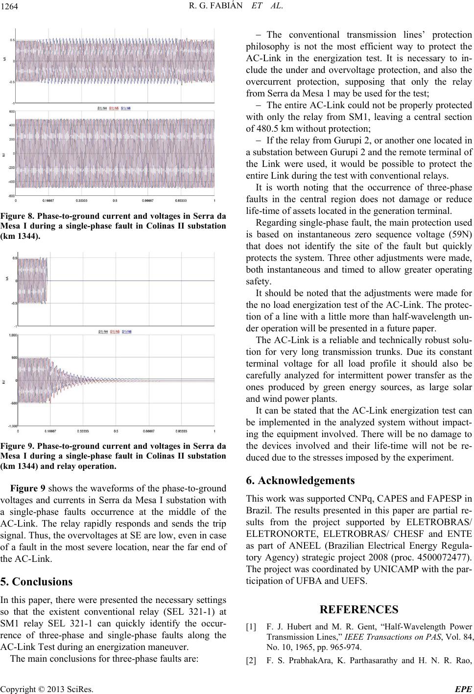 R. G. FABIÁN ET AL. 1264 Figure 8. Phase-to-ground current and voltages in Serra da Mesa I during a single-phase fault in Colinas II substation (km 1344). Figure 9. Phase-to-ground current and voltages in Serra da Mesa I during a single-phase fault in Colinas II substation (km 1344) and relay operation. Figure 9 shows the waveforms of the phase-to-ground voltages and currents in Serra da Mesa I substation with a single-phase faults occurrence at the middle of the AC-Link. The relay rapidly responds and sends the trip signal. Thus, the overvoltages at SE are low, even in case of a fault in the most severe location, near the far end of the AC-Link. 5. Conclusions In this paper, there were presented the necessary settings so that the existent conventional relay (SEL 321-1) at SM1 relay SEL 321-1 can quickly identify the occur- rence of three-phase and single-phase faults along the AC-Link Test during an energization maneuver. The main conclusions for three-phase faults are: The conventional transmission lines’ protection philosophy is not the most efficient way to protect the AC-Link in the energization test. It is necessary to in- clude the under and overvoltage protection, and also the overcurrent protection, supposing that only the relay from Serra da Mesa 1 may be used for the test; The entire AC-Link could not be properly protected with only the relay from SM1, leaving a central section of 480.5 km without protection; If the relay from Gurupi 2, or another one located in a substation between Gurupi 2 and the remote terminal of the Link were used, it would be possible to protect the entire Link during the test with conventional relays. It is worth noting that the occurrence of three-phase faults in the central region does not damage or reduce life-time of assets located in the generation terminal. Regarding single-phase fault, the main protection used is based on instantaneous zero sequence voltage (59N) that does not identify the site of the fault but quickly protects the system. Three other adjustments were made, both instantaneous and timed to allow greater operating safety. It should be noted that the adjustments were made for the no load energization test of the AC-Link. The protec- tion of a line with a little more than half-wavelength un- der operation will be presented in a future paper. The AC-Link is a reliable and technically robust solu- tion for very long transmission trunks. Due its constant terminal voltage for all load profile it should also be carefully analyzed for intermittent power transfer as the ones produced by green energy sources, as large solar and wind power plants. It can be stated that the AC-Link energization test can be implemented in the analyzed system without impact- ing the equipment involved. There will be no damage to the devices involved and their life-time will not be re- duced due to the stresses imposed by the experiment. 6. Acknowledgements This work was supported CNPq, CAPES and FAPESP in Brazil. The results presented in this paper are partial re- sults from the project supported by ELETROBRAS/ ELETRONORTE, ELETROBRAS/ CHESF and ENTE as part of ANEEL (Brazilian Electrical Energy Regula- tory Agency) strategic project 2008 (proc. 4500072477). The project was coordinated by UNICAMP with the par- ticipation of UFBA and UEFS. REFERENCES [1] F. J. Hubert and M. R. Gent, “Half-Wavelength Power Transmission Lines,” IEEE Transactions on PAS, Vol. 84, No. 10, 1965, pp. 965-974. [2] F. S. PrabhakAra, K. Parthasarathy and H. N. R. Rao, Copyright © 2013 SciRes. EPE 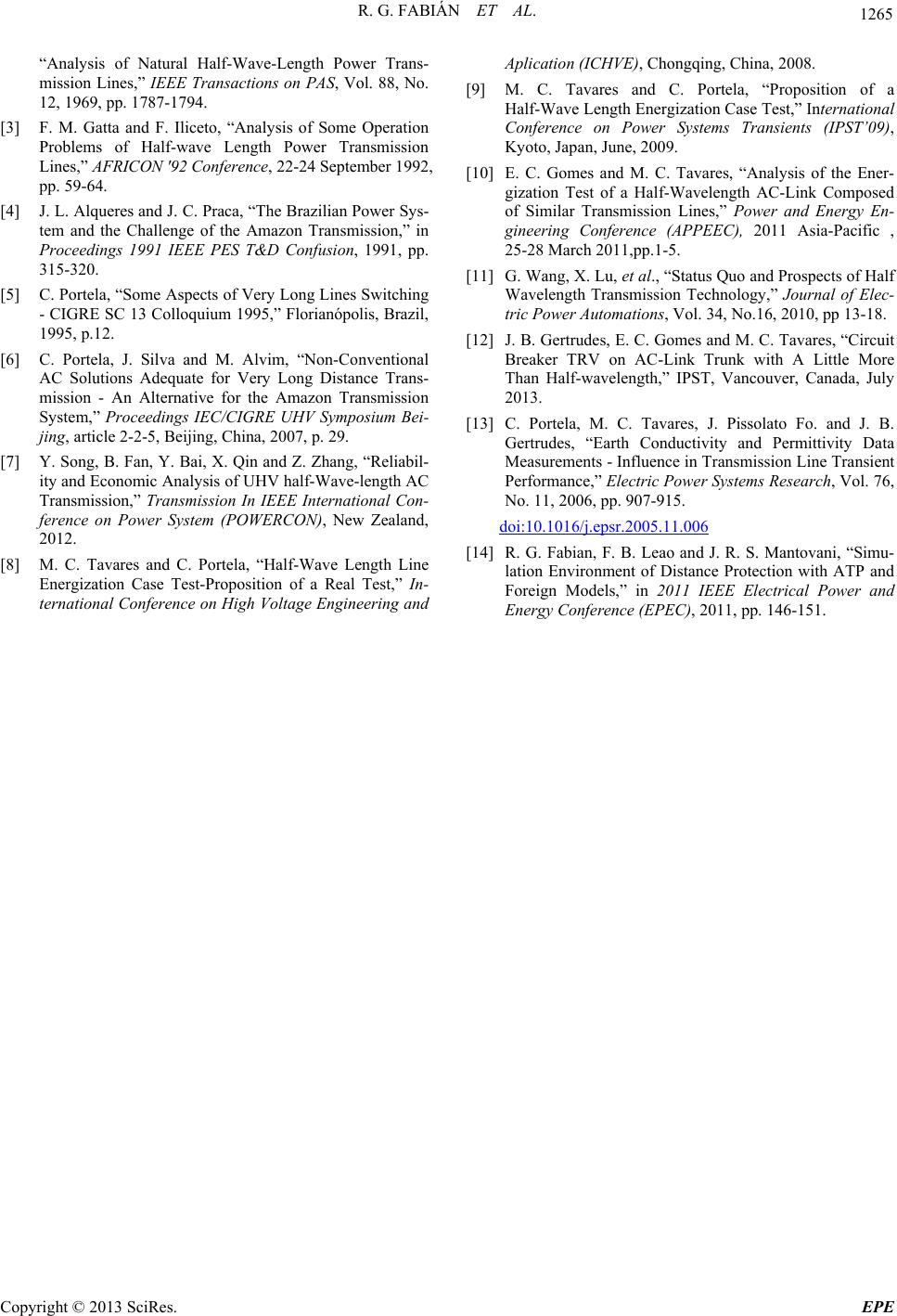 R. G. FABIÁN ET AL. Copyright © 2013 SciRes. EPE 1265 “Analysis of Natural Half-Wave-Length Power Trans- mission Lines,” IEEE Transactions on PAS, Vol. 88, No. 12, 1969, pp. 1787-1794. [3] F. M. Gatta and F. Iliceto, “Analysis of Some Operation Problems of Half-wave Length Power Transmission Lines,” AFRICON '92 Conference, 22-24 September 1992, pp. 59-64. [4] J. L. Alqueres and J. C. Praca, “The Brazilian Power Sys- tem and the Challenge of the Amazon Transmission,” in Proceedings 1991 IEEE PES T&D Confusion, 1991, pp. 315-320. [5] C. Portela, “Some Aspects of Very Long Lines Switching - CIGRE SC 13 Colloquium 1995,” Florianópolis, Brazil, 1995, p.12. [6] C. Portela, J. Silva and M. Alvim, “Non-Conventional AC Solutions Adequate for Very Long Distance Trans- mission - An Alternative for the Amazon Transmission System,” Proceedings IEC/CIGRE UHV Symposium Bei- jing, article 2-2-5, Beijing, China, 2007, p. 29. [7] Y. Song, B. Fan, Y. Bai, X. Qin and Z. Zhang, “Reliabil- ity and Economic Analysis of UHV half-Wave-length AC Transmission,” Transmission In IEEE International Con- ference on Power System (POWERCON), New Zealand, 2012. [8] M. C. Tavares and C. Portela, “Half-Wave Length Line Energization Case Test-Proposition of a Real Test,” In- ternational Conference on High Voltage Engineering and Aplication (ICHVE), Chongqing, China, 2008. [9] M. C. Tavares and C. Portela, “Proposition of a Half-Wave Length Energization Case Test,” International Conference on Power Systems Transients (IPST’09), Kyoto, Japan, June, 2009. [10] E. C. Gomes and M. C. Tavares, “Analysis of the Ener- gization Test of a Half-Wavelength AC-Link Composed of Similar Transmission Lines,” Power and Energy En- gineering Conference (APPEEC), 2011 Asia-Pacific , 25-28 March 2011,pp.1-5. [11] G. Wang, X. Lu, et al., “Status Quo and Prospects of Half Wavelength Transmission Technology,” Journal of Elec- tric Power Automations, Vol. 34, No.16, 2010, pp 13-18. [12] J. B. Gertrudes, E. C. Gomes and M. C. Tavares, “Circuit Breaker TRV on AC-Link Trunk with A Little More Than Half-wavelength,” IPST, Vancouver, Canada, July 2013. [13] C. Portela, M. C. Tavares, J. Pissolato Fo. and J. B. Gertrudes, “Earth Conductivity and Permittivity Data Measurements - Influence in Transmission Line Transient Performance,” Electric Power Systems Research, Vol. 76, No. 11, 2006, pp. 907-915. doi:10.1016/j.epsr.2005.11.006 [14] R. G. Fabian, F. B. Leao and J. R. S. Mantovani, “Simu- lation Environment of Distance Protection with ATP and Foreign Models,” in 2011 IEEE Electrical Power and Energy Conference (EPEC), 2011, pp. 146-151.
|