Journal of Materials Science and Chemical Engineering, 2013, 1, 16-22
http://dx.doi.org/10.4236/msce.2013.15004 Published Online October 2013 (http://www.scirp.org/journal/msce)
Copyright © 2013 SciRes. MSCE
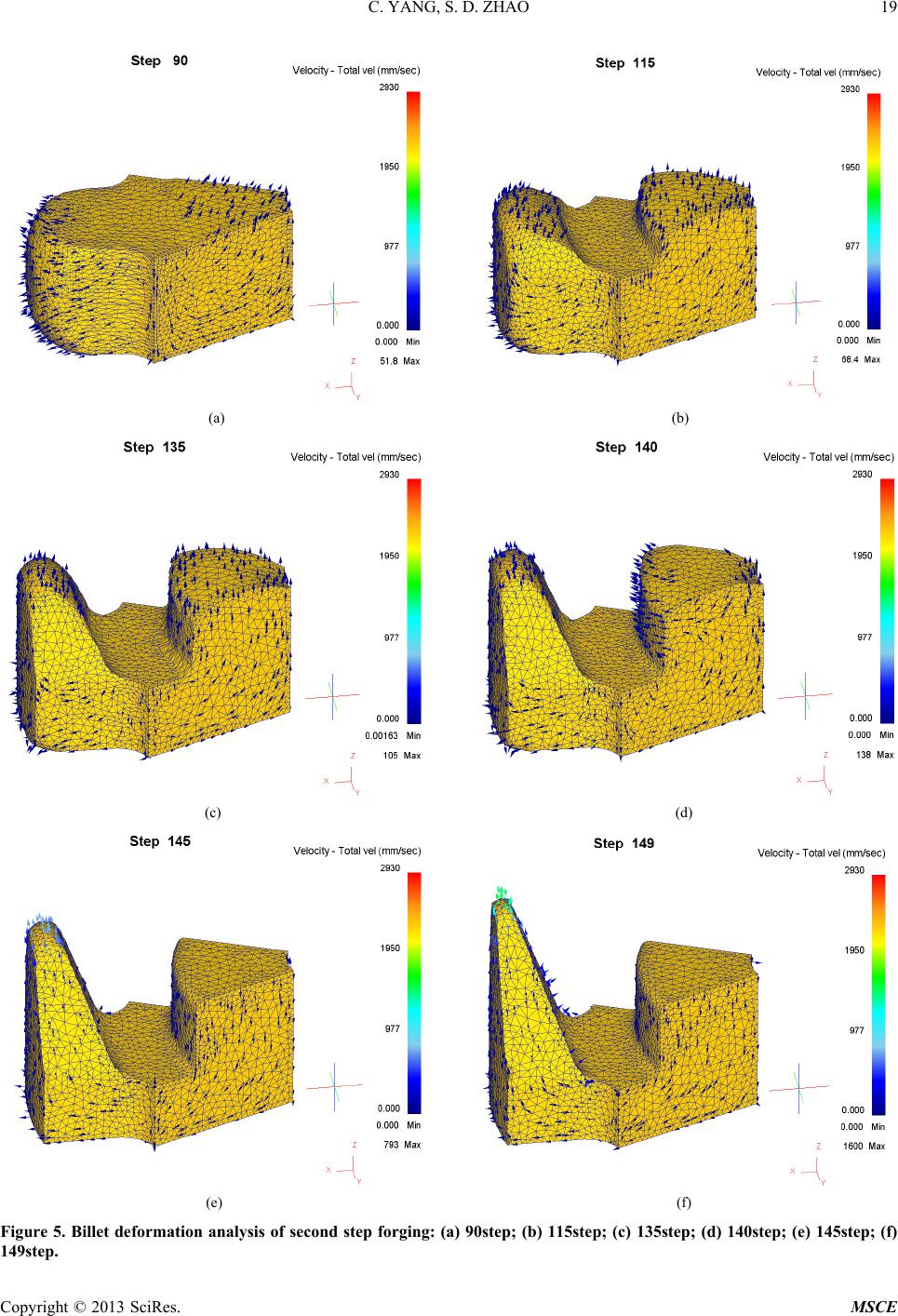
Research on Combi ned Hot Extrusion Forming Process
of Alternator Poles
Cheng Yang1 ,2, Shengdun Zhao1
1School of Mechanical Engineering, Xi’an Jiaotong University, Xi’an, China
2School of Metallurgical Engineering, Xi’an University of Architecture and Technology, Xi’an, China
Email: ya ng.cheng@stu.xjt u.edu.cn, sdzhao@mail.xjtu.edu.cn
Received July 2013
ABSTRACT
Based on the structure analysis of alternator poles, two closed die forging steps in one heat forming process of alternator
poles were put forward, as well as the forming die system. Firstly, a thicker bottom base of alternator poles was per-
formed by radial forging, then the middle boss and pole claw were forming on the bottom base by backward extrusion.
A 3-D coupled thermo-mechanical finite element model was created. The billet deformation, metal flow and forming
load were obtained. The results showed that a filling well forging without overlap defects could be obtained by this
process, and that the forming load at the first step increased slowly, but the load increased sharply at the second step
when the middle boss was filling completely by the former process. An improved process was put forward, which
changed the flow mode in the second forging step; it can considerably reduce the final forgi n g load.
Keywords: Radial Forging; Backward Extrusion; Alternator Poles; Closed Die Forging
1. Introduction
According to the statistics of china association of auto-
mobile manufactures, in china the yield and sales of au-
tomobile were 19.27 million and 19.3 million respec-
tively in 2012, both had reached all time high. Alternator
poles are used in pairs in modern car generators, along
with the rapid growth of the auto industry; they need to
be produced in large amounts. Usually they are produced
with varying cold, warm or hot forging processes [1-8].
There are from five to nine single forging stages. A typi-
cal hot forging process includes two pre-forming opera-
tions combined with forming, trimming and sizing. Cold
forging is done with forward extrusion, setting, heading,
piercing, trimming (on separate machines), bending and
sizing operatio ns . Wa rm forgi ng is based on lateral extru-
sion, followed by heading, trimming, cupping, bending,
piercing and sizing. All the processes in use have some
shortcomings, such as high cost and inefficient. There-
fore, analyzing the forming law, improving forming me-
thod and decreasing forming cost have been problems
urgent to be solved.
Precision closed die forging has the advantages such
as reasonable tissue flow direction, good surface, no
flash, no trimming process and intrinsic performance,
which lead to material saving, better mechanical proper-
ties and higher productivity etc. Based on the structure
analysis of alternator poles, two closed die forging steps
in one heat of alternator poles forming process was put
forward, as well as the forming die system. A 3-D cou-
pled thermo-mechanical finite element model was cre-
ated, which was analyzed by the software DEFORM-3D.
The billet deformation, metal flow and forming load
were obtained. The results showed that a filling well
forging without overlap defects could be obtained by this
process, and that the forming load could considerably
reduced by the im pr o ve d process .
2. Process and Die Design of Two Closed Die
Forging Steps in One Heat of Alternator
Poles
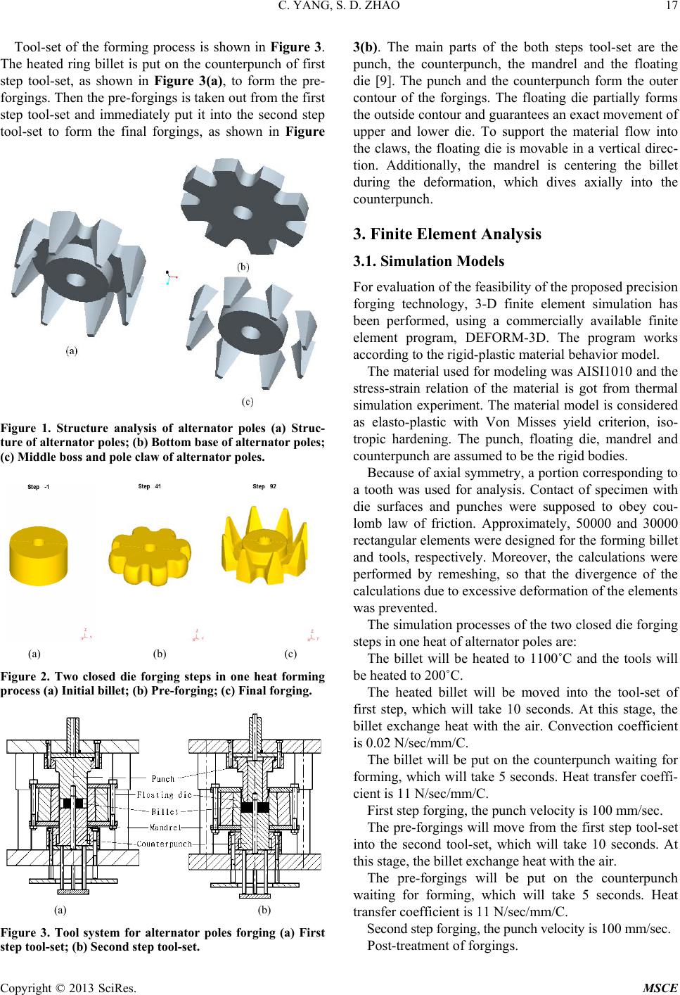
The structure of alternator pole, as shown in Figure 1(a),
is axial symmetry. It can be divided into bottom base,
middle boss and pole claw, as shown in Figure 1(b) and
Figure 1(c), respectively. The bottom base, which looks
like a gear, can be formed by radial forging. The middle
boss and pole claw can be formed by forward extrusion
or backward extrusion.
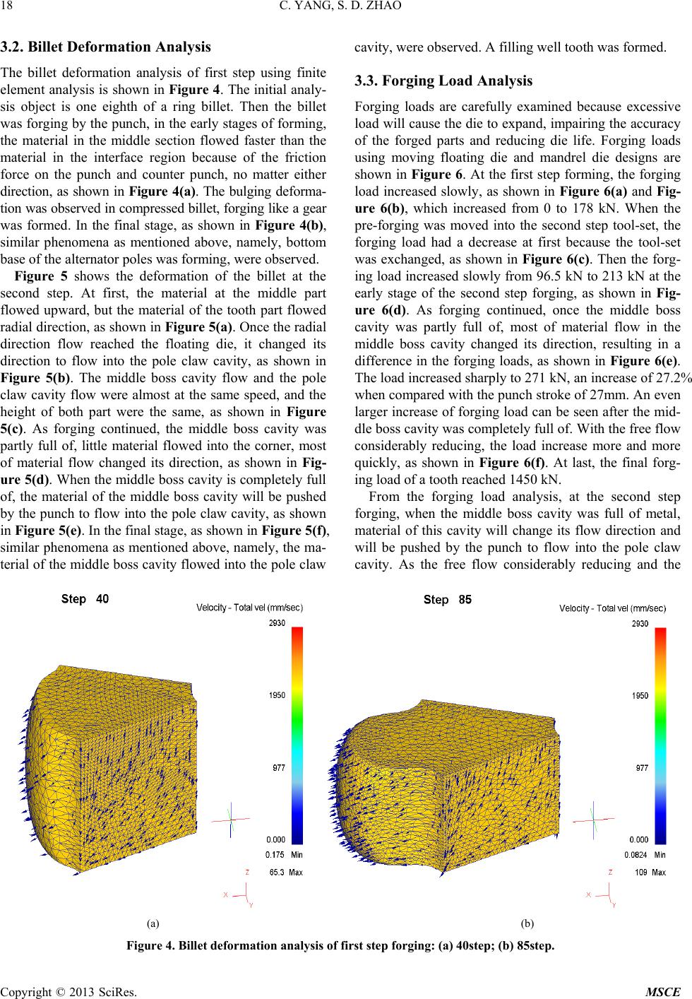
Based on the structure analysis, a new forming process
was put forward. Firstly, a thicker bottom base, as shown
in Figure 2(b), was formed by radial forging on ring
billet, as shown in Figure 2(a), and secondly the middle
boss and pole claws, as shown in Figure 2( c), were
formed by backward extrusion on the thicker bottom
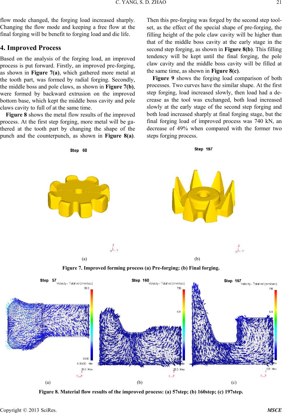
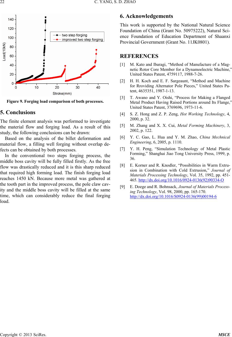
base.
C. YANG, S. D. ZHAO
Copyright © 2013 SciRes. MSCE
17
Tool-set of the forming process is shown in Figure 3.
The heated ring billet is put on the counterpunch of first
step tool-set, as shown in Figure 3(a), to form the pre-
forgings. Then the pre-forgings is taken out from the first
step tool-set and immediately put it into the second step
tool-set to form the final forgings, as shown in Figure
Figure 1. Structure analysis of alternator poles (a) Struc-
ture of alternator poles; (b) Bottom base of alternator poles;
(c) Middle boss and pole claw of alternator poles.
(a) (b) (c)
Figure 2. Two closed die forging steps in one heat forming
process (a) Initial billet; (b) Pre-forging; (c) Final forging.
(a) (b)
Figure 3. Tool system for alternator poles forging (a) First
step tool-set; (b) Second step tool-set.
3(b). The main parts of the both steps tool-set are the
punch, the counterpunch, the mandrel and the floating
die [9]. The punch and the counterpunch form the outer
contour of the forgings. The floating die partially forms
the outside contour and guarantees an exact movement of
upper and lower die. To support the material flow into
the claws, the floating die is movable in a vertical direc-
tion. Additionally, the mandrel is centering the billet
during the deformation, which dives axially into the
counterpunch.
3. Finite Element Analysis
3.1. Simulation Models
For evaluation of the feasibility of the proposed precision
forging technology, 3-D finite element simulation has
been performed, using a commercially available finite
element program, DEFORM-3D. The program works
according to the rigid-plastic material behavior model.
The material used for modeling was AISI1010 and the
stress-strain relation of the material is got from thermal
simulation experiment. The material model is considered
as elasto-plastic with Von Misses yield criterion, iso-
tropic hardening. The punch, floating die, mandrel and
counterpunch are assumed to be the rigid bodies.
Because of axial symmetry, a portion correspond ing to
a tooth was used for analysis. Contact of specimen with
die surfaces and punches were supposed to obey cou-
lomb law of friction. Approximately, 50000 and 30000
rectangular elements were designed for the forming billet
and tools, respectively. Moreover, the calculations were
performed by remeshing, so that the divergence of the
calculations due to excessive deformation of the elements
was prevented.
The simulation processes of the two closed die forging
steps in one heat of alternator poles are:
The billet will be heated to 1100˚C and the tools will
be heated to 200˚C.
The heated billet will be moved into the tool-set of
first step, which will take 10 seconds. At this stage, the
billet exchange heat with the air. Convection coefficient
is 0.02 N/sec/mm/C.
The billet will be put on the counterpunch waiting for
forming, which will take 5 seco nds. Heat transfer coeffi-
cient is 11 N/sec/mm/C.
First step forging, the punc h ve locity is 100 mm/sec.
The pre-forgings will move from the first step tool-set
into the second tool-set, which will take 10 seconds. At
this stage, the billet exchange heat with the air.
The pre-forgings will be put on the counterpunch
waiting for forming, which will take 5 seconds. Heat
transfer coefficient is 11 N/sec/mm/C.
Second step f orging, the punch velocity is 100 mm/sec.
Post-treatment of forgings.
C. YANG, S. D. ZHAO
Copyright © 2013 SciRes. MSCE
18
3.2. Billet Deformation Analysis
The billet deformation analysis of first step using finite
element analysis is sho wn in Figure 4. The initial analy-
sis object is one eighth of a ring billet. Then the billet
was forging by the punch, in the early stages of forming,
the material in the middle section flowed faster than the
material in the interface region because of the friction
force on the punch and counter punch, no matter either
direction, as shown in Figure 4(a). The bulging deforma-
tion was observed in compressed billet, forging like a gear
was formed. In the final stage, as shown in Figure 4(b),
similar phenomena as mentioned above, namely, bottom
base of the alternator poles was forming, were observed.
Figure 5 shows the deformation of the billet at the
second step. At first, the material at the middle part
flowed upward, but the material of the tooth part flowed
radial direction, as shown in Figure 5(a). Once the radial
direction flow reached the floating die, it changed its
direction to flow into the pole claw cavity, as shown in
Figure 5(b). The middle boss cavity flow and the pole
claw cavity flow were almost at the same speed, and the
height of both part were the same, as shown in Figure
5(c). As forging continued, the middle boss cavity was
partly full of, little material flowed into the corner, most
of material flow changed its direction, as shown in Fig-
ure 5(d). When the middle boss cavity is completely full
of, the material of the middle boss cavity will be pushed
by the punch to flow into the pole claw cavity, as shown
in Figu re 5(e). In the final stage, as shown in Figure 5(f),
similar phenomena as mentioned above, namely, the ma-
terial of the middle boss cavity flowed into the pole claw
cavity, were observed. A filling wel l tooth w a s formed.
3.3. Forging Load Analysis
Forging loads are carefully examined because excessive
load will cause the die to expand, impairing the accuracy
of the forged parts and reducing die life. Forging loads
using moving floating die and mandrel die designs are
shown in Figure 6. At the first step forming, the forging
load increased slowly, as shown in Figure 6(a) and Fig-
ure 6(b), which increased from 0 to 178 kN. When the
pre-forging was moved into the second step tool-set, the
forging load had a decrease at first because the tool-set
was exchanged, as shown in Figure 6(c). Then the forg-
ing load increased slowly from 96.5 kN to 213 kN at the
early stage of the second step forging, as shown in Fig-
ure 6(d). As forging continued, once the middle boss
cavity was partly full of, most of material flow in the
middle boss cavity changed its direction, resulting in a
difference in the forging loads, as shown in Figure 6(e).
The load increased sharply to 271 kN, an increase of 27.2%
when compared with the punch stroke of 27mm. An even
larger increase of forging load can be seen after the mid-
dle boss cavity was completely full of . With the free flow
considerably reducing, the load increase more and more
quickly, as shown in Figure 6(f). At last, the final forg-
ing load of a tooth reached 1450 kN.
From the forging load analysis, at the second step
forging, when the middle boss cavity was full of metal,
material of this cavity will change its flow direction and
will be pushed by the punch to flow into the pole claw
cavity. As the free flow considerably reducing and the
(a) (b)
Figure 4. Billet deformation analysis of first step forging: (a) 40step; (b) 85step.
C. YANG, S. D. ZHAO
Copyright © 2013 SciRes. MSCE
19
(a) (b)
(c) (d)
(e) (f)
Figure 5. Billet deformation analysis of second step forging: (a) 90step; (b) 115step; (c) 135step; (d) 140step; (e) 145step; (f)
149step.
C. YANG, S. D. ZHAO
Copyright © 2013 SciRes. MSCE
20
(a) (b)
(c) (d)
(e) (f)
Figure 6. Stroke-load curve (a) 1step; (b) 85step; (c) 90step; (d) 135step; (e) 139step; (f)149step.
C. YANG, S. D. ZHAO
Copyright © 2013 SciRes. MSCE
21
flow mode changed, the forging load increased sharply.
Changing the flow mode and keeping a free flow at the
final forging will be benefit to forging load and die life.
4. Improved Process
Based on the analysis of the forging load, an improved
process is put forward. Firstly, an improved pre-forging,
as shown in Figure 7(a), which gathered more metal at
the tooth part, was formed by radial forging. Secondly,
the middle boss and pole claws, as shown in Figure 7(b),
were formed by backward extrusion on the improved
bottom base, which kept the middle boss cavity and pole
claws cavity to full of at the same time.
Figure 8 shows the metal flow results of the improved
process. At the first step forging, more metal will be ga-
thered at the tooth part by changing the shape of the
punch and the counterpunch, as shown in Figure 8(a).
Then this pre-forging was forged by the second step tool-
set, as the effect of the special shape of pre-forging, the
filling height of the pole claw cavity will be higher than
that of the middle boss cavity at the early stage in the
second step forg ing, as shown in Figure 8(b). This filling
tendency will be kept until the final forging, the pole
claw cavity and the middle boss cavity will be filled at
the same time, as shown in Figure 8(c).
Figure 9 shows the forging load comparison of both
processes. Two curves have the similar shape. At the first
step forging, load increased slowly, then load had a de-
crease as the tool was exchanged, both load increased
slowly at the early stage of the second step forging and
both load increased sharply at final forging stage, but the
final forging load of improved process was 740 kN, an
decrease of 49% when compared with the former two
steps for ging process.
(a) (b)
Figure 7. Improved forming process (a) Pre-forging; (b) Final forging.
(a) (b) (c)
Figure 8. Material flow results of the improved process: (a) 57step; (b) 160step; (c) 197step.
C. YANG, S. D. ZHAO
Copyright © 2013 SciRes. MSCE
22
Figure 9. Forging load comparison of both processes.
5. Conclusions
The finite element analysis was performed to investigate
the material flow and forging load. As a result of this
study, the fol lowing c onc lusio ns can be draw n:
Based on the analysis of the billet deformation and
material flow, a filling well forging without overlap de-
fects can be obtained by both processes.
In the conventional two steps forging process, the
middle boss cavity will be fully filled firstly. As the free
flow was drastically reduced and it is this sharp reduced
that required high forming load. The finish forging load
reaches 1450 kN. Because more metal was gathered at
the tooth part in the improved process, the pole claw cav-
ity and the middle boss cavity will be filled at the same
time, which can considerably reduce the final forging
load.
6. Acknowledgements
This work is supported by the National Natural Science
Foundation of China (Grant No. 50975222), Natural Sci-
ence Foundation of Education Department of Shaanxi
Provincial Government (Grant No. 11JK 0 801).
REFERENCES
[1] M. Kato and Ibaragi, “Method of Manufacture of a Mag-
netic Rotor Core Member for a Dynamoelectric Machine,”
United States Patent, 4759117, 1988-7-26.
[2] H. H. Koch and E. F. Sargeaunt, “Method and Machine
for Rroviding Alternator Pole Pieces,” United States Pa-
tent, 4635351, 1987-1-13.
[3] T. Awano and Y. Oishi, “Process for Making a Flanged
Metal Product Having Raised Portions around Its Flange,”
United States Patent, 3769696, 1973-11-6.
[4] S. Z. Hong and Z. P. Zeng, Hot Working Technology, 4,
2000, p. 32.
[5] M. Zhang and X. X. Cui, Metal Forming Machinery, 3,
2002, p. 122.
[6] Y. C. Gao, L. Hua and Y. M. Zhao, China Mechnical
Engineering, 6, 2005, p. 1110.
[7] Y. H. Peng, “Simulation Technology of Metal Plastic
Forming,” Shanghai Jiao Tong University Press, 1999, p.
36.
[8] E. Korner and R. Knodler, Possibilities in Warm Extru-
sion in Combination with Cold Extrusion,” Journal of
Materials Processing Technology, Vol. 35, 1992, pp. 451-
465. http://dx.doi.org/10.1016/0924-0136(92)90334-O
[9] E. Doege and R. Bohnsack, Journal of Materials Process-
ing Technology, Vol. 98, 2000, pp. 165-170.
http://dx.doi.org/10.1016/S0924-0136(99)00194-6