Paper Menu >>
Journal Menu >>
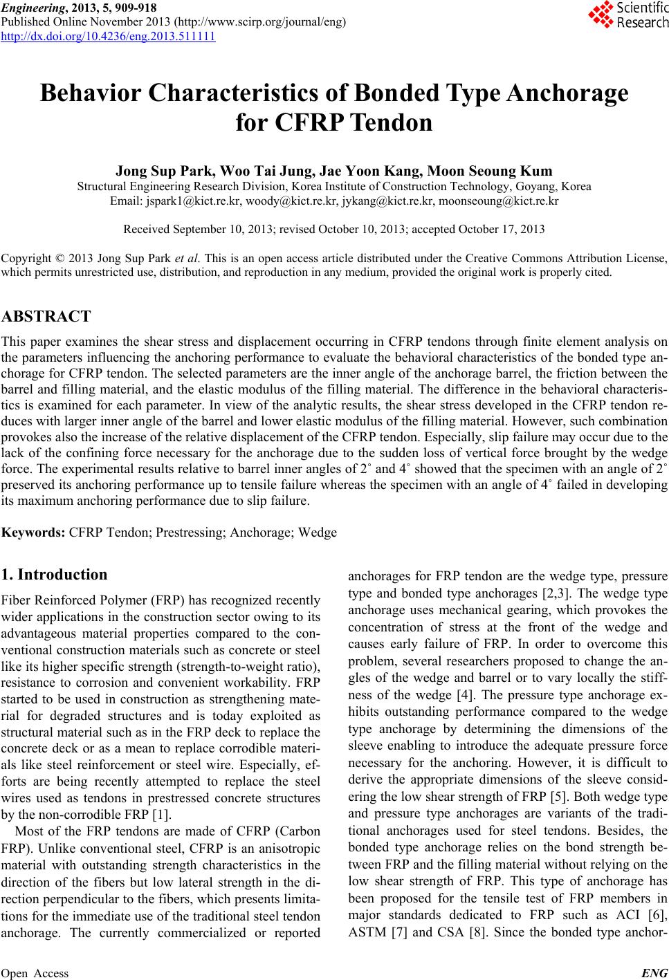 Engineering, 2013, 5, 909-918 Published Online November 2013 (http://www.scirp.org/journal/eng) http://dx.doi.org/10.4236/eng.2013.511111 Open Access ENG Behavior Characteristics of Bonded Type Anchorage for CFRP Tendon Jong Sup Park, Woo Tai Jung, Jae Yoon Kang, Moon Seoung Kum Structural Engineering Research Division, Korea Institute of Construction Technology, Goyang, Korea Email: jspark1@kict.re.kr, woody@kict.re.kr, jykang@kict.re.kr, moonseoung@kict.re.kr Received September 10, 2013; revised October 10, 2013; accepted October 17, 2013 Copyright © 2013 Jong Sup Park et al. This is an open access article distributed under the Creative Commons Attribution License, which permits unrestricted use, distribution, and reproduction in any medium, provided the original work is properly cited. ABSTRACT This paper examines the shear stress and displacement occurring in CFRP tendons through finite element analysis on the parameters influencing the anchoring performance to evaluate the behavioral characteristics of the bonded type an- chorage for CFRP tendon. The selected parameters are the inner angle of the anchorage barrel, the friction between the barrel and filling material, and the elastic modulus of the filling material. The difference in the behavioral characteris- tics is examined for each parameter. In view of the analytic results, the shear stress developed in the CFRP tendon re- duces with larger inner angle of the barrel and lower elastic modulus of the filling material. However, such combination provokes also the increase of the relative displacement of the CFRP tendon. Especially, slip failure may occur due to the lack of the confining force necessary for the anchorage due to the sudden loss of vertical force brought by the wedge force. The experimental results relative to barrel inner angles of 2˚ and 4˚ showed that the specimen with an angle of 2˚ preserved its anchoring performance up to tensile failure whereas the specimen with an angle of 4˚ failed in developing its maximum anchoring performance due to slip failure. Keywords: CFRP Tendon; Prestressing; Anchorage; Wedge 1. Introduction Fiber Reinforced Polymer (FRP) has recognized recently wider applications in the construction sector owing to its advantageous material properties compared to the con- ventional construction materials such as concrete or steel like its higher specific strength (strength-to-weight ratio), resistance to corrosion and convenient workability. FRP started to be used in construction as strengthening mate- rial for degraded structures and is today exploited as structural material such as in the FRP deck to replace the concrete deck or as a mean to replace corrodible materi- als like steel reinforcement or steel wire. Especially, ef- forts are being recently attempted to replace the steel wires used as tendons in prestressed concrete structures by the non-corrodible FRP [1]. Most of the FRP tendons are made of CFRP (Carbon FRP). Unlike conventional steel, CFRP is an anisotropic material with outstanding strength characteristics in the direction of the fibers but low lateral strength in the di- rection perpendicular to the fibers, which presents limita- tions for the immediate use of the traditional steel tendon anchorage. The currently commercialized or reported anchorages for FRP tendon are the wedge type, pressure type and bonded type anchorages [2,3]. The wedge type anchorage uses mechanical gearing, which provokes the concentration of stress at the front of the wedge and causes early failure of FRP. In order to overcome this problem, several researchers proposed to change the an- gles of the wedge and barrel or to vary locally the stiff- ness of the wedge [4]. The pressure type anchorage ex- hibits outstanding performance compared to the wedge type anchorage by determining the dimensions of the sleeve enabling to introduce the adequate pressure force necessary for the anchoring. However, it is difficult to derive the appropriate dimensions of the sleeve consid- ering the low shear strength of FRP [5]. Both wedge type and pressure type anchorages are variants of the tradi- tional anchorages used for steel tendons. Besides, the bonded type anchorage relies on the bond strength be- tween FRP and the filling material without relying on the low shear strength of FRP. This type of anchorage has been proposed for the tensile test of FRP members in major standards dedicated to FRP such as ACI [6], ASTM [7] and CSA [8]. Since the bonded type anchor- 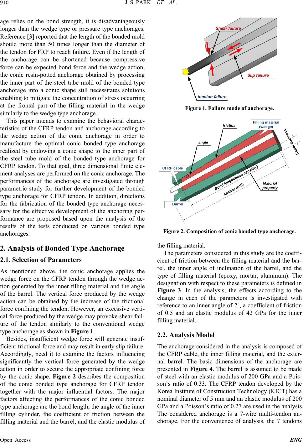 J. S. PARK ET AL. 910 age relies on the bond strength, it is disadvantageously longer than the wedge type or pressure type anchorages. Reference [3] reported that the length of the bonded mold should more than 50 times longer than the diameter of the tendon for FRP to reach failure. Even if the length of the anchorage can be shortened because compressive force can be expected bond force and the wedge action, the conic resin-potted anchorage obtained by processing the inner part of the steel tube mold of the bonded type anchorage into a conic shape still necessitates solutions enabling to mitigate the concentration of stress occurring at the frontal part of the filling material in the wedge similarly to the wedge type anchorage. This paper intends to examine the behavioral charac- teristics of the CFRP tendon and anchorage according to the wedge action of the conic anchorage in order to manufacture the optimal conic bonded type anchorage realized by endowing a conic shape to the inner part of the steel tube mold of the bonded type anchorage for CFRP tendon. To that goal, three dimensional finite ele- ment analyses are performed on the conic anchorage. The performances of the anchorage are investigated through parametric study for further development of the bonded type anchorage for CFRP tendon. In addition, directions for the fabrication of the bonded type anchorage neces- sary for the effective development of the anchoring per- formance are proposed based upon the analysis of the results of the tests conducted on various bonded type anchorages. 2. Analysis of Bonded Type Anchorage 2.1. Selection of Parameters As mentioned above, the conic anchorage applies the wedge force on the CFRP tendon through the wedge ac- tion generated by the inner filling material and the angle of the barrel. The vertical force produced by the wedge action can be obtained by the increase of the frictional force confining the tendon. However, an excessive verti- cal force produced by the wedge may provoke shear fail- ure of the tendon similarly to the conventional wedge type anchorage as shown in Figure 1. Besides, insufficient wedge force will generate insuf- ficient frictional force and may result in early slip failure. Accordingly, need it to examine the factors influencing significantly the vertical force generated by the wedge action in order to secure the appropriate confining force by the conic shape. Figure 2 describes the composition of the conic bonded type anchorage for CFRP tendon together with the major influential factors. The major factors affecting the performances of the conic bonded type anchorage are the bond length, the angle of the inner filling cylinder, the coefficient of friction between the filling material and the barrel, and the elastic modulus of Figure 1. Failure mode of anchorage. Barrel thickness Figure 2. Composition of conic bonded type anchorage. the filling material. The parameters considered in this study are the coeffi- cient of friction between the filling material and the bar- rel, the inner angle of inclination of the barrel, and the type of filling material (epoxy, mortar, aluminum). The designation with respect to these parameters is defined in Figure 3. In the analysis, the effects according to the change in each of the parameters is investigated with reference to an inner angle of 2˚, a coefficient of friction of 0.5 and an elastic modulus of 42 GPa for the inner filling material. 2.2. Analysis Model The anchorage considered in the analysis is composed of the CFRP cable, the inner filling material, and the exter- nal barrel. The basic dimensions of the anchorage are presented in Figure 4. The barrel is assumed to be made of steel with an elastic modulus of 200 GPa and a Pois- son’s ratio of 0.33. The CFRP tendon developed by the Korea Institute of Construction Technology (KICT) has a nominal diameter of 5 mm and an elastic modulus of 200 GPa and a Poisson’s ratio of 0.27 are used in the analysis. The considered anchorage is a 7-wire multi-tendon an- chorage. For the convenience of analysis, the 7 tendons Open Access ENG 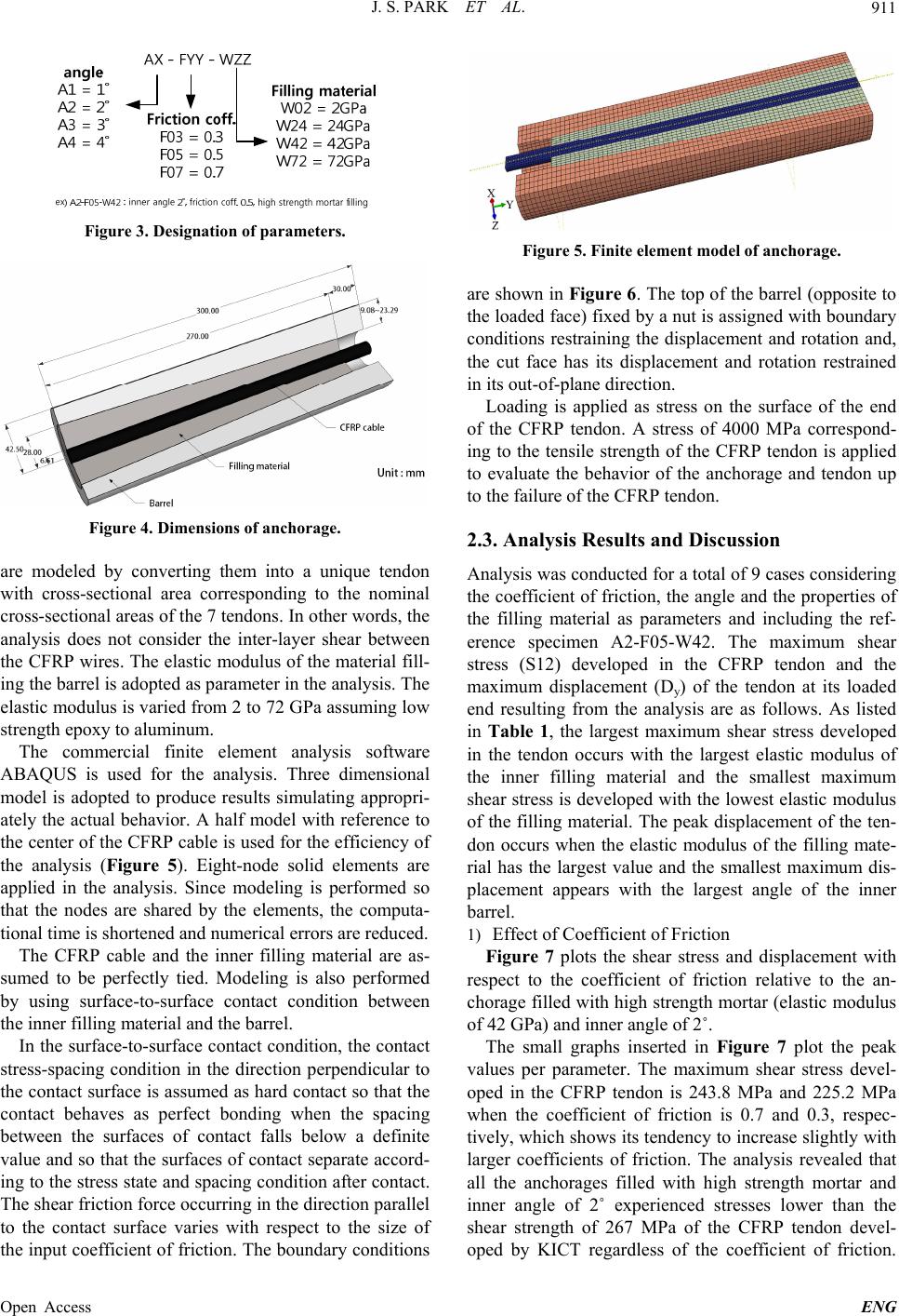 J. S. PARK ET AL. 911 Figure 3. Designation of parameters. Figure 4. Dimensions of anchorage. are modeled by converting them into a unique tendon with cross-sectional area corresponding to the nominal cross-sectional areas of the 7 tendons. In other words, the analysis does not consider the inter-layer shear between the CFRP wires. The elastic modulus of the material fill- ing the barrel is adopted as parameter in the analysis. The elastic modulus is varied from 2 to 72 GPa assuming low strength epoxy to aluminum. The commercial finite element analysis software ABAQUS is used for the analysis. Three dimensional model is adopted to produce results simulating appropri- ately the actual behavior. A half model with reference to the center of the CFRP cable is used for the efficiency of the analysis (Figure 5). Eight-node solid elements are applied in the analysis. Since modeling is performed so that the nodes are shared by the elements, the computa- tional time is shortened and numerical errors are reduced. The CFRP cable and the inner filling material are as- sumed to be perfectly tied. Modeling is also performed by using surface-to-surface contact condition between the inner filling material and the barrel. In the surface-to-surface contact condition, the contact stress-spacing condition in the direction perpendicular to the contact surface is assumed as hard contact so that the contact behaves as perfect bonding when the spacing between the surfaces of contact falls below a definite value and so that the surfaces of contact separate accord- ing to the stress state and spacing condition after contact. The shear friction force occurring in the direction parallel to the contact surface varies with respect to the size of the input coefficient of friction. The boundary conditions Figure 5. Finite element model of anchorage. are shown in Figure 6. The top of the barrel (opposite to the loaded face) fixed by a nut is assigned with boundary conditions restraining the displacement and rotation and, the cut face has its displacement and rotation restrained in its out-of-plane direction. Loading is applied as stress on the surface of the end of the CFRP tendon. A stress of 4000 MPa correspond- ing to the tensile strength of the CFRP tendon is applied to evaluate the behavior of the anchorage and tendon up to the failure of the CFRP tendon. 2.3. Analysis Results and Discussion Analysis was conducted for a total of 9 cases considering the coefficient of friction, the angle and the properties of the filling material as parameters and including the ref- erence specimen A2-F05-W42. The maximum shear stress (S12) developed in the CFRP tendon and the maximum displacement (Dy) of the tendon at its loaded end resulting from the analysis are as follows. As listed in Table 1, the largest maximum shear stress developed in the tendon occurs with the largest elastic modulus of the inner filling material and the smallest maximum shear stress is developed with the lowest elastic modulus of the filling material. The peak displacement of the ten- don occurs when the elastic modulus of the filling mate- rial has the largest value and the smallest maximum dis- placement appears with the largest angle of the inner barrel. 1) Effect of Coefficient of Friction Figure 7 plots the shear stress and displacement with respect to the coefficient of friction relative to the an- chorage filled with high strength mortar (elastic modulus of 42 GPa) and inner angle of 2˚. The small graphs inserted in Figure 7 plot the peak values per parameter. The maximum shear stress devel- oped in the CFRP tendon is 243.8 MPa and 225.2 MPa when the coefficient of friction is 0.7 and 0.3, respec- tively, which shows its tendency to increase slightly with larger coefficients of friction. The analysis revealed that all the anchorages filled with high strength mortar and inner angle of 2˚ experienced stresses lower than the shear strength of 267 MPa of the CFRP tendon devel- ped by KICT regardless of the coefficient of friction. o Open Access ENG 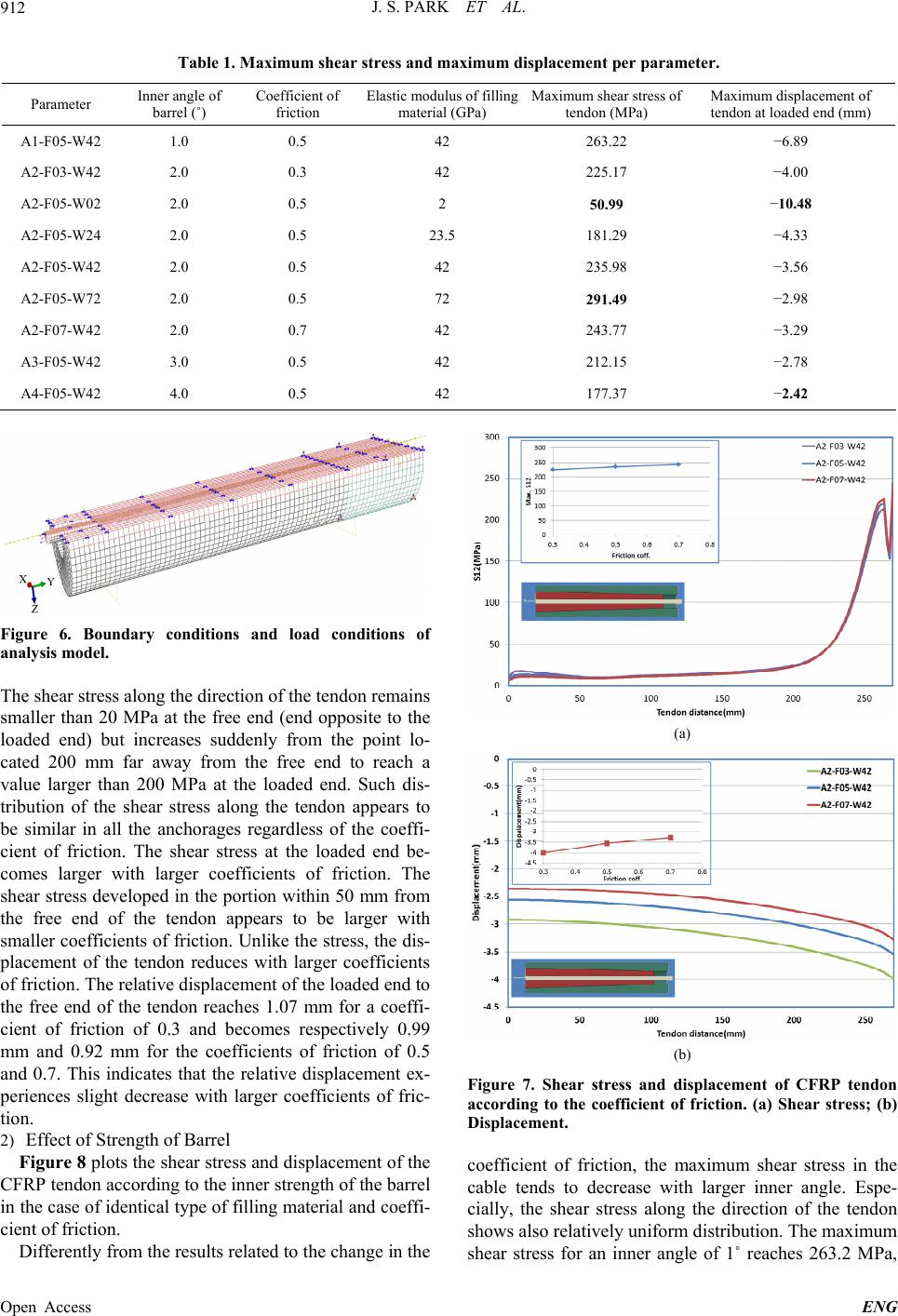 J. S. PARK ET AL. Open Access ENG 912 Table 1. Maximum shear stress and maximum displacement per parameter. Parameter Inner angle of barrel (˚) Coefficient of friction Elastic modulus of filling material (GPa) Maximum shear stress of tendon (MPa) Maximum displacement of tendon at loaded end (mm) A1-F05-W42 1.0 0.5 42 263.22 −6.89 A2-F03-W42 2.0 0.3 42 225.17 −4.00 A2-F05-W02 2.0 0.5 2 50.99 −10.48 A2-F05-W24 2.0 0.5 23.5 181.29 −4.33 A2-F05-W42 2.0 0.5 42 235.98 −3.56 A2-F05-W72 2.0 0.5 72 291.49 −2.98 A2-F07-W42 2.0 0.7 42 243.77 −3.29 A3-F05-W42 3.0 0.5 42 212.15 −2.78 A4-F05-W42 4.0 0.5 42 177.37 −2.42 Figure 6. Boundary conditions and load conditions of analysis model. The shear stress along the direction of the tendon remains smaller than 20 MPa at the free end (end opposite to the loaded end) but increases suddenly from the point lo- cated 200 mm far away from the free end to reach a value larger than 200 MPa at the loaded end. Such dis- tribution of the shear stress along the tendon appears to be similar in all the anchorages regardless of the coeffi- cient of friction. The shear stress at the loaded end be- comes larger with larger coefficients of friction. The shear stress developed in the portion within 50 mm from the free end of the tendon appears to be larger with smaller coefficients of friction. Unlike the stress, the dis- placement of the tendon reduces with larger coefficients of friction. The relative displacement of the loaded end to the free end of the tendon reaches 1.07 mm for a coeffi- cient of friction of 0.3 and becomes respectively 0.99 mm and 0.92 mm for the coefficients of friction of 0.5 and 0.7. This indicates that the relative displacement ex- periences slight decrease with larger coefficients of fric- tion. (a) (b) Figure 7. Shear stress and displacement of CFRP tendon according to the coefficient of friction. (a) Shear stress; (b) Displacement. 2) Effect of Strength of Barrel Figure 8 plots the shear stress and displacement of the CFRP tendon according to the inner strength of the barrel in the case of identical type of filling material and coeffi- cient of friction. Differently from the results related to the change in the coefficient of friction, the maximum shear stress in the cable tends to decrease with larger inner angle. Espe- cially, the shear stress along the direction of the tendon shows also relatively uniform distribution. The maximum shear stress for an inner angle of 1˚ reaches 263.2 MPa,  J. S. PARK ET AL. 913 (a) (b) Figure 8. Shear stress and displacement of CFRP tendon according to the inner angle. (a) Shear stress; (b) Displace- ment. which corresponds to 99% of the shear strength of the CFRP tendon. In the anchorage with an inner angle of 4˚, the maximum shear stress reaches 177.4 MPa corre- sponding to a reduction of approximately 33% compared to the shear stress for the inner angle of 1˚. As shown in Figure 8, the shear stress in the portion within about 80 mm from the free end of the CFRP ten- don decreases with smaller inner angle and the shear stress in the portion from 80 mm and 230 mm from the free end increases with smaller inner angle. This means that the shear stress concentrates at the loaded end of the tendon as much as the inner angle is small and tends to distribute relatively along the length of the tendon with larger inner angle. Such stress distribution can be attrib- uted to the reduction of the force produced by the wedge action consecutive to the increase of the inner angle and to the fact that the anchorage by bonding governs the performance. The relative displacement between the free end and loaded end of the tendon shows practically no change according to the variation of the inner angle. The relative displacement for an inner angle of 1˚ reaches 1.015 mm and reaches 1.020 mm for an inner angle of 4˚ represent- ing merely a difference of 0.5% between these two an- gles. However, the displacement provoked by the wedge sliding appears to increase with smaller inner angle. Es- pecially, the sliding displacement of the tendon for the inner angle of 1˚ is larger by about 4 times compared to that corresponding to the inner angle of 4˚. 3) Effect of the Properties of the Filling Material Figure 9 plots the shear stress and displacement of the cable according to the properties of the filling material. As shown in Figure 9, the physical properties of the filling material inside the conic anchorage have the larg- est effect on the maximum shear stress of the CFRP ten- don compared to the coefficient of friction and inner an- gle. The maximum shear stress occurring in the tendon according to the elastic modulus of the inner filling ma- terial is seen to vary from 51.0 MPa and 291.5 MPa. When using epoxy, the filling material with very low elastic modulus, the maximum shear stress in the CFRP tendon reaches 51.0 MPa corresponding to 19% of the shear strength of the CFRP tendon and shows even dis- tribution ranging from 35 MPa to 51 MPa along the (a) (b) Figure 9. Shear stress and displacement of CFRP tendon according to the properties of the filling material. (a) Shear stress; (b) Displacement. Open Access ENG  J. S. PARK ET AL. Open Access ENG 914 3. Test and Verification of the Anchorage tendon. The maximum shear stress in the CFRP tendon experiences also sudden increase with larger elastic modulus of the filling material. In the anchorage assumed to be filled with aluminum, the maximum shear stress reaches 291.5 MPa resulting to the shear failure of the tendon prior to the tensile failure of the CFRP tendon. Accordingly, the physical properties of the filling mate- rial appear to have effect on the mitigation of the con- centration of the shear stress. Especially, the use of a filling material with low elastic modulus is seen to be effective in reducing the significant shear stress occur- ring at the loaded end of the tendon. Based upon this observation, Figure 10 illustrates the solutions proposed for the anchorage for CFRP tendon by filling the an- chorage by a low elastic modulus material in the portion featured by the concentration of stress [9]. 3.1. Material Test of CFRP Tendon The CFRP tendon considered in this study is made of 5 mm-diameter steel wires that have not received separate surface treatment. Therefore, tensile test was conducted in compliance with the testing method of [1] proposed by modifying the CSA testing method. In order to improve the bond performance of the non-surface treated tendons, the cross-section of the tendon was quadrisected longitu- dinally to increase the bond area and alumina oxide coating was applied on the surface to secure sufficient bond performance between the filling material and the tendon as shown in Figure 11. Figure 12 illustrates the strengthening of the extremity by using small quantities of fiber to prevent longitudinal splitting. In Figure 9(b) plotting the displacement of the CFRP tendon with respect to the physical properties of the fill- ing material, it can be observed that comparatively larger difference in the relative displacement between the free end and loaded end of the tendon is obtained than in the analysis results corresponding to the variation of the co- efficient of friction or inner angle. The sliding of the in- ner filling material becomes significant with lower elastic modulus of the filling material. The relative displacement between the free end and loaded end of the CFRP tendon also shows a tendency to increase in such case. For the parameter A2-F05-W02 exhibiting the lowest elastic modulus of the filling material, the sliding of the free end of the CFRP tendon reaches 7.86 mm and the relative displacement between the free end and loaded end of the tendon is 2.62 mm. For the parameter A2-F05-W72 ex- hibiting the highest elastic modulus of the filling material, the sliding of the free end of the CFRP tendon reaches 2.98 mm and the relative displacement between the ends of the tendon is 1.35 mm. The so-treated CFRP tendon was then aligned in the steel tube as shown in Figure 13 and the specimen was filled with non-shrinkage mortar as applied in the refer- ence specimen in the analysis. The tensile test was per- formed after completion of more than 7 days of curing for the mortar to develop sufficient strength. Figure 14 presents the compressive strength per age of the mortar used as filling material. A water-to-mortar ratio of 16% was adopted considering the workability of mortar during filling. A UTM (Universal Testing Machine) with capacity of 980 kN was used for the tensile test of the CFRP tendon. Loading was applied through displacement control at speed of 0.0835 mm/sec. Tensile test was conducted on a total of 10 tensile specimens. All the specimens failed typically through tensile failure of FRP (Figure 15). All the specimens exhibited strength higher than the nomi- nal strength of 4000 MPa specified by the manufacturer. The tensile test results of each specimen are listed in Ta- ble 2. Figure 10. Solutions for the mitigation of shear stress.  J. S. PARK ET AL. 915 Figure 11. Quadrisected and oxide coated extremity of CFRP tendon. Figure 12. Fiber reinforcement of tendon end. Figure 13. Specification of steel molds. 3.2. Test ic anchorag sis model of this study, preliminary test was conducted on the anchorage with 7 multi-ten- of 7-CFRP Wire Anchorage 1) Preliminary Test Prior to the test on the bonded type cone addressed in the analy Figure 14. Compressive strength of mortar. Figure 15. View of tensile test and failure pattern. dons to verify the anchoring performance of the bonded type anchorage (Table 3). In the preliminary test, tensile test is carried out on a specimen with the extremity of eachtest f the single tendon and a specimen in which the tendons ing to 58% of the esponding to 94% of dge e specimens were manufactured to pr ered in the analysis. Test was also additionally conducted individual tendon processed like in the tensile o are disposed with large spacing and without particular treatment of the extremities. Here also, both specimens have their surface coated with alumina oxide so as to increase the surface bond strength. The test was conducted using the same method as the tensile test of the CFRP tendon. The final test results are arranged in Table 4. The simply bonded preliminary test specimen II failed through slip in the individual tendons at loading of 319.81 kN correspond nominal strength of the CFRP tendon. Figure 16 plots the load-displacement curve measured on the preliminary test specimen I of which the bond surface was enlarged. It can be seen that slip occurred locally around 310 kN and that the final slip failure (Figure 17) occurred at 516.05 kN corr the nominal tensile strength of the CFRP tendon. 2) Preliminary Test The simple bonded type anchorage failed to develop 100% of its anchoring performance by slip. The test on the conic bonded type anchorage demonstrated the effec- tive improvement of the bond performance by the we action. The anchorag esent inner angles of 2˚ and 4˚ in the barrel as consid- Open Access ENG  J. S. PARK ET AL. 916 Table 2. Maximum shear stress and maximum displacement per parameter. Specimen Maximum load (kN) Tensile strength (MPa)Maximum displacement (mm)Strain (10−6) Elastic modulus (GPa) 1 86.77 4419 20.20 - 231.59 2 89.12 4538 20.10 17,748 242.32 3 90.25 4596 21.79 18,3 70237.18 4 87.82 4472 21.26 17,345 238.28 5 88.23 4493 20.35 - 239.15 6 81.59 4155 16.76 15,258 236.14 7 89.23 4544 17.05 17,3 13239.59 8 84.96 4327 17.62 15,806 230.35 9 86.85 4423 16.57 16,957 240.57 10 82.10 4181 15.61 16,608 235.23 Mean 86.69 4414 18.73 237.04 le 3. Prelimint variables for 7-. Dimensions of steel tube (mm) Tabary teswire Preliminary te Treatment of tendon end st Outer diameter Thickness I 76.3 7 Enlargement of bond area II 76.3 7 Simple bond Figure 16. Load-displacement curve of preliminary test specimen I. omparison with the simple bonded type an- horage. The major dimensions of the anchorages are on an anchorage specimen with inner barrel angle of 0˚ for further c c presented in Figure 18. The anchorages were fabricated to be supported by means of a nut identically to the analysis model. The treatment of the extremity of the CFRP tendons and the test were carried out identically to the methods adopted for preliminary test specimen I. The final failure patterns of the 7-wire anchorages are Figure 17. Slip failure pattern at the extremity of the preliminary test specimens. (a) Specimen I; (b) Specimen II. illustrated in Figure 19. Figure 20 plots the correspond- ing load-displacement curves. The simple bonded type anchorage with inner angle f 87.19 kN through the breakage of the CFRP tendon. avior until its final fail- ur o 0˚ (M7-0) experienced local slip around 350 kN similarly to the preliminary test but final failure occurred at load of 5 Unlike specimen M7-0, the specimen with inner angle of 2˚ (M7-2) preserved a linear beh e at 599.71 kN through rupture of the CFRP tendon. The absence of slip in M7-2 can be explained by the con- finement of the tendon by the lateral force produced by the wedge action. The specimen with inner angle of 4˚ (M7-4) experienced slip at 342.73 kN and final failure at 481.29 kN. As seen in the analysis results, the lateral force generated by wedge action in specimen M7-4 ap- pears to be insufficient in anchoring the tendon. Espe- cially, it seems also that the inner space of the barrel narrowed by the inner angle was insufficient to secure the density of the filling mortar. As shown in Figure 19(c), the core wire located at the center of specimen M7-4 was practically not anchored and resulted in the failure of the remaining 6 wires around the peak tensile load of 471 kN. Open Access ENG  J. S. PARK ET AL. 917 Figure 18. Dimensions and shape s of 7-wire anchorage specimens. Table 4. Results of preliminary test of 7-wire. Specimen Maximum load (kN) Tensile strength of CFRP (MPa)Maximum displacement (mm)Strain (10−6) Elastic modulus (GPa) Preliminary specimen I 516.05 3755 33.33 15,925 232 Prelimen II inary specim319.81 2326 12.92 10,773 221 (a) (b) (c) Figure 19. Failure patterns of 7-wire anchorage. (a) M7-0; (b) M7-2; (c) M7-4. Figure 20. Load-displacement curve of 7-wire anchorage. 4. Conclusion This study intended to investigate the behavioral charac- teristics of the bonded type anchorage for CFRP tendon. To that goal, finite element analysis was conducted on the parameters affecting the anchoring performance and the shear stress and displacement occurring in the CFRP tendon were analyzed. The analysis results revealed that the shear stress developed in the CFRP tendon decreased with larger inner angle of the barrel and lower elastic modulus of the filling material. However, this combina- tion resulted also in the sudden loss of the vertical force generated by the wedge force leading to the lack of con- fining force necessary for the anchoring and subse- q of 1˚, it appeared that the shear stress uently to the occurrence of slip failure. In the case of an inner barrel angle close to the shear strength of CFRP tendon was devel- oped. In the case of an elastic modulus of 72 GPa for the filling material, shear stress larger than the shear strength developed resulting in the occurrence of shear failure in the anchorage prior to the tensile failure of the tendon. Open Access ENG  J. S. PARK ET AL. 918 Based upon these results, the optimal bonded type an- chorage appeared to be the anchorage with inner barrel angle of 2˚ and is filled with mortar. Therefore, tests were carried out on specimens with inner barrel angles of 0˚, 2˚ and 4˚ to verify the analysis results. The experi- mental results also showed that the simple bonded type anchorage specimens with inner barrel angles of 0˚ and 4˚ failed in developing their maximum performance due to slip failure whereas the specimen with inner barrel angle of 2˚ was able to exhibit its anchoring performance up to the tensile failure of the tendon, which confirmed the analysis results. 5. Acknowledgements This research was supported by grant from Strategic Re- search Project (Development of Bridge Strengthening Method using Prestressed FRP Composites) funded by Korea Institute of Construction Technology. REFERENCES [1] W. T. Jung and J. S. Park, “An Experimental Study on Tensile Characteristic for CFRP Cable without Surface Treatments,” Procedia Engineering, Vol. 14, 2011, pp. 1518-1523. http://dx.doi.org/10.1016/j.proeng.2011.07.191 [2] A. Nanni, C. E. Bakis, P. E. O’Niel and T. O. Dixon, “Performance of FRP Tendon-Anchor Systems for Pre- ,” PCI Journal, Vol. 41, . , pp. 88-100. ol. 3, No. 1-3, 1996, pp. 379-384. Nostressed Concrete Structures. 1, 1996, pp. 34-43. [3] J. A. Pincheira and J. P. Woyak, “Anchorage of Carbon Fiber Reinforced Polymer (CFRP) Tendons Using Cold- Swaged Sleeves,” PCI Journal, Vol. 46, No. 6, 2001, pp 100-111. [4] A. Al-Mayah, K. A. Soudki and A. Plumtree, “Experi- mental and Analytical Investigation of a Stainless Steel Anchorage for CFRP Prestressing Tendons,” PCI Journal, Vol. 46, No. 2, 2001 [5] E. A. Shaheen, “Carbon Fibre Reinforced Reactive Pow- der Concrete (CFRRPC) Anchorage System,” Ph.D. The- sis, University of Calgary, Calgary, 2004. [6] ACI Committee 440, “Guide Test Methods for Fiber-Re- inforced Polymers (FRPs) for Reinforcing or Strengthen- ing Concrete Structures,” ACI 440.3R-04, 2004. [7] ASTM D 3916-08, “Standard Test Method for Tensile Properties of Pultruded Glass-Fiber-Reinforced Plastic Rod,” 2008. [8] Canadian Standard Association (CSA), “CSA Standard S806-02, Design and Construction of Building Compo- nents with Fiber-Reinforced Polymers,” 2002. [9] U. Meier and M. Farshad, “Connecting High-Perfor- mance Carbon-Fibre-Reinforced Polymer Cables of Sus- pension and Cable-Stayed Bridges through the Use of Gradient Materials,” Journal of Computer-Aided Materi- als Design, V http://dx.doi.org/10.1007/BF01185676 Open Access ENG |