Engineering, 2013, 5, 902-908
Published Online November 2013 (http://www.scirp.org/journal/eng)
http://dx.doi.org/10.4236/eng.2013.511110
Open Access ENG
Parametric Analysis on the Optimal Dimensions of Steel
Sleeve in Swaging Type Anchorage for CFRP Tendon
Jae Yoon Kang, Jong Sup Park, Woo Tai Jung, Moon Seoung Kum
Structural Engineering Research Division, Korea Institute of Construction Technology, Goyang, Korea
Email: jykang@kict.re.kr, jspark1@kict.re.kr, woody@kict.re.kr, moonseoung@kict.re.kr
Received September 11, 2013; revised October 11, 2013; accepted October 18, 2013
Copyright © 2013 Jae Yoon Kang et al. This is an open access article distributed under the Creative Commons Attribution License,
which permits unrestricted use, distribution, and reproduction in any medium, provided the original work is properly cited.
ABSTRACT
This paper presents the parametric analysis conducted to derive the optimal dimensions of the steel sleeve necessary to
secure the bond performance of the swaging type anchorage for CFRP tendon with diameter of 5 mm. To that goal, fi-
nite element analysis is performed on the parameters determining the dimensions of the sleeve like the thickness and
inner diameters of the sleeve. The results show that a constant swaging pressure of about 450 MPa on the mean is dis-
tributed in the sleeve when the thickness ratio of the stress relief zone to the effective swaging zone of the sleeve is lar-
ger than 1.1 and that the swaging pressure tends to reduce linearly as much as this thickness ratio becomes smaller than
1.1. The pressure varies within a range of about 30% according to the change in the inner diameter of the sleeve
whereas varies within a range less than 10% according to the change in the inner diameter when the thickness ratio is
larger than 1.1. Finally, the optimal dimensions of the steel tube sleeve enabling to secure an anchor force larger than
the rupture streng th of the CFRP tendon w ith diameter of 5 mm are determined based upon the results of the pa rametric
analysis.
Keywords: CFRP Tendon; Prestressing; Swaging Type Anchorage; Swaging Sleeve
1. Introduction
Recently, research has been actively conducted on the
repair and strengthening of structures using carbon fi-
ber-reinforced polymer (CFRP) material. Research is
also performed on the improvement of the strengthening
efficiency of the conventional method simply bonding
sheet or bar-shaped reinforcement on the surface of the
member by embedding the reinforcement near the sur-
face (NSM, Near Surface Mounted) or by introducing a
jacking force simultaneously to the NSM [1,2].
The methods adopted to anchor CFRP tendon can be
classified into the wedge type, the bonded type and
swaging type anchors. The wedge type anchorage gener-
ally adopted for anchoring PS steel wires or PS steel
strands uses mechanical gearing through a wedge system
which compresses the circumference of the tendon. The
bonded type anchorage is a system which fills a steel
pipe with expansive material or resin and secures its an-
chor performance by the bond force between the tendon
and the filling material. The bonded type anchorage pro-
vokes lesser damage to the tendon than the wedge type
and swaging type anchorages but presents the problem of
becoming longer with larger sleeve since the anchor per-
formance depends on the bond performance brought by
the external shape and sheath of the tendon.
As shown in Figure 1, the swaging type or compres-
sion type anchor applies a pressure on the outer circum-
ference of the steel pipe (sleeve) to increase the friction
on the circumference of the tendon. Unlike the bonded
type, this type of anchor do es not require a curing period
for the filling material and enables to shorten the length
of the sleeve by more than 33%. Jung et al. [3] evaluated
the anchor performance of the swaging type anchor
through an experimental study considering various pa-
rameters including the dimensions of the sleeve, and the
eventual presence of insert. Their experimental results
revealed that the anchor performance of the swaging type
anchor varied according to the change in the swaging
pressure itself depending on the inner and outer diame-
ters of the sleeve. The authors reported also that the need
was to mitigate the concentration of stress at the end of
the sleeve by disposing a stress relief zone in order to
prevent the ruptur e of the tendon at the end of the sleeve.
These authors also reported that anchor performance
reaching 94% of the rupture load of the tendon could be
J. Y. KANG ET AL. 903
Figure 1. Compression scheme for compression type anchor
[3].
obtained in the case of an inner diameter of the sleeve of
12 mm for a 9.5 mm tendon, that the optimal length of
the taper was 40 mm and that a constant swaging pres-
sure should be secured over a length longer than 80 mm
to obtain sufficient swaging pressure for the anchor.
In addition, Jung et al. [3] examined the variation of
stress according to the change in the inner diameter of
the sleeve through finite element analysis as shown in
Figure 2. This analysis enabled to state the existence of
an adequate stress and of corresponding optimal dimen-
sions of the sleeve to secure the tendon anchor perform-
ance.
This study focuses on the variation of swaging pres-
sure according to the thickness of the sleeve for the
swaging type anchor for CFRP bar with diameter of 5
mm. The distribution characteristics of the swaging
pressure are examined with respect to the thickness ratio
of the stress relief zone to the effective swaging zone
through finite element analysis. Finally, the optimal di-
mensions of the sleeve en abling to obtain the appropriate
pressure are derived to secure the bond force of the
CFRP tendon.
2. Swaging Stress According to the Change
in the Sleeve Thickness t0
2.1. Description of Analysis Model
The parametric analysis is performed using the finite
element analysis software ABAQUS v.6.5. The steel pipe
is modeled by means of planar axial symmetric model
considering the symmetry of the pipe, and the dice is
modeled as a rigid body. Loading is applied as shown in
Figure 3 so as to push the rear face of the sleeve by dis-
placement control up to 160 mm considering the fabrica-
tion method of the real swaging sleeve. This loading
method enables to provoke swaging by gearing induced
by friction with the CFRP tendon by generating the
swaging deformation when penetrating the steel dice. At
that time, the steel sleeve and the CFRP tendon are en-
dowed with contact boundary conditions. In the contact
boundary conditions, the coefficient of friction between
the sleeve and the tendon is set conservatively to 0.15
referring to the value of 0.23 applied for the initial coef-
ficient of friction be tween CFRP and the aluminum plate
in a previous study [4] and considering the absence of
studies dedicated to the coefficient of friction between
Figure 2. Swaging pressures developed in 9.5 mm CFRP
tendon [3].
Figure 3. Loading method and analysis model.
the CFRP bar and the steel sleeve. Hard contact condi-
tion is adopted for the direction perpendicular to the
contact surface. The boundary conditions are set so as to
enable separation of the contact surface for the behavior
in the perpendicular direction after contact. Note that the
friction force between the dice and sleeve is neglected
and attributed with frictionless conditions.
The material properties of the CFRP tendon and steel
sleeve are listed in Table 1.
2.2. Range of Parameters
Table 2 arranges the range of the parameters for the
analysis and shows the analysis conditions for the
evaluation of the variation in the swaging pressure with
respect to the change in the thickness of the steel pipe
sleeve. For the CFRP tendon with diameter of 5 mm, the
inner diameter of the sleeve, the length of the stress relief
zone and the effective swaging zone in Figure 4 are re-
spectively set to 6.5 mm, 40 mm and 80 mm. The varia-
tion of the contact pressure developed inside the sleeve is
evaluated by changing the thickness t0 of the stress relief
zone and the thickness t of the effective swaging zone.
Especially, focus is done on the variation of the swaging
pressure according to the ratio of the thickness of the
steel sleeve to the thickness of the taper ( t/t0). The analy-
sis intends to determine the thickness range enabling to
minimize the concentration of stress occurring in the
CFRP tendon and to obtain stable anchor effect.
In the analysis, the inner diameter of the dice is set
with the value obtained by subtracting (d1c) to the di-
ameter d2 so that the outer diameter of the sleeve pene-
trating the dice becomes fixed to t0 and becomes bonded
to the tendon.
Open Access ENG
J. Y. KANG ET AL.
Open Access ENG
904
Figure 4. Definition of the dimensions of steel sleeve.
Table 1. Material properties of CFRP tendon and steel sleeve.
Member Elastic modulus (MPa) Yield strength (MPa) Tensile strength (MPa)Diameter (mm) Cross sectional area (mm2)
CFRP tendon (5.0) 165,000 – 3500 5.0 19.63
Steel pipe sleeve 200,000 400 569 -
Table 2. Range of parameters in analysis (variation of sleeve thickness).
dc d1 t0 t t/t0 d2 d3 Lr Le Designation of model
4.12 1.03 14.7 S1-65-t4-e0
4.20 1.05 14.9 S1-65-t4-e1
4.28 1.07 15.1 S1-65-t4-e2
4.40 1.10 15.3 S1-65-t4-e3
4.0
4.52 1.13
14.5
15.5 S1-65-t4-e4
5.15 1.03 16.8 S1-65-t5-e0
5.25 1.05 17.0 S1-65-t5-e1
5.35 1.07 17.2 S1-65-t5-e2
5.50 1.10 17.5 S1-65-t5-e3
5.0
5.65 1.13
16.5
17.8 S1-65-t5-e4
6.18 1.03 18.9 S1-65-t6-e0
6.30 1.05 19.1 S1-65-t6-e1
6.42 1.07 19.3 S1-65-t6-e2
6.60 1.10 19.7 S1-65-t6-e3
6.0
6.78 1.13
18.5
20.1 S1-65-t6-e4
7.21 1.03 20.9 S1-65-t7-e0
7.35 1.05 21.2 S1-65-t7-e1
7.49 1.07 21.5 S1-65-t7-e2
7.70 1.10 21.9 S1-65-t7-e3
5.0 6.5
7.0
7.91 1.13
20.5
22.3
48.0 80.0
S1-65-t7-e4
J. Y. KANG ET AL. 905
2.3. Analysis Results
Figure 5 shows the change of the pr essure distribution in
the cross section during the analysis process. It appears
that the pressure distribution in the sleeve exhibits con-
stant size after completion of swaging. This study also
performs comparative analysis of the mean pressure oc-
curring in the effective swaging zone of the steel sleeve
for each analysis model. Figure 6 compares the distribu-
tion of the pressure in the sleeve according to the in-
crease of the thickness t of the effective swaging zone
when the thickness of the steel pipe sleeve takes respec-
tive values of 4, 5, 6 and 7 mm.
In Figure 6, the lowest pressure distribution is ob-
served the thickness ratio (t/t0) has a very small value of
1.03. The variation in the pressure tends to increase ac-
cording to the thickness ratio (t/t0) when the thickness t0
becomes larger.
Figure 7 compares the mean pressure developed in the
effective swaging zone according to the variation of the
thickness (t0) of the sleeve and thickness ratio (t/t0). The
variation of the pressure tends to widen according to the
change in the thickness ratio for larger thickness of the
sleeve.
Figure 8 compares the maximum pressure according
to the change in the thickness ratio for each considered
sleeve thickness (t0). It appears that the variation of the
pressure is minimized for an arbitrary sleeve thickness
when the thickness ratio is 1.10. In such case, the mean
pressure developed in the sleeve runs around 450 MPa. It
can thus be expected that a constant swaging pressure
can be achieved if the thickness of the effective swaging
zone t is decided to set the thickness ratio to 1.10 for an
arbitrary sleeve thickness.
3. Swaging Pressure Ac cording to the
Change in the Sleeve Inner Diameter (d1)
and Thickness Ratio (t/t0)
3.1. Range of Parameters
In order to investigate the swaging performance accord-
ing to the variations of the inner diameter and thickness
of the sleeve, the change in pressure is examined accord-
ing to the variations of the inner diameter of the sleeve
(d1) and the thickness of the effective swaging zone (t)
while fixing the values of the inner diameter of the dice
to 16 mm and the thickness (t0) of the steel pipe to 5.5
mm. The value of 5.5 mm for t0 has been chosen to in-
crease gradually the pressure in the stress relief zone
without occurrence of swaging-induced pressure at the
head when the dice with diameter of 16 mm is com-
pressed during the penetration and to secure a constant
pressure in the effective swaging zone. The thickness t of
the effective swaging zone is decided to achieve a thick-
ness ratio (t/t0) ranging between 1.04 and 1.16. Three
different values of 5.5, 6.1 and 6.5 mm are adopted for
the inner diameter of the sleeve. Table 3 arranges the
values of the parameters for each analysis model.
Figure 5. Pressure distribution in cross section during the analysis process.
Open Access ENG
J. Y. KANG ET AL.
906
020406080100 120 140
0
100
200
300
400
500
Contact Pressure (M P a )
Location in Sl eeve (mm)
t/t0=1.03 t/t0=1.05
t/t0=1.07 t/t0=1.10
t/t0=1.13
020406080100 120 140
0
100
200
300
400
500
Contact Pressure (MPa)
Location in Sleeve (mm)
t/t0=1.03 t/t0=1.05
t/t0=1.07 t/t0=1.10
t/t0=1.13
(a) (b)
020 40 60 80100120140
0
100
200
300
400
500
Contact Pressure (MP a)
Locatio n i n Sleeve (mm)
t/t0=1.03
t/t0=1.05
t/t0=1.07
t/t0=1.10
t/t0=1.13
020 40 60 80100120140
0
100
200
300
400
500
Contact Pressure (MPa)
Location in Sleeve (mm)
t/t0=1.03
t/t0=1.05
t/t0=1.07
t/t0=1.10
t/t0=1.13
(c) (d)
Figure 6. Pressure distribution in sleeve according to the thickness t0 of steel pipe. (a) t0 = 4 mm; (b) t0 = 5 mm; (c) t0 = 6 mm;
(d) t0 = 7 mm.
4.0 4.5 5.0 5.5 6.0 6.5 7.0
0
100
200
300
400
500
Contact Pressure (MPa)
Thickness of Sleeve, t0 (mm)
t/t0=1.03
t/t0=1.05
t/t0=1.07
t/t0=1.10
t/t0=1.13
Figure 7. Comparison of mean pressure in sleeve according
to t/t0.
1.02 1.04 1.06 1.08 1.10 1.12 1.14
0
100
200
300
400
500
Contact Pressure (MPa)
t/t0
t0=4mm
t0=5mm
t0=6mm
t0=7mm
Figure 8. Comparison of mean pressure in sleeve according
o the change of the steel pipe thickness t0.
t
Open Access ENG
J. Y. KANG ET AL. 907
Table 3. Range of parameters in analysis (variations of inner diameter and thickness of sleeve).
t0 t d1 d2 = d1 + 2t0 (1) d3 = d1 + 2t (2) Diameter of dice (3)(1)/(3) (2)/(3) t/t0 Designation of model
5.7 16.9 1.059 1.04 S5-1-1
5.8 17.2 1.073 1.06 S5-1-2
5.9 17.4 1.086 1.08 S5-1-3
6.1 17.6 1.100 1.10 S5-1-4
6.2 17.8 1.114 1.12 S5-1-5
6.3 18.0 1.128 1.14 S5-1-6
6.4
5.5 16.5
18.3
1.031
1.141 1.16 S5-1-7
5.7 17.4 1.090 1.04 S5-2-1
5.8 17.7 1.104 1.06 S5-2-2
5.9 17.9 1.118 1.08 S5-2-3
6.1 18.1 1.131 1.10 S5-2-4
6.2 18.3 1.145 1.12 S5-2-5
6.3 18.5 1.159 1.14 S5-2-6
6.4
6.0 17.0
18.8
1.063
1.173 1.16 S5-2-7
5.7 17.9 1.121 1.04 S5-3-1
5.8 18.2 1.135 1.06 S5-3-2
5.9 18.4 1.149 1.08 S5-3-3
6.1 18.6 1.163 1.10 S5-3-4
6.2 18.8 1.176 1.12 S5-3-5
6.3 19.0 1.190 1.14 S5-3-6
5.50
6.4
6.5 17 .5
19.3
16.0
1.094
1.204 1.16 S5-3-7
3.2. Analysis Results
Figure 9 plots the distribution of the pressure developed
in the sleeve according to the thickness ratio (t/t0). It can
be verified that the pressure increases progressively in
the stress relief zone to exhibit a constant value in the
effective swaging zone.
Figure 10 compares the mean pressure developed in
the effective swaging zone. It can be seen that the mean
pressure tends to redu ce linearly with the decrease of the
thickness ratio when the thickness ratio is smaller than
1.1 and, the pressure keeps a constant value higher than
approximately 440 MPa even if the thickness ratio in-
creases when this ratio is larger than 1.1. The pressure
according to varying inner diameter shows poor variation
below about 10% when the thickness ratio is larger than
1.1 but exhibits increased variation as much as the thick-
ness ratio reduces below 1.1. This difference in the pres-
sure reaches a maximum of 30% when the thickness ratio
is 1.04.
-20020406080100 120 140
0
100
200
300
400
500
600
Contact Pressure (MPa)
Location in Sleeve (mm)
t/t
0
=1.04
t/t
0
=1.06
t/t
0
=1.08
t/t
0
=1.10
t/t
0
=1.12
t/t
0
=1.14
t/t
0
=1.16
Figure 9. Distribution of pressure in sleeve according to the
variation of t/t0.
4. Conclusions
This paper presented the results of a parametric analysis
Open Access ENG
J. Y. KANG ET AL.
908
1.04 1.06 1.08 1.10 1.12 1.14 1.16 1.18
100
150
200
250
300
350
400
450
500
Contact P ressure (MPa)
t/t0
d1=5.5mm
d1=6.0mm
d1=6.5mm
16mm
t0=5.5mmt
d1
5mm
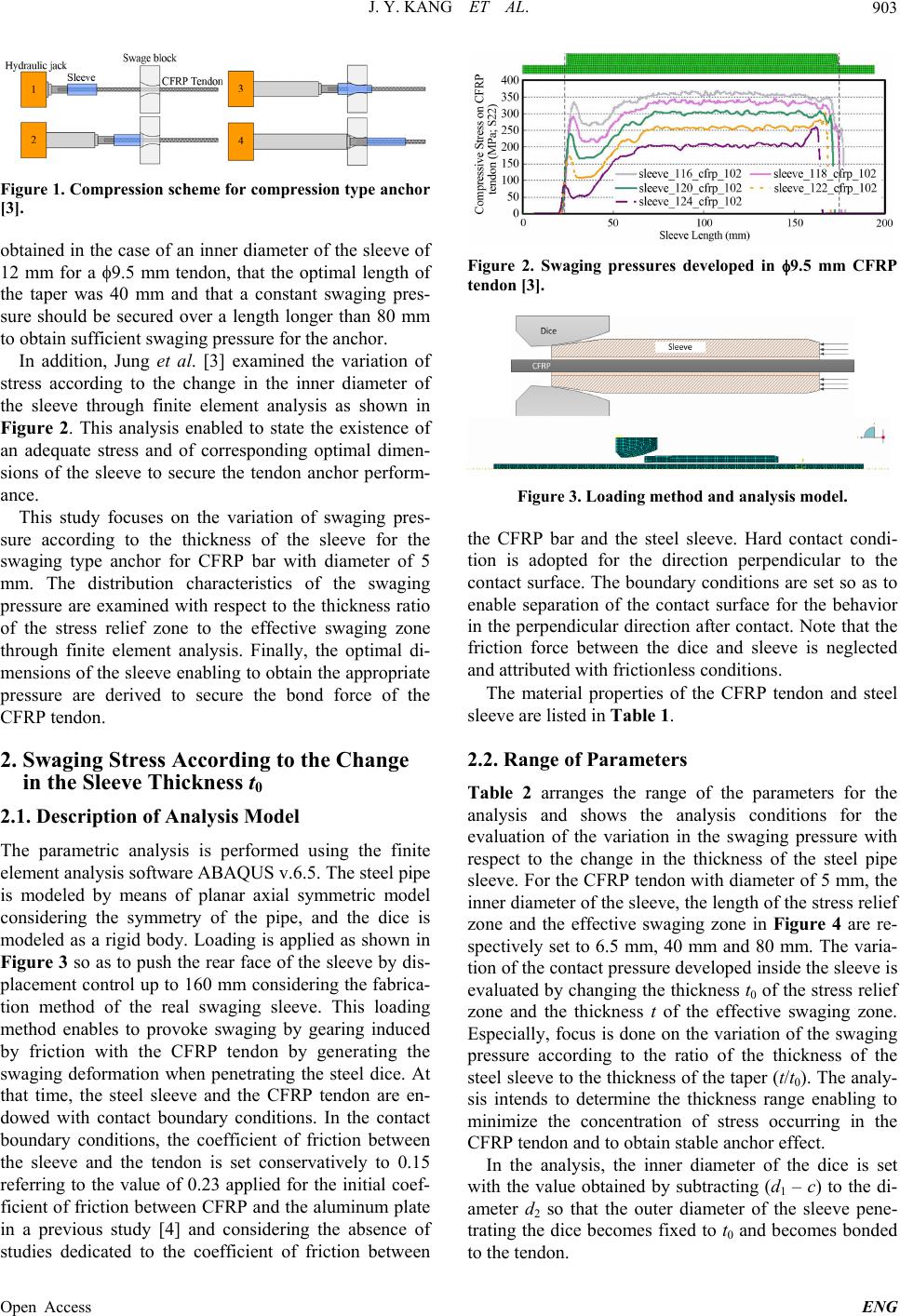
Figure 10. Comparison of mean pressure in sleeve accord-
ing to the variation of the inner diameter of sleeve.
with the inner diameter (d1) and the thickness ratio (t/t0)
of the steel pipe sleeve as parameters considering the
prestressing reinforcement using a CFRP tendon with
diameter of 5 mm. The results enabled to derive the fol-
lowing optimal dimensions of the sleeve achieving the
required bond performance without occurrence of slip of
the tendon in the sleeve.
(1) A constant pressure of approximately 450 MPa can
be obtained in the effective swaging zone when the
thickness ratio (t/t0) of the sleeve is larger than 1.1. Since
the pressure which is required to extrude the sleeve in-
creases with larger thickness ratio, the optimal value of
the thickness ratio app ears to be 1.1 considering the effi-
ciency of construction.
(2) Assuming a thickness ratio (t/t0) of 1.1, the varia-
tion of the inner diameter of the sleeve is seen to affect
the swaging pressure less than 10%. Accordingly, the
optimal value of the inner diameter of the sleeve should
be 5.5 mm to reduce the amount of steel and minimize
the pressure during the ex trusion.
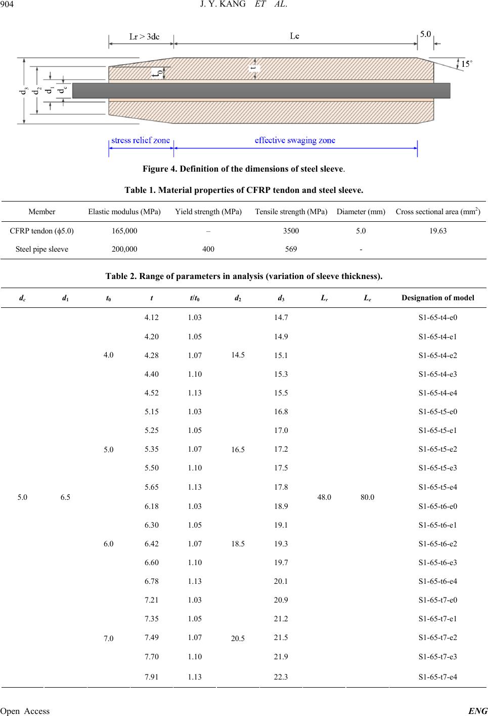
(3) For a dice with diameter of 16 mm and a sleeve
with thicknesses t0 = 5.5 mm and t = 6.1 mm, and inner
diameter d1 = 5.5 mm, the effective swaging pressure
developed in the sleeve takes value of about 440 MPa.
The corresponding bond force is approximately 104 kN
when the length of the effective swaging zone of the
sleeve is 80 mm. This value represents about 1.5 times
the rupture strength of 70 kN of the CFRP tendon with
diameter of 5 mm and indicates that sufficient bond
strength can be secured during prestressing. In order to
obtain a bond force comparable to the rupture strength of
the CFRP tendon, the length of the effective swaging
zone should run around 67.5 mm. The application of a
sleeve presenting a longer length of the effective swaging
zone will thus achieve sufficient bond performance.
Figure 11 illustrates the optimal dimensions of the
waging type sleeve based upon these requirements and s
Figure 11. Optimal dimensions of swaging type sleeve for
CFRP tendon with diame ter of 5 mm.
enables to secure the bond performance of the CFRP
tendon with diameter of 5 mm.
It should be noted that the optimal dimensions of the
sleeve derived in this study include uncertainties on the
actual bond behavior like the assumption of a conserva-
tive coefficient of friction between the steel sleeve and
the CFRP tendon. The need is thus to verify the bond
performance in the future by performing pull out tests
based upon the dimensions of the sleeve derived in this
study and to examine their site applicability.
5. Acknowledgements
This research was supported by grant from Strategic Re-
search Project (Development of Bridge Strengthening
Method using Prestressed FRP Composites) funded by
Korea Institute of Construction Technology.
REFERENCES
[1] N. Nordin and B. Talisten, “Concrete Beams Strength-
ened with Prestressed near Surface Mounted CFRP,”
Journal of Composites for Construction, Vol. 10, No. 1,
2006, pp. 60-68.
http://dx.doi.org/10.1061/(ASCE)1090-0268(2006)10:1(6
0)
[2] A. Hajihashemi, D. Mostofinejad and M. Azhari, “Inves-
tigation of RC Beams Strengthened with Prestressed
NSM CFRP Laminates,” Journal of Composites for Con-
struction, Vol. 15, No. 6, 2011, pp. 887-895.
http://dx.doi.org/10.1061/(ASCE)CC.1943-5614.0000225
[3] W. T. Jung, Y. H. Park and J. S. Park, “An Experimental
Study on Improving Anchor Performance for CFRP
Tendons,” American Concrete Institute, Vol. 275, 2011,
pp. 1-16.
[4] J. Schön, “Coefficient of Friction for Aluminum in Con-
tact with a Carbon Fiber Epoxy Composite,” Tribology
International, Vol. 37, No. 5, 2004, pp.395-404.
http://dx.doi.org/10.1016/j.triboint.2003.11.008
Open Access ENG