S. H. WANG ET AL.
62
SOPC Builder is responsible for the Nios II hardware
system construction, including selecting and connecting
components, determining the processor, configuring the
storage devices and designing the different types of in-
terface. SOPC Builder will generate the Nios II system,
the Quartus II add the system to the proj ect, fulfilling the
framework of the system and downloaded it to the target
board. SOPC Builder instores the Nios II hardware in-
formation in the .ptf file, the Nios II IDE can access sys-
tem hardware information by the .ptf file, and generate
the appropriate HAL system library and driver. Software
algorithm first debugs on a single-core system, and then
complements data exchange and communication between
the multicore, gradually debug ging successfully. After, if
necessary, you can use the C2H Compiler to conduct
hardware acceleration. Finally, the Nios II IDE will gen-
erate the Flash file to download to the target hardware
[4].
This is the complete development process of the SOPC
system.
3. Hardware Part
Three cores are used in this multi-core systems, The first
core completes recognition processing and judgment of
red lights and traffic signs with a red element, the second
core completes recognition processing and judgment of
yellow lights and traffic sign s with a yellow element, the
third core completes recognition processing and judg-
ment of green lights and traffic signs with a green ele-
ment as well as for the control of the peripheral response
devices. The image data read by the camera will be
shared data of the three cores, three cores will all do the
binarization processing and pattern recognition for dif-
ferent colors in the image, three cores have timing se-
quence and will take d ata exchange communications with
the third core to achieve effective control of the periph-
eral [5].
3.1. Building of the Hardware Platform
1) First, completing single-core system structures is
the Core part of the entire multi-core hardware platform.
Select IP cores required to add and connect for the sys-
tem in the SOPC. When the multi-core hardware plat-
form is completed, click the Generate button to generate
the Nios II system module. Add and configure the
phase-locked loop into the platform at last.
2) Then, we’ll finish completing the multi-core syste m
structures. Add the second and third core and clocks and
rename them on the basis of the previous single-core
systems. Then, add a mutex and a message buffer mem-
ory to achieve the communication between the three
cores. Finishing setting the connection of multi-core
shared buffer and adding the corresponding address, we
will get the three-core system [6 ].
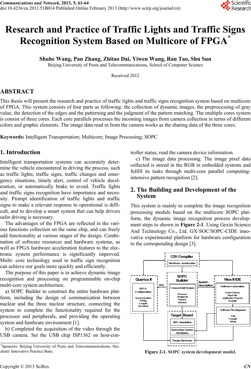
3.2. The Overall System Architecture As Shown
4. Software Part
This section mainly introduces the USB camera data ac-
quisition module, the image recognition and the
achievement of processing algorithms.
4.1. USB Camera Acquisition Modules
The hassel camera is used in this paper for video signal
acquisition. The video signal will be encoded to the for-
mat as prescribed by the image processing chip inside the
USB camera. Here we output the pixel values in RGB
format. Besides the head of the packet, the pixel values
of the main body of the packet are stored into the form of
"R, G , B, R, G, B ... ”. The camera resolution is 640 *
480. We do not need to process all the pixel values, but
to sample the image information from the acquisition.
We sample the data of each frame circularly, and store
into the two-dimensional array for the following proc-
essing. The system flow chart is to shown in Fig u r e 4 -1.
4.2. Camera Data Processing Module
First, the hardware system read the RGB values matrix
information of the image from the camera. The first step,
we change the RGB color space into the HSI color space,
Figure 3-1. Hardware system structure.
Copyright © 2013 SciRes. CN