Paper Menu >>
Journal Menu >>
 Communications and Network, 2013, 5, 1-4 doi:10.4236/cn.2013.51B001 Published Online February 2013 (http://www.scirp.org/journal/cn) Communication Technology and Application of Seismic Precursor Network Instrument Jianguo Wang, Wei Wang, Huiqin Yao, Xun Gao, Mingdong Zhang Earthquake Administration of Tianjin Municipality, Tianjin, China, 300201 Email: tjjgw@163.com Received 2012 ABSTRACT In this paper, the communication technology of seismic precursor network instrument is introduced, including instruc- tion format and returned information format of instrument login, status information acquisition, and current measured data acquisition. The remote monitoring alarm software is based on this technolog y, and also introduced that the struc- ture of monitoring information table, abnormal alarm index, and monitoring strategy. The application of the software raises instrument running rate and observation data quality. Keywords: Network Instrument; Communication Technology; Remote Monitoring Alarm 1. Introduction Through digital seismic observation network projects, Tianjin seismic precursor network, from network to the station, distributed database to station, IP to device can monitor and control precursor observation instrument remotely. Realized gathering instrument data and real- time monitoring instrument’s status and property, by which remote change the parameters and adjust the working status of instrument, and can control basic in- strument calibration [1-3]. During seismic precursor network instrument running, always following system halted, clock error and wrong data and so on, having a bad effect on instrument running rate and data quality. For this reason, according stipulation on geoscience observatory network in China, we compiled the software to monitor network instrument remotely and alarm by C#, to identify and solve problems in time and improve run- ning rate and data quality of instrument [1-3]. 2. Network Instrument Communication Technology Stipulation on geoscience observatory network in China is a network communication interface enacted for pre- cursor observation instrument. It detailed prescribes the precursor network instrument’s communication interface, device information, running function, data format, com- munication protocol and access security control protocol, etc. It is an essential communication protocol for network precursor instrument [1-3]. The data communication of client and instrument is conducted by Ethernet and Socket based on TCP/IP pro- tocol. Client sends request to instrument, realizes the control of instrument and exchange of data information. Instrument accepts and responds the instruction from client, then implements the co rresponding action to com- plete the data information exchange with client; instru- ment can be regard as server [1-3 ]. System. Net. Sockets namespace in C# provides re- lated class for writing network application programs like Socket, TcpClient, and Net Work Stream and so on. Socket class is used in management connection, to re- alize Berkeley sockets interface. TcpClient class is based on the Socket class, allows creating and using TCP con- nection. Net Work Stream class deals specifically with data stream of network form, receipts object parameter of Socket class, and operate network data access [1-3]. 2.1. Detect Instrument Network Status Using C# call ping command (ping -n 1 192.168.1.2) to detect connection of network, it is an easy way. In the output stream, “(0% loss)” indicates that the network is smooth, “Ping request could not find host" indicates that ping request could not find host, "Request timed out or (100% loss)” indicates ping request timed out. 2.2. Login Instrument Client and instrument establish connection through in- struction mode, according to user name and password authenticates iden tity [1-3]. Send instruction format: get /length+ID+lin+username Copyright © 2013 SciRes. CN 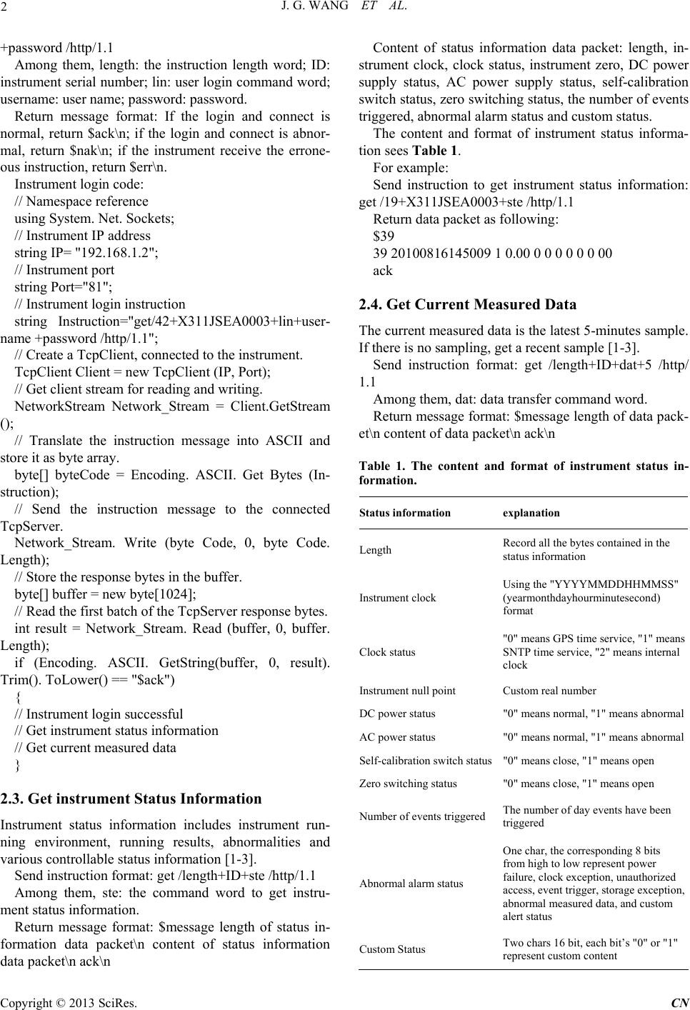 J. G. WANG ET AL. 2 +password /http/1.1 Among them, length: the instruction length word; ID: instrument serial number; lin: user login command word; username: user name; password: password. Return message format: If the login and connect is normal, return $ack\n; if the login and connect is abnor- mal, return $nak\n; if the instrument receive the errone- ous instruction, return $err\n. Instrument login code: // Namespace reference using System. Net. Sockets; // Instrument IP address string IP= "192.168.1.2"; // Instrument port string Port="81"; // Instrument login instruction string Instruction="get/42+X311JSEA0003+lin+user- name +password /http/1.1"; // Create a TcpClient, connected to the instrument. TcpClient Client = new TcpClient (IP, Port); // Get client stream for reading and writing. NetworkStream Network_Stream = Client.GetStream (); // Translate the instruction message into ASCII and store it as byte array. byte[] byteCode = Encoding. ASCII. Get Bytes (In- struction); // Send the instruction message to the connected TcpServer. Network_Stream. Write (byte Code, 0, byte Code. Length); // Store the response bytes in the buffer. byte[] buffer = new byte[1024]; // Read the first batch of the TcpServer response bytes. int result = Network_Stream. Read (buffer, 0, buffer. Length); if (Encoding. ASCII. GetString(buffer, 0, result). Trim(). ToLower() == "$ack") { // Instrument login successful // Get instrument status informatio n // Get current measured data } 2.3. Get instrument Status Information Instrument status information includes instrument run- ning environment, running results, abnormalities and various controllable status information [1-3]. Send instruction format: get /length+ID+ste /http/1.1 Among them, ste: the command word to get instru- ment status information. Return message format: $message length of status in- formation data packet\n content of status information data packet\n ack\n Content of status information data packet: length, in- strument clock, clock status, instrument zero, DC power supply status, AC power supply status, self-calibration switch status, zero switching status, the number of events triggered, abnormal alarm status and custom status. The content and format of instrument status informa- tion sees Table 1. For example: Send instruction to get instrument status information: get /19+X311JSEA0003+ste /http/1.1 Return data packet as following: $39 39 20100816145009 1 0.00 0 0 0 0 0 0 00 ack 2.4. Get Current Measured Data The current measured data is the latest 5-minutes sample. If there is no sampling, get a recent sample [1-3]. Send instruction format: get /length+ID+dat+5 /http/ 1.1 Among them, dat: data transfer command word. Return message format: $message length of data pack- et\n content of data packet\n ack\n Table 1. The content and format of instrument status in- formation. Status information explanation Length Record all the bytes contained in the status information Instrument clock Using the "YYYYMMDDHHMMSS" (yearmonthdayhourminutesecond) format Clock status "0" means GPS time service, "1" means SNTP time service, "2" means internal clock Instrument null point Custom real number DC power status "0" means normal, "1" means abnormal AC power status "0" means normal, "1" means abnormal Self-calibration switch status"0" means close, "1" means open Zero switching status "0" means close, "1" means open Number of events trigge red The number of da y ev e n t s h a v e b e e n triggered Abnormal alarm status One char, the corresponding 8 bits from high to low represent power failure, clock exception, unauthorized access, event trigger, storage exception, abnormal measured data, and custom alert status Custom Status Two chars 16 bit, each bit’s "0" or "1" represent custom content Copyright © 2013 SciRes. CN 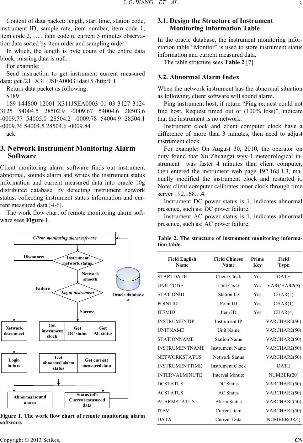 J. G. WANG ET AL. 3 Content of data packet: leng th, start time, station code, instrument ID, sample rate, item number, item code 1, item code 2, … , item code n, current 5 minutes observa- tion data sorted by item order and sampling order. In which, the length is byte count of the entire data block, missing data is null. For example: Send instruction to get instrument current measured data: get /21+X311JSEA0003+dat+5 /http/1.1 Return data packet as following: $189 189 144800 12001 X311JSEA0003 01 03 3127 3124 3125 54004.5 28502.9 -0009.67 54004.6 28503.6 -0009.77 54005.0 28504.2 -0009.78 54004.9 28504.1 -0009.76 54004.5 28504.6 -0009.84 ack 3. Network Instrument Monitoring Alarm Software Client monitoring alarm software finds out instrument abnormal, sounds alarm and writes the instrument status information and current measured data into oracle 10g distributed database, by detecting instrument network status, collecting instrument status information and cur- rent measured data [4-6]. The work flow chart of remote monitoring alarm soft- ware sees Figure 1. Figure 1. The work flow chart of remote monitoring alarm software. 3.1. Design the Structure of Instrument Monitoring Information Table In the oracle database, the instrument monitoring infor- mation table “Monitor” is used to store instrument status information and current measured data. The table structure sees Table 2 [7]. 3.2. Abnormal Alarm Index When the network instrument has the abnormal situation as following, client software will sound alarm. Ping instrument host, if return “Ping request could not find host, Request timed out or (100% loss)”, indicate that the instrument is no network. Instrument clock and client computer clock have a difference of more than 3 minutes, then need to adjust instrument clock. For example: On August 30, 2010, the operator on duty found that Xu Zhuangzi wyy-1 meteorological in- strument was faster 4 minutes than client computer, then entered the instrument web page 192.168.1.3, ma- nually modified the instrument clock and restarted it. Note: client computer calibrates inner clock through time server 192.168.1.4. Instrument DC power status is 1, indicates abnormal presence, such as: DC power failure. Instrument AC power status is 1, indicates abnormal presence, such as: AC power failure. Table 2. The structure of instrument monitoring informa- tion table. Field English Name Field Chinese Name Prime Key Field Type STARTDATE Client Clock Yes DATE UNITCODE Unit Code Yes VARCHAR2(5) STATIONID Station ID Yes CHAR(5) POINTID Point ID Yes CHAR(1) ITEMID Item ID Yes CHAR(4) INSTRUMENTIP Instrument IP VARCHAR2(50) UNITNAME Unit Name VARCHAR2(50) STATIONNAME Station Name VARCHAR2(50) INSTRUMENTNAMEInstrument Name VARCHAR2(50) NETWORKSTATUS Network Status VARCHAR2(50) INSTRUMENTTIMEInstrument Clock DATE INTERVALMINUTEInterval Minute NUMBER(20) DCSTATUS DC Status VARCHAR2(50) ACSTATUS AC Status VARCHAR2(50) ALARMSTATUS Alarm Status VARCHAR2(50) ITEM Current Item VARCHAR2(50) DATA Current Data NUMBER(38,4) Copyright © 2013 SciRes. CN 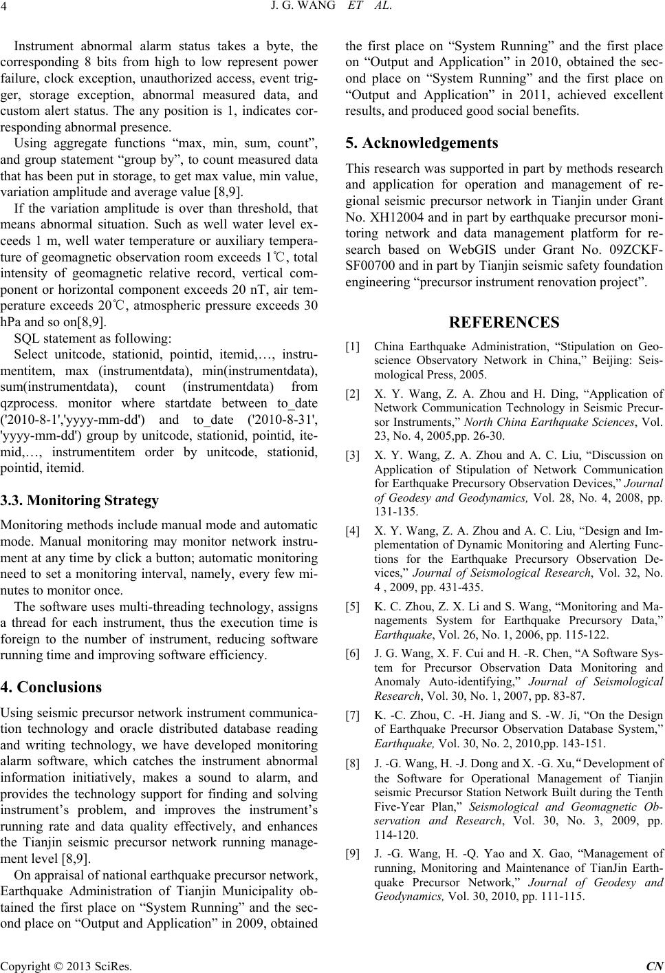 J. G. WANG ET AL. Copyright © 2013 SciRes. CN 4 Instrument abnormal alarm status takes a byte, the corresponding 8 bits from high to low represent power failure, clock exception, unauthorized access, event trig- ger, storage exception, abnormal measured data, and custom alert status. The any position is 1, indicates cor- responding abnormal presence. Using aggregate functions “max, min, sum, count”, and group statement “group by”, to count measured data that has been put in storage, to get max value, min value, variation amplitude and average value [8,9]. If the variation amplitude is over than threshold, that means abnormal situation. Such as well water level ex- ceeds 1 m, well water temperature or auxiliary tempera- ture of geomagnetic observation room exceeds 1℃, total intensity of geomagnetic relative record, vertical com- ponent or horizontal component exceeds 20 nT, air tem- perature exceeds 20℃, atmospheric pressure exceeds 30 hPa and so on[8,9]. SQL statement as following: Select unitcode, stationid, pointid, itemid,…, instru- mentitem, max (instrumentdata), min(instrumentdata), sum(instrumentdata), count (instrumentdata) from qzprocess. monitor where startdate between to_date ('2010-8-1','yyyy-mm-dd') and to_date ('2010-8-31', 'yyyy-mm-dd') group by unitcode, stationid, pointid, ite- mid,…, instrumentitem order by unitcode, stationid, pointid, itemid. 3.3. Monitoring Strategy Monitoring methods include manual mode and automatic mode. Manual monitoring may monitor network instru- ment at any time by click a button; automatic monitoring need to set a monitoring interval, namely, every few mi- nutes to monitor once. The software uses multi-threading technology, assigns a thread for each instrument, thus the execution time is foreign to the number of instrument, reducing software running time and improving software efficiency. 4. Conclusions Using seismic precursor network instrument communica- tion technology and oracle distributed database reading and writing technology, we have developed monitoring alarm software, which catches the instrument abnormal information initiatively, makes a sound to alarm, and provides the technology support for finding and solving instrument’s problem, and improves the instrument’s running rate and data quality effectively, and enhances the Tianjin seismic precursor network running manage- ment level [8,9]. On appraisal of national earthquake precursor network, Earthquake Administration of Tianjin Municipality ob- tained the first place on “System Running” and the sec- nd place on “Output and Application” in 2009, obtained the first place on “System Running” and the first place on “Output and Application” in 2010, obtained the sec- ond place on “System Running” and the first place on “Output and Application” in 2011, achieved excellent results, and produced good social benefit s. o 5. Acknowledgements This research was supported in part by methods research and application for operation and management of re- gional seismic precursor network in Tianjin under Grant No. XH12004 and in part by earthquake precursor moni- toring network and data management platform for re- search based on WebGIS under Grant No. 09ZCKF- SF00700 and in part by Tianjin seismic safety foundation engineering “precursor instrument renovation project”. REFERENCES [1] China Earthquake Administration, “Stipulation on Geo- science Observatory Network in China,” Beijing: Seis- mological Press, 2005. [2] X. Y. Wang, Z. A. Zhou and H. Ding, “Application of Network Communication Technology in Seismic Precur- sor Instruments,” North China Earthquake Sciences, Vol. 23, No. 4, 2005,pp. 26-30. [3] X. Y. Wang, Z. A. Zhou and A. C. Liu, “Discussion on Application of Stipulation of Network Communication for Earthquake Precursory Observation Devices,” Journal of Geodesy and Geodynamics, Vol. 28, No. 4, 2008, pp. 131-135. [4] X. Y. Wang, Z. A. Zhou and A. C. Liu, “Design and Im- plementation of Dynamic Monitoring and Alerting Func- tions for the Earthquake Precursory Observation De- vices,” Journal of Seismological Research, Vol. 32, No. 4 , 2009, pp. 431-435. [5] K. C. Zhou, Z. X. Li and S. Wang, “Monitoring and Ma- nagements System for Earthquake Precursory Data,” Earthquake, Vol. 26, No. 1, 2006, pp. 115-122. [6] J. G. Wang, X. F. Cui and H. -R. Chen, “A Software Sys- tem for Precursor Observation Data Monitoring and Anomaly Auto-identifying,” Journal of Seismological Research, Vol. 30, No. 1, 2007, pp. 83-87. [7] K. -C. Zhou, C. -H. Jiang and S. -W. Ji, “On the Design of Earthquake Precursor Observation Database System,” Earthquake, Vol. 30, No. 2, 2010,pp. 143-151. [8] J. -G. Wang, H. -J. Dong and X. -G. Xu,“Development of the Software for Operational Management of Tianjin seismic Precursor Station Network Built during the Tenth Five-Year Plan,” Seismological and Geomagnetic Ob- servation and Research, Vol. 30, No. 3, 2009, pp. 114-120. [9] J. -G. Wang, H. -Q. Yao and X. Gao, “Management of running, Monitoring and Maintenance of TianJin Earth- quake Precursor Network,” Journal of Geodesy and Geodynamics, Vol. 30, 2010, pp. 111-115. |