Paper Menu >>
Journal Menu >>
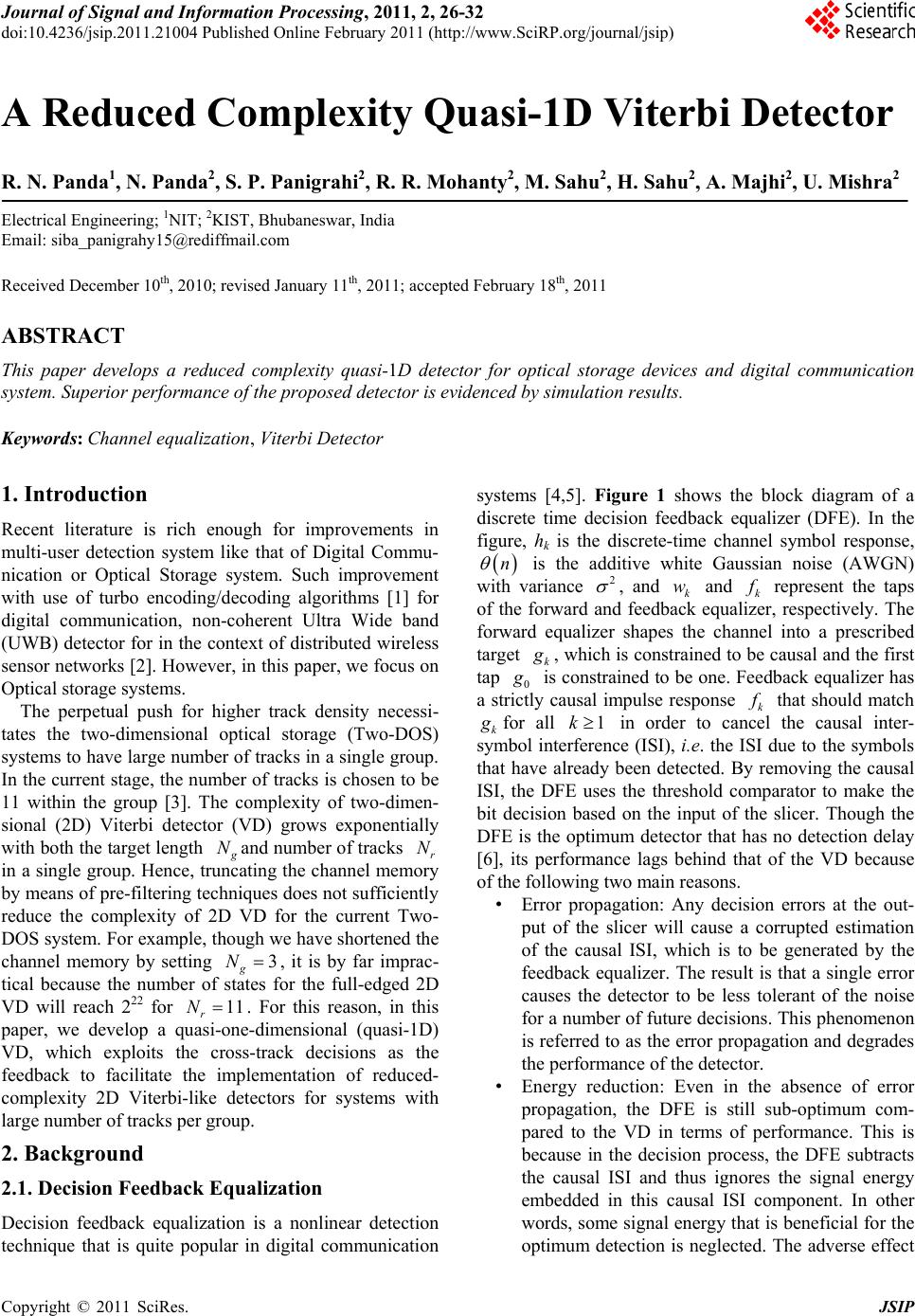 Journal of Signal and Information Processing, 20 11 , 2, 26 - 32 doi:10.4236/jsip.2011.21004 Published Online February 2011 (http://www.SciRP.org/journal/jsip) Copyright © 2011 SciRes. JSIP A Reduced Complexity Quasi-1D Viterbi Detector R. N. Panda1, N. Panda2, S. P. Panigrahi2, R. R. Mohanty2, M. Sahu2, H. Sahu2, A. Majhi2, U. Mishra2 Electrical Engineering; 1NIT; 2KIST, Bhubaneswar, India Email: siba_panigrahy15@rediffmail.com Received December 10th, 2010; revised January 11th, 2011; accepted February 18th, 2011 ABSTRACT This paper develops a reduced complexity quasi-1D detector for optical storage devices and digital communication system. Superior performance of the proposed detector is evidenced by simulation results. Keywords: Channel equalization, Viterbi Detector 1. Introduction Recent literature is rich enough for improvements in multi-user detection system like that of Digital Commu- nication or Optical Storage system. Such improvement with use of turbo encoding/decoding algorithms [1] for digital communication, non-coherent Ultra Wide band (UWB) detector for in the context of distributed wireless sensor networks [2]. However, in this paper, we focus on Optical storage systems. The perpetual push for higher track density necessi- tates the two-dimensional optical storage (Two-DOS) systems to have large number of tr acks in a single group. In the current stage, the number of tracks is chosen to be 11 within the group [3]. The complexity of two-dimen- sional (2D) Viterbi detector (VD) grows exponentially with both the target length g Nand number of tracks r N in a single group. Hen ce, truncating the channel memory by means of pre-filtering techniques does not sufficiently reduce the complexity of 2D VD for the current Two- DOS system. For example, though we have shortened the channel memory by setting 3 g N, it is by far imprac- tical because the number of states for the full-edged 2D VD will reach 222 for 11 r N. For this reason, in this paper, we develop a quasi-one-dimensional (quasi-1D) VD, which exploits the cross-track decisions as the feedback to facilitate the implementation of reduced- complexity 2D Viterbi-like detectors for systems with large number of tracks per group. 2. Background 2.1. Decision Feedback Equalization Decision feedback equalization is a nonlinear detection technique that is quite popular in digital communication systems [4,5]. Figure 1 shows the block diagram of a discrete time decision feedback equalizer (DFE). In the figure, hk is the discrete-time channel symbol response, n is the additive white Gaussian noise (AWGN) with variance 2 , and k w and k f represent the taps of the forward and feedback equalizer, respectively. The forward equalizer shapes the channel into a prescribed target k g , which is constrained to be causal and the first tap 0 g is constrained to be one. Feedback equalizer has a strictly causal impulse response k f that should match k g for all 1k in order to cancel the causal inter- symbol interference (ISI), i.e. the ISI due to the symbols that have already been detected. By removing the causal ISI, the DFE uses the threshold comparator to make the bit decision based on the input of the slicer. Though the DFE is the optimum detector that has no detection delay [6], its performance lags behind that of the VD because of the following two main reasons. • Error propagation: Any decision errors at the out- put of the slicer will cause a corrupted estimation of the causal ISI, which is to be generated by the feedback equalizer. The result is that a single error causes the detector to be less tolerant of the noise for a number of future decisions. This phenomenon is referred to as th e error propagation and degrades the performance of the detector. • Energy reduction: Even in the absence of error propagation, the DFE is still sub-optimum com- pared to the VD in terms of performance. This is because in the decision process, the DFE subtracts the causal ISI and thus ignores the signal energy embedded in this causal ISI component. In other words, some signal energy that is beneficial for the optimum detection is neglected. The adverse effect 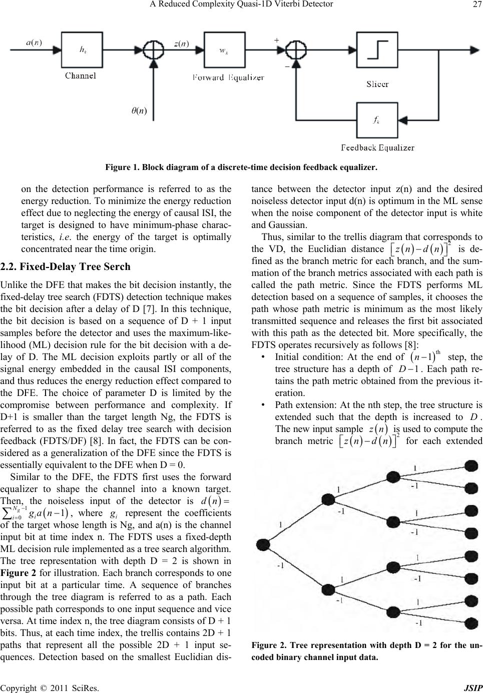 A Reduced Complexity Quasi-1D Viterbi Detector Copyright © 2011 SciRes. JSIP 27 θ(n) Figure 1. Block diagram of a discrete-time decision feedback equalizer. on the detection performance is referred to as the energy reduction. To minimize the energy reduction effect due to neglecting the energy of causal ISI, the target is designed to have minimum-phase charac- teristics, i.e. the energy of the target is optimally concentrated near the time origin. 2.2. Fixed-Delay Tree Serch Unlike the DFE that makes the bit decision instantly, the fixed-delay tree search (FDTS) detection technique makes the bit decision after a delay of D [7]. In this technique, the bit decision is based on a sequence of D + 1 input samples before the detector and uses the maximum-like- lihood (ML) decision rule for the bit decision with a de- lay of D. The ML decision exploits partly or all of the signal energy embedded in the causal ISI components, and thus reduces the energy reduction effect compared to the DFE. The choice of parameter D is limited by the compromise between performance and complexity. If D+1 is smaller than the target length Ng, the FDTS is referred to as the fixed delay tree search with decision feedback (FDTS/DF) [8]. In fact, the FDTS can be con- sidered as a generalization of the DFE since the FDTS is essentially equivalent to the DFE when D = 0. Similar to the DFE, the FDTS first uses the forward equalizer to shape the channel into a known target. Then, the noiseless input of the detector is dn 1 01 g N i iga n , where i g represent the coefficients of the target whose length is Ng, and a(n) is the channel input bit at time index n. The FDTS uses a fixed-depth ML decision rule implemented as a tree search algorithm. The tree representation with depth D = 2 is shown in Figure 2 for illustration. Each branch corresponds to one input bit at a particular time. A sequence of branches through the tree diagram is referred to as a path. Each possible path corresponds to one input sequence and vice versa. At time index n, the tree diagram consists of D + 1 bits. Thus, at each time index, the trellis contains 2D + 1 paths that represent all the possible 2D + 1 input se- quences. Detection based on the smallest Euclidian dis- tance between the detector input z(n) and the desired noiseless detector input d(n) is optimum in the ML sense when the noise component of the detector input is white and Gaussian. Thus, similar to the trellis diagram that corresponds to the VD, the Euclidian distance 2 zn dn is de- fined as the branch metric for each branch, and the sum- mation of the branch metrics associated with each path is called the path metric. Since the FDTS performs ML detection based on a sequence of samples, it chooses the path whose path metric is minimum as the most likely transmitted sequence and releases the first bit associated with this path as the detected bit. More specifically, the FDTS operates recursively as follows [8]: • Initial condition: At the end of th 1n step, the tree structure has a depth of 1D. Each path re- tains the path metric obtained from the previous it- eration. • Path extension: At the nth step, the tree structure is extended such that the depth is increased to D. The new input sample zn is used to compute the branch metric 2 z ndn for each extended Figure 2. Tree representation with depth D = 2 for the un- coded binary channel input data.  A Reduced Complexity Quasi-1D Viterbi Detector Copyright © 2011 SciRes. JSIP 28 branch. To compute dn for each extended branch, the possible channel input bit sequence consists of the preceding 1 g N input bits lying on the path leading to that extended branch. If the channel memory 1 g N exceeds the detection delay D, the already detected bits are also used to compute dn. • Path selection: After computing all the path metrics for the extended paths, the first bit of the path that has the smallest path metric is selected and released as the detected bit. Then, half of the total paths that are incompatible with the detected bit are discarded. As a result, the tree structure that remains has a depth of 1D. As time progresses, the root node moves along the ML path and a fixed-size identical tree structure is main- tained at each time index. Therefore, the complexity of the FDTS is kept constant for each time index. Similar to the VD, the ML decision rule makes the FDTS unduly complicated if D is large. An efficient and simple re- alization of the FDTS for systems using run length- lim- ited (RLL) (1; k) codes can be found in [9,10]. 2.3. Sequence Detection with Local Feedback Many detection techniques with sequence feedback, such as the DFE and FDTS/DF, use the detected bits as the input of the feedback equalizer, resulting in the error propagation problem. Nevertheless, this problem can be reduced by resorting to local feedback [11,12]. The local feedback is based on the trellis structure, and uses the path memory associated with the current state instead of the past decisions to estimate the causal ISI. The local feedback guarantees that the branch metric of the correct path is the ML metric, as long as it is discarded in favor of some incorrect path [11]. As a result, it improves the performance of those detectors with sequence feedback at the price of requiring a large memory to store paths associated with each state. 3. Quasi-1D Viterbi Detector 3.1. Complexity of 2D VD 2D PR equalization to shape the 2D channel into a known 2D target with contro lled ISI and intertrack inter- ference (ITI). These controlled ISI and ITI are left to be handled by the 2D VD. The noiseless input of the 2D VD is given by 1 01 g N i i dn gan , where, i g is the target matrix whose length is Ng, and a(n) is the chann el input vector at time index n. As indicated earlier, the complexity of 2D VD grows exponentially with both the target length Ng and number of tracks r N in a single group. For a better understanding, the trellis structure for the case of target length 3 g N and number of tracks per group 2 r N is shown in Figure 3. In this figure, the ‘+’ and ‘ ’ represent the bits ‘+ 1’ and ‘1’, r espec- tively. The trellis is assumed to start at the node S0, and then becomes steady at instant 3n (i.e. g nN ). Here, the labels of states represent the channel memory and number of tracks per groups associated with the paths that pass through these states. At time index n, each state consists of 1 rg NN bits. Thus, at each time index, the trellis contains 1 2rg NN states. At time index n, each branch specifies the channel memory associated with the state that the branch originates from and the possible channel input vector _a(n). Therefore, each branch corresponds to one possible noiseless detector input 1 01 g N i i dn gan . For the binary channel input bit, each state possesses 2r N incoming and 2r Noutgoing branches and thus there are totally 2rg N Nincoming and 2rg N Nof outgoing branches for each time index of the trellis. In Figure 3, it is clear that even in this simple 2D case, the trellis of 2D case is much more complicated than the one-dimensional (1D) case though the target length is the same. Thus, the practical implementation of the 2D Vi- terbi-like detector for large Nr also requires the signifi- cant reduction of the complexity arising from the Figure 3. Trellis structure for a channel with Ng = 3 and Nr = 2.  A Reduced Complexity Quasi-1D Viterbi Detector Copyright © 2011 SciRes. JSIP 29 cross-track direction. In [13], a technique using the Viterbi detector track-by-track, as well as the decision feedback to estimate the ITI between tracks was pro- posed. We call this detector the DFE-VD. It uses a set of sub-2D VDs, each corresponding to one track. In the bit decision process for a given track, the known bits just above (or below) the current track are used as the feed- back to calculate par t of the ITI. Th ese known bits can be previously detected bits, or can be zeros if the upper (or lower) track is the guard-band. The branch metric is then computed by subtracting the effect of these known bits. However, in this track-by- track technique, the ITI from either only the upper track(s) or only the lower track(s) estimated, and the re- maining ITI estimations are still dependent on the trellis states. As a result, the number of states should be larger than that of 1D VD with the same target length. More- over, this redundant complexity will not benefit per- formance much since the detector makes the detection based still only on the input samples from the current single track. An improved detector is the stripe-wise Vi- terbi detector (SWVD) [3,14]. This detector consists of a set of sub-2D VDs, each dealing with one stripe that consists of a limited number of tracks. The number of stripes is equal to that of tracks in a single group. The preliminary decisions from one sub-2D VD is used for estimating the ITI in the next sub-2D VD, which is shifted up (or down) by one track. This procedure is con- tinued for all the stripes and the full procedure from bot- tom to top (or top to bottom) of the group is considered to be one iteration. Note that at least two iterations are required in order to estimate the ITI from both upper and lower tracks. Unlike the DFE-VD that resorts to the trel- lis states to estimate the ITI from the lower (or upper) track(s), the SWVD uses the preliminary decisions from the previous iteration to estimate the ITI from the lower (or upper) track(s). This additional decision feedback not only reduces the complexity but also improves the per- formance compared with the DFE-VD since its decisions exploit the input information from both upper and lower track(s) as well as that from current. However, the use of iterations increases complexity as well as latency. Our new proposal, whereas, is a non-iterative reduced-com- plexity detector that is applicable to any 2D system. 3.2. Causal ITI Target In this subsection, we introduce the causal ITI target as a starting point for the development of our reduced-com- plexity 2D Viterbi-like detectors. Conventionally, the causal and anticausal ISI are referred to as the ISI from the past and future bit decisions, respectively [6]. Simi- larly, we refer to the causal and anticausal ITI as the ITI resulting from the lower and upper tracks, respectively. The concept of causal ITI was first used in the multi- channel DFE [15]. Similar as shown in Figure 1, this multi-channel DFE consists of a multi-channel forward filter, a multi-channel feedback filter, and a decision block. The multi-channel forward filter is designed to constrain the channel to be causal ISI and ITI. The multi- channel feedback filter is designed to remove the causal ISI based on the previous bit decisions. The causal ITI is left to be handled by the decision block. Motivated by this, we propose the causal ITI target such that the 2D target matrices are constrained to be the right triangular matrices. It should be noted that this target is the basis for the development of our reduced-complexity 2D Vi- terbi-like detectors. As a starting point for our develop- ment, we first examine the suitability of the causal ITI target in Two-DOS. Figure 4 shows the performance of full-edged 2D VD for four different targets when 5 r N and target length 3 g N. In the figure, the di- agonal elements of G0 in the causal ITI target are con- strained to be 1s to avoid trivial solutions of the target and equalizer. We use a fixed 2D target with elements 12 and 2D monic constrained target, which are rea- sonable targets described in the last chapter for Two DOS, as reference targets. Note that we impose a sym- metry constraint, which constrains all the tracks within the same group to suffer the same amount of ITI, in the design of the 2D monic constrained target. In other words, after the finite length equalizer, all the tracks within the same group ideally suffer the same amount of ITI. However, due to the presence of guard-bands serv- ing as boundaries of the group, before the finite length equalizer, not all the tracks suffer the same amount of ITI. In addition, the 2D monic constrained target only allows ITI from adjacent tracks. Therefore, the symmetry con- straint will burden the design of finite length equalizer and result in residual ISI and ITI. Figure 4. BER performance for different target constraints.  A Reduced Complexity Quasi-1D Viterbi Detector Copyright © 2011 SciRes. JSIP 30 Note that the causal ITI target does not have this symmetry constraint, and allows ITI not only from the adjacent tracks. Therefore, compared with the 2D monic constrained target, the causal ITI target burdens th e finite length equalizer less and is expected to achieve better performance. From Figure 4, it is shown that the causal ITI target outperforms all the targets at every SNR. This result indicates that it is reasonable to use the causal ITI target for Two-DOS. More importantly, based on this target, we propose some reduced-complexity 2D Viter- bi-like detectors that are quite different from DFEVD and SWVD since the latter two detectors suffer ITI from both lower and upper tracks. 3.3. Principle of Quasi-1D VD Since the causal ITI target contains ITI only from the lower tracks, the bits in the upper tracks will not affect the desired output. Based on this idea, a set of 1D VDs are used to detect the bits, each deals with one track. More specifically, as shown in Figure 5, the first 1D VD that deals with the lowest track is processed with no de- lay and the bits are detected after a delay D. The second 1D VD that deals with the second lowest track is proc- essed with the delay D in order to use the detected bits from the lowest track to estimate all the ITI in the second lowest track. The third 1D VD that deals with the third lowest track is processed with a delay D after the second 1D VD, and the detected bits from the lowest two tracks are used to estimate the ITI in the third lowest track. This procedure continues for all the tracks. Since the bits de- tection does not need to consider the interference from the upper tracks, this detector is distinct from the DFE-VD and SWVD. Compared with the DFE-VD, this detector has less computational complexity since fewer states are needed for bit detection. More importantly, the quasi-1D VD has better BER performance since it uses all, while DFE-VD uses part, of the input information that is needed in the cross-track direction. As illustrated in Figure 6, the quasi-1D VD outperforms the DFE-VD significantly no matter what target is chosen for the DFE-VD. Compared with the SWVD, as mentioned pre- viously, it has much lower complexity since it has no iterative procedures. Link with QR Detector Our quasi-1D VD is developed for the Two-DOS sys- tem, which is a multiple-input multiple-output system having a large temporal span of the channel. Obviously, this quasi-1D VD is applicable to multiple-input multi- ple-output systems having an arbitrary temporal span of the channel. In many wireless communication systems, the multiple-input multiple-output channel is assumed to be at-fading [16,17], i.e. the temporal span 1 h N . In such systems, the channel is characterized by a matrix, Figure 5. Principle of the quasi-1D VD. The solid lines rep- resent the input and output of sub-VDs, the dashed lines represent the feedback coming from the output of the pre- vious sub-VDs. Figure 6. Performance comparison of different detection techniques. instead of a sequence of matrices in the Two-DOS sys- tem. Let 1 N and 2 N represent the number of transmit and receive antennas, respectively, in multiple-input multiple-output wireless communication systems. Then, the channel output vector at a given time is given by zHa (1) Where, z and a are the (21N) channel output vec- tor, and (11N ) channel input vector, respectively, H is the (21 NN ) at-fading channel matrix. For the sake of simplicity, the time index is ignored here. Then, QR de- composition of the channel matrix yields QRH , where Q is an (21 NN ) ortho-normal matrix con- structed to make the (11 NN ) matrix R right triangu- lar [19]. Pre-multiplying the channel output vector z with H Q, the resulting vector ˆ z is given by ˆH zQzRa (2) Note that if the noise in z is additive white Gaussian noise (AWGN), the noise in ˆ z remains AWGN since H QQ is an (11 NN ) identity matrix. Comparing R with the causal ITI target discussed in the previous sub- section, we find that R can be seen as a special case of  A Reduced Complexity Quasi-1D Viterbi Detector Copyright © 2011 SciRes. JSIP 31 causal ITI targets. Then, like the quasi-1D VD, the first element from the bottom of the channel input vector a is first detected. The detected element is used to estimate interferences for the detection of the second element from the bottom of a. This procedure continues until all the elements in a are detected. This detector is commonly referred to as the QR de- tector and has been investigated in multiple-input multi- ple-output at-fading channels [19-21]. The QR detector is also applicable in multiple-input multiple-output or- thogonal frequency division multiplexing (MIMO-OFDM) systems [20,22], since the channel at each sub-carrier of MIMO-OFDM systems is considered as a multiple-input multiple-output at-fading channel. Note that our pro- posed quasi-1D VD is suitable for any multiple-input multiple-output channel with arbitrary positive h N, while the QR detector is only applicable for multi- ple-input multiple-output at-fading channel, i.e. 1 h N . Therefore, the QR detector is considered as a special case of our proposed quasi-1D VD. 4. Performance of 1D VD As shown in Figure 5, though the quasi-1D has much lower complexity than the DFE-VD and SWVD, it causes significant detraction from optimality. We con- sider three factors that affect the performance of quasi- 1D VD: target length, error propagation and energy re- duction. In Figure 7, “L4” and “L5” represent that the lengths of targets are four and five, respectively. Other- wise, the length of target is three. “No EP” means detec- tors without suffering error propagation. In simulation, “No EP” is achieved by use of correct input bits to esti- mate ITI. The length of the equalizer is 31 in all the simulations. As illustrated in Figure 7, the BER per- formance is not significantly improved by increasing the target length. Further investigation shows that all the elements in target matrices 3 g and 4 g approach zero, therefore confirming that there is no need to increase the channel memory beyond two. Figure 7 also shows that the error propagation degrades performance by 1 dB for BER is 4 10. Thus, the energy reduction should be the dominant factor that degrades the performa nce. 5. Conclusions In this paper, we have first briefly reviewed prior work on the detectors with sequence feedback. Then, by con- straining the target with causal ITI, we have developed a quasi-1D VD, which uses a computationally efficient technique whose complexity, grows only linearly with the number of tracks. This is a significant complexity reduction compared to the conventional 2D VD whose complexity grows exponentially with the number of tracks. We have shown that the quasi-1D VD improves Figure 7. BER performance of quasi-1D VD with different target lengths. over the DFE-VD and SWVD in terms of complexity. Further, we have shown that the widely known QR de- tector is a special case of our proposed quasi-1D VD. However, we have found that the quasi-1D VD still causes significant detraction from optimality in the Two-DOS system. Therefore, effective compensation techniques are needed to ensure reliable data recovery. To achieve this goal, we have investigated the factors that might degrade the performance. Our simulation re- sults implied that the energy reduction is the dominant factor that degrades the performance of the quasi-1D VD. Therefore, in the next chapter, we develop some effective techniques to reduce the effect of this energy reduction problem. In addition, the effect of error propagation still needs to be minimized since it degrades the performance by roughly 1 dB when BER is 4 10. However, increas- ing the target length beyond three is of no practical value for the Two-DOS system since it hardly improves the performance while introducing excessive complexity. REFERENCES [1] S. V. Halunga, N. Vizireanu and O. Fratu, “Imperfect Cross-Corelation and Amplitude Balance Effects on Con- Ventional Multiuser Decoder with Turbo Encoding,” Digital Signal Processing, Vol. 20, No. 1, 2010, pp. 191- 200. doi:10.1016/j.dsp.2009.05.007 [2] B. Li, et al., “A Novel Parzen Probabilistic Neural Net- work based Non-coherent Detection Algorithm for Dis- tributed Ultra-wideband Sensors,” Journal of Network and Computer Applications, 2010, In Press. [3] A. H. J. Immink, et al., “Signal processing and coding for two-dimensional optical stora ge, ” Proceeding of the IEEE Global Telecommunications Conference, San Francisco, December 2003, pp. 3904-3908. [4] M. E. Austin, “Decision-feedback Equalization for Digi-  A Reduced Complexity Quasi-1D Viterbi Detector Copyright © 2011 SciRes. JSIP 32 tal Communication over Dispersive Channels,” Technol- ogy Report 437, MIT Lincoln Lab, Lexington, MA, Aug. 1967. [5] C. A. Belfiore and J. H. Park, “Decision Feedback Equali- zation,” Proceeding of the IEEE, Vol. 67, No. 8, 1979, pp. 1143-1156. doi:10.1109/PROC.1979.11409 [6] J. W. M. Bergmans, “Digital Baseband Transmission and Recording,” Kluwer Academic Publishers, Boston, 1996. [7] K. Abend and B. D. Fritchman, “Statistical Detection for Communication Channels with Intersymbol Interference,” Proceeding of the IEEE, Vol. 58, No. 5, 1970, pp. 779-785. doi: 10.1109/PROC.1970.7732 [8] J. Moon and L. R. Carley, “Performance Comparison of Detection Methods in Magnetic Recording,” IEEE Transaction, Vol. 26, No. 6, 1990, pp. 3155-3172. doi: 10.1109/20.102903 [9] J. G. Kenney, L. R. Carley and R. W. Wood, “Multi-level Decision Feedback Equalization for Saturation Re- cording,” IEEE Transaction, Vol. 29, No. 3, 1993, pp. 2160-2171. doi:10.1109/20.221040 [10] G. Mathew, B. F. Boroujeny and R. W. Wood, “Design of Multilevel Decision Feedback Equalizers,” IEEE Trans- action,” Vol. 33, No. 6, 1997, pp. 4528-4542. doi: 10.1109/20.649891 [11] V. M. Eyuboglu and S. U. H. Qureshi, “Reduced-state Sequence Estimation with Set Partitioning and Decision Feedback,” IEEE Transaction on Communications, Vol. COM-36, No. 1, 1988, pp. 13-20. doi:10.1109/26.2724 [12] A. D. Hallen and C. Heegard, “Delayed deci- sion-feedback sequence estimation,” IEEE Transaction on Communications, Vol. COM-37, No. 5, 1989, pp. 428-436. doi: 10.1109/26.24594 [13] J. F. Hea nue, K. Gurkan and L. Hesselink, “Decision Feedback Viterbi Detector for Page-Access Optical Memories,” U. S. Patent 5740184, April 14, 1998. [14] W. Coene, “Two Dimensional Optical storage,” Pro- ceeding of the International Conference on Optical Data Storage, Vancouver, May 2003, pp. 90-92. [15] S. Gopalaswamy and B. V. K. V. Kumar, “Multi-channel Decision Feedback Equalizer for High Track Density in Optical Recording," Optical Engineering, Vol. 35, No. 8, 1996, pp. 2386-2395. doi:10.1117/1.600812 [16] G. J. Foschini and M. J. Gans, “On Limits of Wireless Communications in a Fading Environment When Using Multiple Antennas,” Wireless Personal Communications, Vol. 6, No. 3, 1998, pp. 311-335. doi:10.1023/A:100 8889222784 [17] I. E. Telatar, “Capacity of Multi-antenna Gaussian Chan- nels,” European Transactions on Telecommunications, Vol. 10, No. 6, 1999, pp. 585-595. doi:10.1002/ett.44601 00604 [18] D. G. Manolakis, V. K. Ingle and S. M. Kogon, “Statisti- cal and Adaptive Signal Processing: Spectral Estimation, Signal Modeling, Adaptive Filtering and Array Process- ing,” McGraw-Hill, New York, 2000. [19] M. O. Damen, K. A.-Meraim and S. Burykh, “Iterative QR Detection for BLAST,” Wireless Personal Commu- nications, Vol. 19, No. 3, 2001, pp. 179-191. doi:10.1023/ A:1012514205 925 [20] D. Wubben, R. Bohnke, V. Kuhn and K. D. Kammeyer, “MMSE Extension of V-BLAST based on Sorted QR Decomposition,” Proceeding of the IEEE International Conference on Vehicles Technology, Orlando, May 2003, pp. 508-512. |