World Journal of Engineering and Technology, 2013, 1, 39-48
Published Online November 2013 (http://www.scirp.org/journal/wjet)
http://dx.doi.org/10.4236/wjet.2013.13007
Open Access WJET
39
Progressive Collapse of Steel Frames
Kamel Sayed Kandil1, Ehab Abd El Fattah Ellobody2, Hanady Eldehemy1*
1Department of Civil Engineering, Faculty of Engineering, Menoufiya University, Shibin El Kom, Egypt; 2Department of Structural
Engineering, Faculty of Engineering, Tanta University, Tanta, Egypt.
Email: *hanadyeldehemy@yahoo.com
Received August 19th, 2013; revised September 22nd, 2013; accepted September 27th, 2013
Copyright © 2013 Kamel Sayed Kandil et al. This is an open access article distributed under the Creative Commons Attribution Li-
cense, which permits unrestricted use, distribution, and reproduction in any medium, provided the original work is properly cited.
ABSTRACT
This paper investigates the behavior of steel frames under progressive collapse using the finite element method. Non-
linear finite element models have been developed and verified against existing data reported in the literature as well as
against tests conducted by the authors. The nonlinear material properties of steel and nonlinear geometry were consid-
ered in the finite element models. The validated models were used to perform extensive parametric studies investigating
different parameters affecting the behavior of steel frames under progressive collapse. The investigated parameters are
comprised of different geometries, different number of stories and different dynamic conditions. The force redistribu-
tion and failure modes were evaluated from the finite element analyses, with detailed discussions presented.
Keywords: Finite Element Model; Multistory Buildings; Nonlinear Analysis; Progressive Collapse; Steel Frames
1. Introduction
Numerous studies were found in the literature highlight-
ing the response of steel frames under progressive col-
lapse. Earlier studies accounting for dynamic redistribu-
tion of forces in a progressive collapse scenario were
carried out by Mc Connel (1983) [1], Casciati (1984) [2],
and Pretlove (1986) [3]. Mc Connel (1983) [1] investi-
gated the progressive collapse failure of warehouse
racking, where local failure was initiated by truck colli-
sion or static overload. Several analytical studies of pro-
gressive collapse were conducted for simple buildings
[4,5] to validate analytical procedures and focus on ob-
taining fundamental aspects of the progressive collapse
behavior. Progressive collapse resistant-design in steel
frame buildings was studied by Gross and McGuire
(1983) [4]. In his study, the behavior of 2-D moment
resisting steel frames with the loss of one of the columns
or increased load on the beams representing fallen debris
was examined numerically. Pretlove (1986) [3] studied
the dynamic effects that occur in the progressive failure
of a simple uniaxial tension building and concluded that
a building that appears to be safe under static load redis-
tribution may actually be unsafe if the transient dynamic
effects were taken into account. In another study, Pret-
love (1991) [6] carried out experimental and numerical
investigations with a tension spoke building to examine
the nature of progressive failure and dynamic effects
associated with the loss of one or more spokes. Smith
(1988) [7] evaluated the progressive collapse potential
for space trusses using the alternate path method. The
effect of member loss in a truss-type space building was
examined by Malla (1995) [8] to evaluate the potential
for progressive collapse. The dynamic effects associated
with the sudden failure of a member due to brittle failure
in the elastic region or due to buckling under compres-
sive forces where the member snaps after reaching a cri-
tical load were included. Abedi (1996) [9] examined the
behavior of single layer braced domes which was prone
to progressive collapse due to propagation of local insta-
bility initiated by member or node instability. Also, Gil-
mour and Virdi (1998) [10] developed a computer pro-
gram for planar steel and concrete frames, including ef-
fects of local damage, alternative load path and debris
loads.
Kaewkulchai and Williamson (2003, 2004) [11,12]
emphasized the importance of dynamic effects in a buil-
ding experiencing progressive collapse. The study con-
cluded that dynamically spreading effects of the response
should be taken into account in analyzing a building un-
der abnormal loading resulting in partial or global col-
lapse.
Khandelwal (2007) [13] investigated the ductility be-
*Corresponding author.
Progressive Collapse of Steel Frames
40
havior and the ability of developing catenary action in a
progressive collapse response of a seismically designed
moment resistance frame. A seismically designed 8-story
special moment resistance frame with reduced beam sec-
tions was considered in the investigation.
Kim and Park (2008) [14] investigated the progressive
collapse vulnerability of steel moment frame buildings
following the failure of a ground floor column. A 2-D fi-
nite element modeling and both nonlinear static and dy-
namic analyses following the alternate path method re-
commended by GSA guidelines (2003) [15] were utilized
in the investigation. A 3- and 9-story steel building mo-
dels conventionally designed to carry only gravity loads
were considered in the investigations.
The above survey has shown that owing to the lack in
full-scale tests on steel frames under progressive collapse,
nonlinear 3-D finite element modeling can provide a bet-
ter understanding of the behaviour of steel frames under
progressive collapse. The main objective of this study is
to model the progressive collapse behaviour. Nonlinear
2-D and 3-D finite element models were developed and
verified against tests conducted by the authors as well as
against results reported in the literature by other re-
searchers. The verified finite element models developed
in this study are used to perform parametric studies in-
vestigating different parameters affecting the perform-
ance of steel frames under progressive collapse. Numer-
ous multi-story buildings, subject to uniform dead and
live loads undergoing large deflections are analyzed.
Four types of multi-story buildings with internal column
removed with 2-D and 3-D frame model are investigated.
These types are 3-, 6-, 9- and 12-story. Three aspect ra-
tios are employed for each type: 1, 1:0.6 and 1:0.3 spans
ratios. The analysis would be carried out by nonlinear
dynamic analysis.
2. Model Description
Full-scale for buildings and analysis methods for pro-
gressive collapse were provided. In this paper, buildings
were 3-bay 3- and 9-story buildings with square plan,
and the span length was 6 m. The building was studied
by Jinkoo (2008) [16]. Figure 1 showed the structural
plan and elevation of the 3-story building with 6 m span
length. The exterior frame enclosed in the dotted rectan-
gle was separated and analyzed for progressive collapse.
The design dead and live loads are 5.0 kN/m2 and 3.0
kN/m2 respectively.
The columns and beams were made of SM490 steel
having a yield stress of Fy = 32.4 kN/cm2 and SS400
steel having a yield stress of Fy = 23.5 kN/cm2, respec-
tively. All columns are fixed end supports. The gravity
load (dead load + 0.25 × live load) applied on the model
building with a first story column removed as indicated
in the GSA guideline (2003) [15] for simulation of pro-
gressive collapse. The load was suddenly applied for
seven seconds on the model buildings with a first story
column removed to activate vertical vibration. For other
aspect ratios, see Figures 2 and 3.
Table 1 presents the ductility ratios in model struc-
tures with different number of story when the external
and internal column was removed. The yield displace-
ments were obtained by nonlinear static push-down
analyses and the maximum displacements were com-
puted from nonlinear dynamic analyses. The ductility
3@6 m
Damaged
3@6 m
Figure 1. Analysis model building for aspect ratio 1.
2@10 m 3 m
3@3 m
Figure 2. Analysis model building for aspect ratio 1:0.3.
2@10 m
3@3 m
6 m
Figure 3. Analysis model building for aspect ratio 1:0.6.
Table 1. Ductility of model structures when the external
and internal column was removed.
No. of
stories
The DoD and GSA ductility for
external column was removed
The DoD and GSA
ductility for internal
column was removed
3 90 60
6 90 60
9 90 60
12 90 60
Open Access WJET
Progressive Collapse of Steel Frames 41
ratio is the ratio of the maximum displacement and the
yield displacement. The ductility ratio turned out to be
large when the external column was removed and when
the load specified in the DoD guideline [17] and GSA
(2003) [15], was imposed on the structures.
3. 2-D Model Frame for Internal Column
Removed with Equal Span
Figure 4 showed the maximum lateral deflections of 2-D
steel frame for 3-, 6-, 9- and 12-story buildings with equal
span for internal column removed at damping ratio 2%.
The maximum lateral deflection for 3-story was higher
than 6 and 9 story building, while the lateral deflection
for 12-story having lower value than the other story by
25% and for the ductility ratio would be 3.73% for
3-story, 3.51% for 6-story, 3.32% for 9-story and 2.98%
for 12-story. The ductility ratio decreased as the number
of story increased. Figure 5 showed the maximum lateral
deflections of 2-D steel frame for 3-, 6-, 9- and 12-story
buildings with equal span for internal column removed at
damping ratio 5% and for the ductility ratio would be
3-story 6-story 9-story 12-story
179
199
211
224
No. of Story
Max. Deflection in mm at Damping ratio 2%
350
300
250
200
150
100
50
0
Max. Deflection in mm
Figure 4. The maximum lateral deflections for 2-D steelfra-
me for internal column removed at damping ratio 2%.
3-story
6-story 9-story 12-story
No. of S tory
211 199
190
172
350
300
250
200
150
100
50
0
Max. Deflection in mm
Max. Deflection in mm at Damping ratio 5%
Figure 5. The maximum lateral deflections for 2-D steel fra-
me for internal column removed at damping ratio 5%.
3.51% for 3-story, 3.31% for 6-story, 3.17% for 9-story
and 2.87% for 12-story. The maximum lateral deflection
for 3-story was higher than 6 and 9 story building, while
the lateral deflection with 12-story having lower value
than the other story by 22%. Figure 6 showed the maxi-
mum lateral deflections of 2-D steel frame for 3, 6, 9 and
12-story buildings with equal span for internal column
removed at damping ratio 6% and for the ductility ratio
would be 3.45% for 3-story, 3.27% for 6-story, 3.12%
for 9-story and 2.81% for 12-story. The 3-story was
higher than 6 and 9 story building, while the lateral de-
flection with 12-story having lower value than the other
story by 22%. Figure 7 showed the maximum lateral
deflections of 2-D steel frame for 3-, 6-, 9- and 12-story
buildings with equal span for internal column removed at
damping ratio 8% and for the ductility ratio would be
3.33% for 3-story, 3.16% for 6-story, 3.04% for 9-story
and 2.75% for 12-story. The maximum lateral deflection
for 3-story was higher than 6 and 9 story building, while
the lateral deflection for 12-story having lower value
than the other story by 21%. Figure 8 showed the maxi-
mum lateral deflections of 2-D steel frame for 3-, 6-, 9-
Max. Deflection in mm at Damping ratio 6%
350
300
250
200
150
100
50
0
Max. Deflection in mm
3-story 6-story 9-story 12-story
No. of Stor y
207.5 196
187
169
Figure 6. The maximum lateral deflections for 2-D steel fra-
me for internal column removed at damping ratio 6%.
Max. Deflection in mm at Damping ratio 8%
350
300
250
200
150
100
50
0
Max. Deflection in mm
200 190 182.3
165
3-story 6-story 9-story 12-story
No. of St or y
Figure 7. The maximum lateral deflections for 2-D steel fra-
me for internal column removed at damping ratio 8%.
Open Access WJET
Progressive Collapse of Steel Frames
42
And 12-story buildings with equal span for internal col-
umn removed at damping ratio 10% and for the ductility
ratio would be 3.25% for 3-story, 3.08% for 6-story,
2.97% for 9-story and 2.7% for 12-story. The maximum
lateral deflection of 3-story was higher than 6- and 9-
story building, while the lateral deflection for 12-story
having lower value than the other story by 20% and, for
building and with increasing damping ratios the ductility
ratios decreases.
4. 2-D Model Frame for Internal Column
Removed with Span Ratio 1:0.6
Figure 9 showed the maximum lateral deflections of 2-D
steel frame for 3-, 6-, 9- and 12-story buildings with span
ratio 1:0.6 for internal column removed at damping ratio
2%. For 3-story the maximum lateral deflections was
higher than 6- and 9-story building by 12% which having
slightly effects in the lateral deflection not more than 1%.
While the lateral deflection with 12-story having lower
value than the other story by 26%. Figure 10 showed the
Max. Deflection in mm at Damping ratio 10%
350
300
250
200
150
100
50
0
Max. Deflection in mm
195 185 178
162
3-story 6-story 9-story 12-story
No. o f Story
Figure 8. The maximum lateral deflections for 2-D steel fra-
me for internal column removed at damping ratio 10%.
Max. Deflection in mm at Damping ratio 2%
250
200
150
100
50
0
Max. Deflection in mm
3-story 6-story 9-story 12-story
No. of Story
201
186.4 179
159
Figure 9. The maximum lateral deflections for 2-D steel fra-
me for internal column removed and span ratio 1:0.6 at
damping ratio 2%.
maximum lateral deflections of 2-D steel frame for 3-, 6-,
9- and 12-story buildings with span ratio 1:0.6 for inter-
nal column removed at damping ratio 5%. The maximum
lateral deflections of 3-story was higher than 6- and 9-
story building by 6.6% which having slightly effects in
the lateral deflection not more than 1%. While the lateral
deflection for 12-story having lower value than the other
story by 24.5%.
Figure 11 showed the maximum lateral deflections of
2-D steel frame for 3-, 6-, 9- and 12-story buildings with
span ratio 1:0.6 for internal column removed at damping
ratio 6%. The maximum lateral deflections of 3-story
was higher than 6- and 9-story building by 10% which
having slightly effects in the lateral deflection not more
than 1%. While the lateral deflection with 12-story hav-
ing lower value than the other story by 24%. Figure 12
showed the maximum lateral deflections of 2-D steel
frame for 3-, 6-, 9- and 12-story buildings with span ratio
1:0.6 for internal column removed at damping ratio 8%.
The maximum lateral deflections of 3-story was higher
Max. Deflection in mm at Damping ratio 5%
250
200
150
100
50
0
Max. De flection in mm
3-story 6-story 9-story 12-story
No. of St ory
193.7 181.4
175
155.6
Figure 10. The maximum lateral deflections for 2-D steel
frame for internal column removed with span ratio 1:0.6 at
damping ratio 5%.
Max. Deflection in mm at Damping ratio 6%
250
200
150
100
50
0
Max. Deflection in mm
3-story 6-story 9-story 12-story
No. of Stor y
191.2 180 173
154.5
Figure 11. The maximum lateral deflections for 2-D steel
frame for internal column removed with span ratio 1:0.6 at
damping ratio 6%.
Open Access WJET
Progressive Collapse of Steel Frames 43
than 6- and 9-story building by 9% which having slightly
effects in the lateral deflection not more than 1%. While
the lateral deflection with 12-story having lower value
than the other story by 24%. Figure 13 showed the maxi-
mum lateral deflections of 2-D steel frame for 3-, 6-, 9-
and 12-story buildings with span ratio 1:0.6 for internal
column removed at damping ratio 10%. The maximum
lateral deflections for 3-story was higher than 6 and 9-
story building by 8.8% which having slightly effects in
the lateral deflection not more than 1%. While the lateral
deflection for 12-story having lower value than the other
story by 22.5%.
The progressive collapse potential decreased as the
number of story increased since more structural members
participate in resisting progressive collapse and increas-
ing the damping ratios.
5. 2-D Model Frame for Internal Column
Removed with Span Ratio 1:0.3
Figure 14 showed the maximum lateral deflections of
Max. Deflection in mm at Damping ratio 8%
250
200
150
100
50
0
Max. Deflection in mm
3-story 6-story 9-story 12-story
No. of St ory
187.6 177.2 171
152
Figure 12. The maximum lateral deflections for 2-D steel
frame for internal column removed with span ratio 1:0.6 at
damping ratio 8%.
Max. Deflection in mm at Damping ratio 10%
250
200
150
100
50
0
Max . Defle c tion in mm
3-story 6-story 9-story 12-story
No. of St ory
184 174 169.1
150.6
Figure 13. The maximum lateral deflections for 2-D steel
frame for internal column removed with span ratio 1:0.6 at
damping ratio 10%.
2-D steel frame for 3-, 6-, 9- and 12-story buildings with
span ratio 1:0.3 for internal column removed at damping
ratio 2%. The maximum lateral deflections for 3-story
were higher than 6- and 9-story building by 9% which
have slightly effects in the lateral deflection not more
than 1%. While the lateral deflection with 12-story have
value higher than the other story by 60%. Figure 15
showed the maximum lateral deflections of 2-D steel
frame for 3-, 6-, 9- and 12-story buildings with span ratio
1:0.3 for internal column removed at damping ratio 5%.
The maximum lateral deflections for 3-story were higher
than 6- and 9-story building by 9%, which have slightly
effects in the lateral deflection not more than 1%. While
the lateral deflection for 12-story having higher value
than the other story by 60%. Figure 16 showed the maxi-
mum lateral deflections of 2-D steel frame for 3-, 6-, 9-
and 12-story buildings with span ratio 1:0.3 for internal
column removed at damping ratio 6%. The maximum
lateral deflections for 3-story was higher than 6- and
9-story building by 9% which having slightly effects in
Max. Deflection in mm at Damping ratio 2%
200
150
100
50
0
Max. Defl ec tion in mm
3-story 6-story 9-story 12-story
No. of St ory
109 100.8
92.23
76.07
Figure 14. The maximum lateral deflections for 2-D steel
frame for internal column removed with span ratio 1:0.3 at
damping ratio 2%.
Max. Deflection in mm at Damping ratio 5%
3-story 6-story 9-story 12-story
No. of Story
200
150
100
50
0
Max. Deflection in mm
104
97
89.25
74.18
Figure 15. The maximum lateral deflections for 2-D steel
frame for internal column removed with span ratio 1:0.3 at
damping ratio 5%.
Open Access WJET
Progressive Collapse of Steel Frames
44
the lateral deflection not more than 1%. While the lateral
deflection for 12-story having higher value than the other
story by 60%. Figure 17 showed the maximum lateral
deflections of 2-D steel frame for 3-, 6-, 9- and 12-story
buildings with span ratio 1:0.3 for internal column re-
moved at damping ratio 8%. The maximum lateral de-
flections for 3-story was higher than 6- and 9-story build-
ing by 9% which have slightly effects in the lateral de-
flection not more than 1%. While the lateral deflection
for 12-story has value higher than the other story by 60%.
Figure 18 showed the maximum lateral deflections of
2-D steel frame for 3-, 6-, 9- and 12-story buildings with
span ratio 1:0.3 for internal column removed at damping
ratio 10%. The maximum lateral deflections for 3-story
were higher than 6- and 9-story building by 9%, which
have slightly effects in the lateral deflection not more
than 1%. While the lateral deflection for 12-story having
value higher than the other story by 60%. It observed
from the above figures that the progressive collapse po-
tential decreased as the number of story increased since
Max. Deflection in mm at Damping ratio 6%
200
150
100
50
0
Max. Deflection in mm
3-story 6-story 9-story 12-story
No. of Story
102.8 96
88
73.61
Figure 16. The maximum lateral deflections for 2-D steel
frame for internal column removed with span ratio 1:0.3 at
damping ratio 6%.
Max. Deflection in mm at Damping ratio 8%
200
150
100
50
0
Max. Deflection in mm
3-story 6-story 9-story 12-story
No. of Stor y
100.5
94.03 86
72.34
Figure 17. The maximum lateral deflections for 2-D steel
frame for internal column removed with span ratio 1:0.3 at
damping ratio 8%.
more structural members participate in resisting progres-
sive collapse and increasing the damping ratios.
6. The Maximum Deformation for 2-D
Frame for Internal Column Removed
6.1. Equal Span
Figure 19 showed the maximum deformation for 2-D
steel frame for 3-story buildings with equal span and
damping ratio 5% for interior column removed. Figure
20 showed the maximum lateral deflections from Jinkoo
(2008) [16], 2-D and 3-D steel frame with 3-story build-
ings with equal span and different damping ratios when
the interior column was removed for nonlinear dynamic
analysis. At damping ratio 2%, the maximum lateral de-
flection for 3-D steel frame was higher than the maxi-
mum lateral deflection for 2-D steel frame building by
1.8%. The maximum lateral deflection for 2-D steel
frame was higher than the maximum lateral deflection
for Jinkoo (2008) [16], by 1.8%. In damping ratio 5%,
the maximum lateral deflection for 3-D steel frame was
higher than the maximum lateral deflection for 2-D steel
frame building by 0.9%. For 2-D steel frame the maxi-
Max. Deflection in mm at Damping ratio 10%
200
150
100
50
0
Ma x. D eflection in mm
3-story 6-story 9-story 12-story
No. of S t or y
98.52 92.25
85
71.55
Figure 18. The maximum lateral deflections for 2-D steel
frame for internal column removed with span ratio 1:0.3 at
damping ratio 10%.
Figure 19. The maximum deformation for 2-D steel frame
for 3-story building for interior column removed with equal
span.
Open Access WJET
Progressive Collapse of Steel Frames 45
mum lateral deflection was higher than the maximum
lateral deflection for Jinkoo (2008) [16], by 5.5%. At
damping ratio 10%, the maximum lateral deflection for
3-D steel frame was higher than the maximum lateral
deflection for 2-D steel frame building by 3%. The maxi-
mum lateral deflection for 2-D steel frame was higher
than the maximum lateral deflection for Jinkoo (2008)
[16], by 25.8%. The vertical deflection of the building
decreased as the damping ratio increased. The maximum
deflection of the building with 2% and 5% damping ratio
slightly exceeded the allowable value of limit state speci-
fied in the GSA guidelines (2003) [15], while in 10%
damping ratio, the maximum deflection of the building
was less the allowable value of limit state specified in the
GSA guidelines (2003) [15]. Figure 21 showed the
maximum deformation for 2-D steel frame for 9-story
buildings with equal span and damping ratio 5% for inte-
rior column removed. Figure 22 showed the maximum
lateral deflections of Jinkoo (2008) [16] and 2-D steel
frame for 9-story buildings with equal span and damping
300
250
200
150
100
50
0
Max. Deflection in mm
220
224 228
210 200
211
212.9
210
155
195
200 210
γ = 2%
Damping ratio
γ = 5% γ = 10%
Open Sees Prog
3-D, ABAQUS Prog
2-D, ABAQUS Prog
GSA guidelines
Figure 20. The maximum lateral deflections of Jinkoo (2008)
[16], 2-D and 3-D steel frame with equal span for interior
column removed.
Figure 21. The maximum deformation for 2-D steel frame
for 9-Story building with equal span.
ratio 5% for interior column removed, the maximum lat-
eral deflection for 2-D steel frame was less than the
maximum lateral deflection for Jinkoo (2008) [16] by
4.7%, and less than the allowable value of limit state
specified in the GSA guidelines (2003) [15]. Figure 23
showed the maximum deformation for 3-D steel frame
with 3-story buildings with equal span and damping ratio
5% for interior column removed.
6.2. Span Ratio 1:0.6
Figure 24 showed the maximum deformation for 2-D
steel frame for 3-story buildings with span ratio 1:0.6 for
long span 10 m, short span 6 m and damping ratio 5% for
interior column removed. Figure 25 showed the maxi-
mum lateral deflections of Jinkoo (2008) [16], 2-D steel
frame for 3-story buildings with span ratio 1:0.6 at dam-
ping ratio 5% for interior column removed, the maximum
lateral deflection for 2-D steel frame was higher than the
maximum lateral deflection for from Jinkoo (2008) [16],
by 7.6% but less than the allowable value of limit state
specified in the GSA guidelines (2003) [15].
6.3. Span Ratio 1:0.3
Figure 26 showed the maximum deformation for 2-D
300
250
200
150
100
50
0
Max. deflection in mm
Damping ratioγ = 5%
199 190 200
Open Sees Prog
GSA guidelines
2-D, ABAQUS Prog
Fi gur e 22 . The maximum lateral deflections of Jinkoo (2008)
[16], and 2-D steel frame for 3-story building for interior
column removed.
Figure 23. The maximum deformation for 2-D steel frame
for 3-story building for interior column removed and span
ratio 1:0.6.
Open Access WJET
Progressive Collapse of Steel Frames
46
steel frame for 3-story buildings with span ratio 1:0.3 for
long span 10 m, short span 3 m and damping ratio 5% for
interior column removed. Figure 27 showed the maxi-
mum lateral deflections of Jinkoo (2008) [16], 2-D steel
frame for 3-story buildings with span ratio 1:0.3 and
damping ratio 5% for interior column removed. The ma-
ximum lateral deflection for 2-D steel frame was higher
than the maximum lateral deflection for Jinkoo (2008)
[16] by 5% and less than the allowable value of limit
state specified in the GSA guidelines (2003) [15].
Figure 28 presented the time history of the vertical
displacement for the internal column removed at diffe-
rent values of damping ratio for 3-story building with
equal span. The progressive collapse potential decreased
as the number of story increased since more structural
members participate in resisting progressive collapse and
increasing the damping ratios. It observed also the dam-
ping ratio 2% having the maximum value that was due
the energy was dissipated from the building was small
value, the system contained small losses the mass could
Figure 24. The maximum deformation for 3-D steel frame
for 3-story building for interior column removed with equal
span.
300
250
200
150
100
50
0
Max. deflectio n in mm
Damping ratio
γ = 5%
180
193.7 210
Open Sees Prog
2-D, ABAQUS Prog
GSA guidelines
Fi gur e 2 5. The maximum lateral deflections of Jinko o (2008)
[16], 2-D steel frame with span ratio 1:0.6 for interior co-
lumn removed.
faster return to its rest position without ever overshoot-
ing.
Figure 29 presented the maximum lateral deflection
gets from the analysis and the experimental case [18].
The maximum lateral deflection was higher than the one
get from experimental test by 27%, the difference be-
tween the analysis and the experimental due the rate of
loading and the scale of the problem, i.e. that it involves
a full system, has made testing difficult. From Figure 29,
the maximum lateral deflection gets at the ultimate load
capacity 50 KN for the case of loading where the load
was applied increasingly with time the maximum deflect-
Figure 26. The maximum deformation for 2-D steel frame
for 3-story building for interior column removed and span
ratio 1:0.3.
Open Sees Prog
GSA guidelines
2-D, ABAQUS Prog
300
250
200
150
100
50
0
Max. deflection in mm
Damping ratio
γ = 5%
99 104
160
Fi gur e 27 . T he maximum lateral deflectio ns of Jinkoo (2008)
[16], 2-D steel frame with span ratio 1:0.3 for interior co-
lumn removed.
0 1 2 3 4 5 6 7 8
Time in sec.
0
50
100
150
200
250
Displa ce men t in mm
Displacement Damping = 2%
Displacement Damping = 6%
Displacement Damping = 10%
Displacement Damping = 5%
Displacement Damping = 8%
Figure 28. The time history of the vertical displacement for
the internal column removed for 3-story building with
equal span.
Open Access WJET
Progressive Collapse of Steel Frames 47
0 10 20 30 40 50 60
Load (Kn/mm
2
)
50
45
40
35
25
20
15
10
5
0
Max. Deflection in mm
Deflection (mm) fro
m
experimental test
Deflection (mm) from analysis
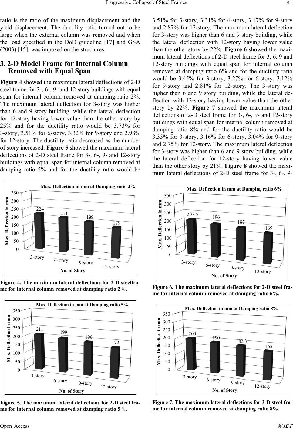
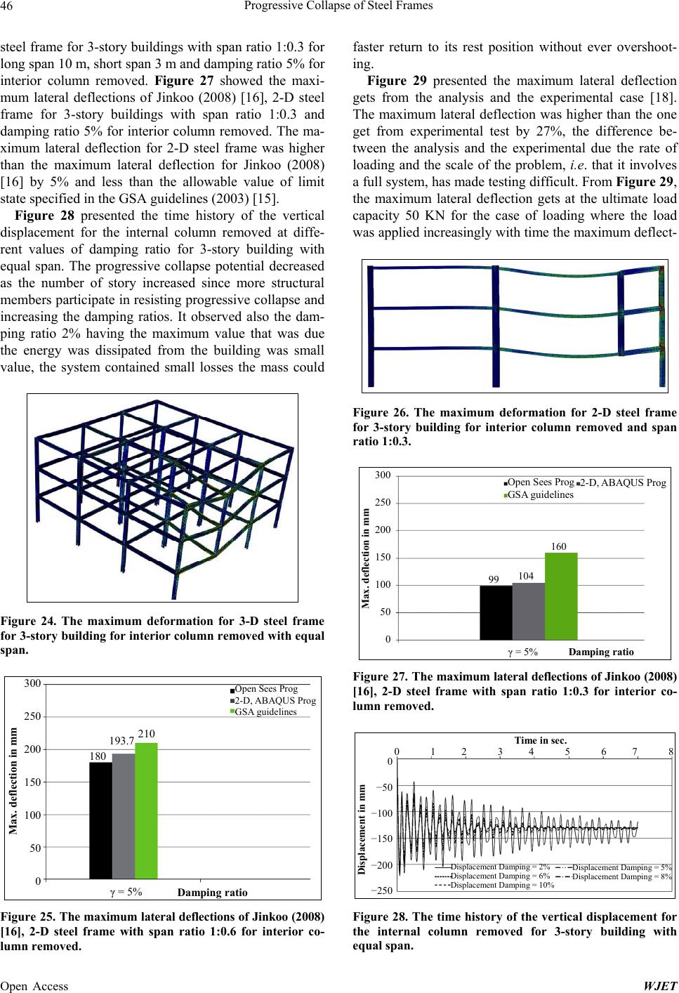
Figure 29. The maximum lateral deflection for internal co-
lumn removed from the analysis and experimental test.
tion would be measured and get around 35 - 36 mm.
7. Conclusions
Nonlinear finite element models investigating the progre-
ssive collapse of steel frames have been developed and
reported in this paper. The finite element models have
accounted for the nonlinear material of the steel frames
and the nonlinear geometry was also considered. The
investigated steel frames had different geometries and
different damping ratios. Overall, the paper addresses
how multistory frames would behave when subjected to
local damage or loss of a main structural carrying
element. The history behavior of the steel frames defor-
mations and failure modes were investigated and
discussed in this paper. The nonlinear finite element
models accented the nonlinear material and geometry
behavior of the steel frames. The study has shown that:
By increasing damping ratios in dynamic analysis the
maximum lateral deflection decreased for all frames.
The progressive collapse potential decreased as the
number of story increased since more structural mem-
bers participate in resisting progressive collapse.
The nonlinear dynamic analysis method provided a
realistic representation of the progressive collapse be-
havior.
The increase only in the girder size for the purpose of
preventing progressive collapse may result in weak
story when the building is subject to seismic load.
The formation of weak story can be prevented by in-
creasing the column size in such a way that the strong
column-weak beam requirement is satisfied.
The maximum lateral deflection obtained for internal
column-removed case using the 3D-model was slightly
higher (within 2%) than that obtained for internal column-
removed case using the 2D-model.
REFERENCES
[1] R. E. Mc Connel and S. J. Kelly, “Structural Aspects of
Progressive Collapse of Warehouse Racking,” The Struc-
tural Engineer, Vol. 61A, No. 11, 1983, pp. 343-347.
[2] F. Casciati and L. Faravelli, “Progressive Failure for
Seismic Reliability Analysis,” Engineering Structures,
Vol. 6, No. 2, 1984, pp. 97-103.
http://dx.doi.org/10.1016/0141-0296(84)90002-6
[3] A. J. Pretlove, “Dynamic Effects in Fail-Safe Structural
Design,” Proceedings, International Conference on Steel
Structures: Recent Advances and their Application to De-
sign, Budva, 1986, pp. 749-757.
[4] J. L. Gross and W. Mcguire, “Progressive Collapse Re-
sistant Design,” Journal of Structural Engineering, Vol.
109, No. 1, 1983, pp. 1-15.
[5] R. M. Bennett, “Formulation for Probability of Progres-
sive Collapse,” Structural Safety, Vol. 5, No. 1, 1988, pp.
67-77. http://dx.doi.org/10.1016/0167-4730(88)90006-9
[6] A. J. Pretlove, M. Ramsden and A. G. Atkins, “Dynamic
Effects in Progressive Failure of Structures,” Interna-
tional Journal of Impact Engineering, Vol. 11, No. 4,
1991, pp. 539-546.
[7] E. M. Smith, “Alternate Path Analysis of Space Trusses
for Progressive Collapse,” Journal of Structural Engi-
neering, Vol. 114, No. 9, 1988, pp. 1978-1999.
http://dx.doi.org/10.1061/(ASCE)0733-9445(1988)114:9(
1978)
[8] R. B. Malla and B. B. Nalluri, “Dynamic Effects of
Member Failure on Response of Truss Type Space Struc-
ture,” Journal of Spacecrafts and Rockets, Vol. 32, No. 3,
1995, pp. 545-551. http://dx.doi.org/10.2514/3.26649
[9] K. Abedi and G. A. R. Parke, “Progressive Collapse of
Single-Layer Braced Domes” International Journal of
Space Structures, Vol. 11, No. 3, 1996, pp. 291-306.
[10] J. R. Gilmour and K. S. Virdi, “Numerical Modeling of
the Progressive Collapse of Framed Structures as a Result
of Impact or Explosion,” 2nd International PhD Sympo-
sium in Civil Engineering, 1998.
[11] G. Kaewkulchai and E. B. Williamson, “Dynamic Be-
havior of Planar Frames during Progressive Collapse”.
16th ASCE Engineering Mechanics Conference, Univer-
sity of Washington, Seattle, 2003.
[12] G. Kaewkulchai and E. B. Williamson, “Beam Element
Formulation and Solution Procedures for Dynamic Pro-
gressive Collapse Analysis,” Computers and Structures,
Vol. 82, No. 7-8, 2004, pp. 639-651.
http://dx.doi.org/10.1016/j.compstruc.2003.12.001
[13] K. Khandelwal and S. El-Tawil, “Collapse Behavior of
Steel Special Moment Resisting Frame Connections,”
Journal of Performance of Constructed Facilities, Vol.
113, No. 5, 2007, pp. 646-665.
[14] J. Kim and J. Park, “Design of Steel Frames Considering
Progressive Collapse,” Steel and Composite Structures,
Vol. 8, No. 1, 2008, pp. 85-98.
http://dx.doi.org/10.12989/scs.2008.8.1.085
[15] GSA, “Progressive Collapse Analysis and Design Guide-
lines for New Federal Office Buildings and Major Mod-
ernization Projects,” The US General Services Admini-
stration, 2003.
Open Access WJET
Progressive Collapse of Steel Frames
Open Access WJET
48
[16] J. Kim and J. Park, “Design of Steel Moment Frames
Considering Progressive Collapse,” Steel and Composite
Structures, Vol. 8, No. 1, 2008, pp. 85-98.
http://dx.doi.org/10.12989/scs.2008.8.1.085
[17] The Unified Facilities Criteria (UFC) 4-023-03, “Design
of Buildings to Resist Progressive Collapse, Approved for
Public Release,” Department of Defense, 2005.
[18] K. S. Kandil, E. A. Ellobody and H. Eldehemy, “Experi-
mental Investigation of Progressive Collapse of a Steel
Frame,” 2013.