 International Journal of Medical Physics, Clinical Engineering and Radiation Oncology, 2013, 2, 139-146 Published Online November 2013 (http://www.scirp.org/journal/ijmpcero) http://dx.doi.org/10.4236/ijmpcero.2013.24019 Open Access IJMPCERO Postmastectomy Scar Boost Irradiation Using HDR Surface Mould Brachytherapy by 3D Image-Based Volume Optimization Neelakandan Vijayaprabhu1, Karunanithi Gunaseelan1*, Nagarajan Vivekanandan2, Nagamuthu Karthik3, Cholayil Shamsudheen1, K. S. Reddy1 1Department of Radiotherapy, Regional Cancer Center, Jawharlal Institute of Postgraduate Medical Education and Research (JIPMER), Puducherry, India 2Department of Medical Physics, Cancer Institute (WIA), Chennai, India 3Department of Medical Physics, Anna University, Chennai, India Email: vijayaprabhu.n@gmail.com, *gunapgi@gmail.com, viveknaren@hotmail.com, carthic0301@gmail.com, shamsu48@gmail.com, atsahara11@yahoo.com Received September 19, 2013; revised October 20, 2013; accepted November 2, 2013 Copyright © 2013 Neelakandan Vijayaprabhu et al. This is an open access article distributed under the Creative Commons Attribu- tion License, which permits unrestricted use, distribution, and reproduction in any medium, provided the original work is properly cited. ABSTRACT Introduction: During postmastectomy radiotherapy (PMRT), it is recommended to boost the postmastectomy surgical scar with additional 10 Gy in 5 fractions in the patients with close or positive surgical margins. The electron beam ther- apy, though cumbersome, is usually preferred since it has the desired rapid fall of a dose beyond R85. An alternative but easier and reproducible treatment method for PMRT surgical scar boost using 3D CT image-based HDR surface mould brachytherapy is introduced and analyses of the target coverage and dose nearby organs-at-risk (OARs) using this method are evaluated in this study. Methods and Materials: This study includes twelve patients (five left-sided and seven right-sided chest wall), who were planned and treated with CT-image based surface mould HDR brachytherapy for chest wall scar boost (CWB) using Catheter Flap SetTM (Varian Medical Systems, USA) that were given concur- rently during external beam radiotherapy (EBRT) treatments. Since no guidelines are available for delineating clinical target volume (CTV) structure to be used for postmastectomy scar boost, the CTV in this study was a uniform 5-mm thick volume drawn at 5 mm beneath the skin (CTVhdr_evl) and its extent was made conforming to the boost area marked on the skin and made visible in CT images by radiopaque wires. Results: Prescribed dose (PD) to CTVhdr_evl is 7.5 Gy in 3 fractions, and 2.5 Gy per fraction. The CTVhdr_evl volume receives the PD with mean V100%, V98% and V95% values which are 98.57%, 99.63% and 100% respectively. The mean dose for heart (MHD) is 2.71 Gy in left-sided CWB and 1.80 Gy in right-sided CWB plans. Mean lung dose (MLD) is 2.48 Gy for ipsilateral lung and 0.76 Gy for contralateral lung. Maximum dose to contralateral breast is 4.93 Gy and the mean dose is 0.79 Gy. The mean percent dose to the skin volume overlying the CTVhdr_evl is 138.6% and 3.7% of skin volume received 200% of the PD. Con- clusion: The 3D image-based HDR surface mould achieved good CTV coverage with acceptable doses to OARs. Pa- tient preparation, treatment planning, and execution in this method are less cumbersome and reproducible. Thus surface mould using flap applicator can be used whenever postmastectomy surgical scar boost is required. Keywords: Postmastectomy Radiation; Surgical Scar Boost; HDR Surface Mould; Catheter Flap 1. Introduction Postmastectomy radiotherapy (PMRT) to chest wall (CW) is recommended in locally advanced breast cancer. In the absence of radiotherapy (RT), loco-regional failure can occur in approximately 25% - 40% of node-positive pa- tients, and in up to 15% - 20% of node-negative patients who do not receive systemic therapy [1]. Even after Da- nish and British Columbia trials, the locoregional risk reduction and impact on survival with PMRT are still de- batable especially in patients with 1 to 3 positive nodes [2-8]. But, it is well established that the surgical scar in the CW is the most frequent site of locoregional recur- *Corresponding author.  N. VIJAYAPRABHU ET AL. Open Access IJMPCERO 140 rence (LRR) [9,10]. Recent studies have suggested that when more than one of the adverse risk factors viz., young age, premeno- pausal status, tumour size, tumour grade, lymphovascular invasion, margin status, nodal ration, estrogen receptor status, tumour subtype, 21-gene recurrence score, and the genomic predictive index are present in the setting of nodal involvement, more aggressive locoregional man- agement is warranted [11,12]. Even as the debate con- tinues, the technological development in External Beam Radiotherapy (EBRT) like Intensity Modulated Radio- therapy (IMRT), Respiratory Gated Radiotherapy, and Volumetric Modulated Radiotherapy (VMAT), and Im- age-Guided Radiotherapy (IGRT), has made it now pos- sible to deliver radiation to Planned Target Volumes (PTV) with minimal setup errors and with acceptable dose coverage, while sparing the organs at risk (OARs). Moreover, efforts are also made to develop atlas-based guidelines for implementing uniformity in delineation of the target and critical structures which are expected to minimize the interpersonal variations [13]. In PMRT, by implementing these technologies and using electrons- photon combinations, it is expected to bring down the pulmonary or cardiac toxicities [14-18]. As the scar in the chest wall is clearly the most com- mon site of loco-regional failure, whenever there is a clo- se or positive margin, and boosting the surgical scar area is considered with a dose of 10 Gy in 5 fractions. Usually enfacing electrons is used to deliver the boost dose. How- ever, planning and preparation for electron treatment are complex, as electron cutouts and dose featherings re- quire time and effort. In this study, an attempt is made to reduce this complexity by introducing HDR surface mould for the chest wall boost (CWB). While boost treat- ment during adjunct radiotherapy following breast con- servation surgery is documented [11], not many data are available about effective methods for CWB during PMRT. A new method for CWB during PMRT using Catheter FlapTM (Varian Medical Systems, USA) surface mold HDR brachytherapy was introduced and its efficacy in dose coverage to tumour volume and sparing the un- derlying critical organs is evaluated. 2. Methods and Materials 2.1. Patient Selection and Materials In this study, the inclusion criteria for surgical scar boost are women who have had mastectomy with positive or close surgical margins; and without cardiac or pulmonary co-morbidities. Twelve patients (five left-sided and seven right-sided chest wall), who had positive or close surgical margins were included prospectively in this study and planned for PMRT with sandwich scar boost using HDR flap surface mould. Commercially available CT/MR co- mpatible flexible Catheter Flap® (Varian Medical Sys- tems, Palo Alto, CA, USA) with 20 channels was used in this study for HDR surface mould treatments (Figure 1). Each channel is separated by 1 cm and this flap is capa- ble of treatments up to 200 mm × 290 mm area. The catheters are slightly radiopaque and thus visible in the CT images. Contouring, segmentation and planning, eva- luations are done by the same radiation oncologist and physicist to minimize interpersonal variations. Optimiza- tion and calculations were performed in BrachyVisionTM (Version 10.0.42) which is integrated in the Eclipse treat- ment planning environment (Varian Medical Systems Inc., Palo Alto, CA, USA). 2.2. Immobilization Methods and Plan Preparation Patients were immobilized with thermoplastic cast made on full carbon fiber breast board in the same supine posi- tion with the ipsilateral arm abducted above head as that required for EBRT for easy image registration. Surface markings were drawn around scar at a distance of 3 cm in the craniocaudal direction and 2 - 3 cm along the medial and lateral borders (Figure 2(a)) by the oncologist. Im- mobilization casts for EBRT were made separately. For CWB, the catheter flap was positioned beneath the cast and on the patient’s chest wall so that the position of catheter flap is fixed in the same position throughout treatments and reproducible during subsequent fractions. Care was taken to keep the patients position same for both EBRT and HDR treatment plans for easy image registrations so that plan sums can be generated later for evaluation. Radioopaque wires were placed on the skin markings and CT scans were taken in the CT-simulator (Siemens Ltd., Germany) with 3 mm slice thickness sep- arately for EBRT and for HDR. Registrations of the im- ages were approved only after matching at least the treatment area (i.e., Chest Wall). Contouring for EBRT was done using RTOG atlas [13]. Before finalizing EBRT plan, HDR Brachytherapy planning was also done Figure 1. Catheter flap setTM (Varian medical systems, USA).  N. VIJAYAPRABHU ET AL. Open Access IJMPCERO 141 (a) (b) (c) (d) (e) Figure 2. Method for CTV delineation: (a) Surface markings made on the patient; (b) Mould is prepared with immobilization and in the same position as in EBRT; (c) 3D view of the surface wire markings; (d) CTVhdr_evl (red) and overlying skin (blue) are delineated using wire images (other OAR structures are hidden); (e) 3D view of the reconstructed CTVhdr_evl (red) conforming to surface markings. with the catheter flap as described below and got evalu- ated for both HDR plan and plan sum with EBRT. 2.3. Method for CTV Delineation The CTV for HDR (CTVhdr_evl) is constructed using ra- dio-opaque wire markers, which were placed along the scar and 3 cm in craniocaudal direction and 2 - 3 cm in lateral extension of the scar as shown in the Figure 2(a). Using the CT images a uniform CTVhdr_evl is con- structed as a 5-mm thick structure lying 5 mm beneath the skin surface (body) using extract wall & cropping tools available in the contouring workspace of the plan-  N. VIJAYAPRABHU ET AL. Open Access IJMPCERO 142 ning system and by using Boolean operators and 3D live view, the boundaries are clipped along the wire markers. (Figures 2(b)-(e)). Five-mm-thick skin volume structure is then created above the CTVhdr_evl structure up to the skin level for giving dose constraints during volume op- timization of the HDR plan. 2.4. Dose Prescription The dose prescription to CTV hdr_evl was 2.5 Gy per fraction given for 3 fractions so that the total dose to be delivered as scar boost is 7.5 Gy for all patients in this study. The EBRT dose prescription was 46 Gy in 23 fractions to entire ipsilateral chest wall and regional nodes with additional two fractions given to supra- clavicular and axillary level 3 nodes. The CTVevl in EBRT is cropped to lie 5 mm from the skin level for better dose coverage in IMRT or VMAT planning. The HDR surface mould dose was limited to 7.5 Gy in 3 fractions which is less than the recommended 10 Gy in 5 fractions by ACR guidelines [11]. This was done because the surface mould usually delivers higher dose to the skin overlying the CTVhdr_evl (D90 ≥ 120%) when compared to dose by enface electrons along with bolus. Thus giving 10 Gy with surface mould may re- sult in higher skin reactions. The three HDR fractions are interdigitated with EBRT treatments and scheduled to be delivered after completion of every 5 fractions of EBRT, with no EBRT delivered on the days of HDR treatments. 2.5. Catheter Reconstruction and Source Dwell Positionings The catheter auto-construction tool in the BrachyVi sionTM is used to reconstruct the catheters. Once the ca- theters are constructed, using the source dwell positions placement tool, sources with 5 mm step sizes were made to dwell only above this CTVhdr_evl area with two or three additional dwell positions beyond its boundary (Fig- ure 2(d)). These procedures are completed usually in 20 to 30 minutes. 2.6. Inverse Planning Optimization In this study treatment planning was done using inverse planning Adaptive Volume Optimization (AVOL) al- gorithm available in the BrachyVisionTM Version 10.0.42. This optimization algorithm attempts to achieve the specified objectives and constraints with smoother dwell times and fewer hot spots inside the structures. The system default minimum and maximum dose limits to target are 95% and 120% with 100% priority for both, which were modified during later iterations so that V100% ≥ 98% is achieved. If dose to skin exceeds beyond 200%, then the penalty score to skin constraint is set higher in subsequent iterations. As the planning optimization is interactive, normally two or three itera- tions are enough to achieve the desired dose distribu- tion. But in a few patients studied here, after perform- ing optimization, isodose reshaper tool was used to improve the dose distribution by dragging the isodose lines using mouse in selected CT slices to achieve re- quired dose values in them. Suitable plans for evalua- tion are the ones whose V100% is at least 95%. Dose dis- tributions are evaluated slice by slice qualitatively and then quantitatively by using dose volume histograms (DVHs). 3. Results Various volume and dosimetric parameters that show the coverage of CTVhdr_evl are listed in Table 1. The sta- tistical descriptive analysis (95% CI of mean & Quartile deviation) were done using GraphPad Prism 6 (v6.02) for Windows. V80% and V90% were chosen as these parame- ters indicate minimum dose received by the CTV. The parameters V95% and V98% show that there is a good cov- erage of dose to CTV (mean = 99.8%, SD = 0.47, n = 12; and mean = 99.47%, SD = 0.93, n = 12; respectively) and that the level of homogeneity of dose inside the CTV. V100% (%) indicates the proportion of CTV receiving at least the prescribed dose, and it is seen that 98.57% of the CTV volume receives 100% prescribed dose. To show the level of maximum dose inside the CTV, V150% is chosen, as it is used routinely in reporting brachyther- apy treatments, whose values (mean = 2.58%, SD = 2.38, n = 12) in this study are acceptable. Table 2 lists the dose-volume parameters for the heart. For the left-sided chest wall patients, the Dmean, and Dmedian values are 36% and 33% of the prescribed dose respec- tively. The maximum dose to heart is around 71% of the prescribed dose. For the right-sided chest wall patients, the corresponding values are 24%, 23%, and 50% re- spectively. As for the other OARs, as given in Table 3, the dose- volume parameters were chosen as relevant to total dose of 7.5 Gy prescribed in this study. Thus, the volume pa- rameter for lungs is limited to V5Gy, apart from giving mean and maximum doses. For contralateral breast, V5% and V10% were given, which will be required if EBRT for the chest wall was delivered using IMRT or VMAT techniques, which invariably delivers low doses to this contralateral breast. Thus, the total value for V5% and V10%, from plan sum of both EBRT and HDR, will give the input for calculating secondary cancer incidence pro- bability. Table 3 also lists the dose delivered to the skin. The parameters used are V150% and V200%, as they give the level of high doses given to skin volumes. They also can be used to predict and to explain various skin reactions  N. VIJAYAPRABHU ET AL. Open Access IJMPCERO 143 Table 1. CTV dose-volume parameters. CTV metrics Mean (SD) n = 12 Range 95% CI of mean CTVhdr_evl volume: 78.79 (21.11) cm3 Volume Parameters V80% (%) 100 (0.0) 100 - 100 100 - 100 V90% (%) 99.95 (0.14) 99.5 - 100 99.86 - 100 V95% (%) 99.8 (0.47) 98.33 - 100 99.80 - 100.1 V98% (%) 99.47 (0.93) 96.61 - 100 98.88 - 100.1 V100% (%) 98.57 (1.44) 94.49 - 99.95 97.66 - 99.49 V150% (%) 2.58 (2.38) 0.29 - 7.88 1.066 - 4.09 Dose Parameters D90% (%) 103.5 (1.06) 101.9 - 106.1 102.8 - 104.2 D98% (%) 100.7 (1.79) 95.82 - 102.9 99.54 - 101.8 Abbreviations: SD = standard deviation; Vx% (%) = percent volume receiving at least x% of the prescribed dose; Dy% (%) = percent dose received by the y% of the volume. Table 2. Dose volume parameters for heart. Left side chest wall (n = 5) Right side chest wall (n = 7) Metric Mean (SD) Range 95% CI of Mean Mean (SD) Range 95% CI of Mean Heart Volume in cc 396 (116.6) 419.5 (105.1) Dmean (cGy) 271.6 (42.87) 231 - 335.7 218.4 - 324.8 180.1 (27.13) 149.2 - 220.6 155 - 205.2 Dmedia n (cGy) 248.2 (45.23) 203.9 - 21.5 192.1 - 304.4 172.7 (30.55) 133.4 - 216.7 144.4 - 200.9 Dmax (c Gy ) 532.5 (88.22) 420.5 - 658.8 422.9 - 642 374 (48.13) 313.4 - 447.5 329.5 - 418.5 V5Gy (%) 4.886 (4.562) 0 - 10.28 −0.78 - 10.55 0 Abbreviations: SD = standard deviation; CI = confidence interval; D2% (cGy) = Dose received by 2% of the volume; V5Gy (%) = percent volume receiving at least 5 Gy dose. Table 3. Dose volume parameters for OARs. Both right & left side chest wall (n = 12) Metrics Mean (SD) Range 95% CI of Mean Ipsilateral Lung Volume in cm3 876.6 (294.2) DMean (cGy) 248.2 (28.23) 201.4 - 282.3 230.3 - 266.2 DMax (cGy) 711.6 (105.8) 438.4 - 846.6 644.4 - 778.9 D2% (cGy) 602.2 (54.69) 491.5 - 692.1 567.5 - 637 V5Gy (%) 3.606 (4.327) 0 - 12.63 0.86 - 6.35 Contralateral Lung Volume in cm3 802.9 (188.2) DMean (cGy) 76.13 (15.58) 59.2 - 113.8 66.23 - 86.03 DMax (cGy) 305.6 (126.9) 148.2 - 557.4 224.9 - 386.2 V5Gy (%) 0 (0) 0 - 0 Contralateral Breast Volume in cm3 662.1 (263.1) DMean (cGy) 79.28 (14.02) 55.2 - 102.5 70.38 - 88.19 DMax (cGy) 492.7 (166.2) 273.9 - 765.4 387.1 - 598.2 V5Gy (%) 0.27 (0) 0.27 - 0.27 V5% (%) 89.22 (11.44) 62.45 - 100 81.95 - 96.48 V10% (%) 34.69 (9.659) 17.49 - 53.1 28.55 - 40.82 Skin Volume in cm3 78.43 (22.67) DMean (%) 138.6 (3.183) 131.7 - 143.8 136.5 - 140.6 V150% (%) 18.85 (3.897) 10.93 - 25.7 16.38 - 21.33 V200% (%) 3.686 (1.765) 1 - 7.49 2.565 - 4.807 Abbreviations: SD = standard deviation; CI = confidence interval; DMean, DMax = Mean, Maximum doses; D2% (cGy) = Dose received by 2% of the volume; V5Gy (%) = percent volume receiving at least 5Gy dose; Vx% (%) = percent volume receiving at least x% of the dose. 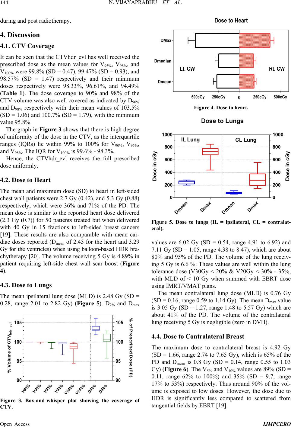 N. VIJAYAPRABHU ET AL. Open Access IJMPCERO 144 during and post radiotherapy. 4. Discussion 4.1. CTV Coverage It can be seen that the CTVhdr_evl has well received the prescribed dose as the mean values for V95%, V98%, and V100% were 99.8% (SD = 0.47), 99.47% (SD = 0.93), and 98.57% (SD = 1.47) respectively and their minimum doses respectively were 98.33%, 96.61%, and 94.49% (Table 1). The dose coverage to 90% and 98% of the CTV volume was also well covered as indicated by D90% and D98% respectively with their mean values of 103.5% (SD = 1.06) and 100.7% (SD = 1.79), with the minimum value 95.8%. The graph in Figure 3 shows that there is high degree of uniformity of the dose in the CTV, as the interquartile ranges (IQRs) lie within 99% to 100% for V90%, V95%, and V98%. The IQR for V100% is 99.6% - 98.3%. Hence, the CTVhdr_evl receives the full prescribed dose uniformly. 4.2. Dose to Heart The mean and maximum dose (SD) to heart in left-sided chest wall patients were 2.7 Gy (0.42), and 5.3 Gy (0.88) respectively, which were 36% and 71% of the PD. The mean dose is similar to the reported heart dose delivered (2.3 Gy (0.7)) for 50 patients treated but when delivered with 40 Gy in 15 fractions to left-sided breast cancers [19]. These results are also comparable with mean car- diac doses reported (Dmean of 2.45 for the heart and 3.29 Gy for the ventricles) when using balloon-based HDR bra- chytherapy [20]. The volume receiving 5 Gy is 4.89% in patient requiring left-side chest wall scar boost (Figure 4). 4.3. Dose to Lungs The mean ipsilateral lung dose (MLD) is 2.48 Gy (SD = 0.28, range 2.01 to 2.82 Gy) (Figure 5). D2% and Dmax Figure 3. Box-and-whisper plot showing the coverage of CTV. Figure 4. Dose to heart. Figure 5. Dose to lungs (IL = ipsilateral, CL = contralat- eral). values are 6.02 Gy (SD = 0.54, range 4.91 to 6.92) and 7.11 Gy (SD = 1.05, range 4.38 to 8.47), which are about 80% and 95% of the PD. The volume of the lung receiv- ing 5 Gy is 6.6 %. These values are well within the lung tolerance dose (V30Gy < 20% & V20Gy < 30% - 35%, with MLD of < 10 Gy when summed with EBRT dose using IMRT/VMAT plans. The mean contralateral lung dose (MLD) is 0.76 Gy (SD = 0.16, range 0.59 to 1.14 Gy). The mean Dmax value is 3.05 Gy (SD = 1.27, range 1.48 to 5.57 Gy) which are about 41% of the PD. The volume of the contralateral lung receiving 5 Gy is negligible (zero in DVH). 4.4. Dose to Contralateral Breast The maximum dose to contralateral breast is 4.92 Gy (SD = 1.66, range 2.74 to 7.65 Gy), which is 65% of the PD and Dmean is 0.8 Gy (SD = 0.14, range 0.55 to 1.03 Gy) (Figure 6). The V5% and V10% values are 89% (SD = 0.11, range 62% to 100%) and 35% (SD = 9.7, range 17% to 53%) respectively. Thus around 90% of the vol- ume is exposed to low doses. However, the dose due to HDR is significantly less compared to scattered from tangential fields by EBRT [19]. 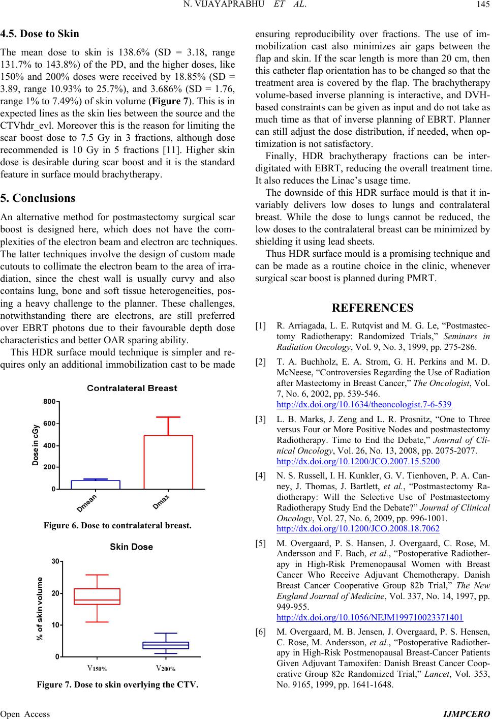 N. VIJAYAPRABHU ET AL. Open Access IJMPCERO 145 4.5. Dose to Skin The mean dose to skin is 138.6% (SD = 3.18, range 131.7% to 143.8%) of the PD, and the higher doses, like 150% and 200% doses were received by 18.85% (SD = 3.89, range 10.93% to 25.7%), and 3.686% (SD = 1.76, range 1% to 7.49%) of skin volume (Figure 7). This is in expected lines as the skin lies between the source and the CTVhdr_evl. Moreover this is the reason for limiting the scar boost dose to 7.5 Gy in 3 fractions, although dose recommended is 10 Gy in 5 fractions [11]. Higher skin dose is desirable during scar boost and it is the standard feature in surface mould brachytherapy. 5. Conclusions An alternative method for postmastectomy surgical scar boost is designed here, which does not have the com- plexities of the electron beam and electron arc techniques. The latter techniques involve the design of custom made cutouts to collimate the electron beam to the area of irra- diation, since the chest wall is usually curvy and also contains lung, bone and soft tissue heterogeneities, pos- ing a heavy challenge to the planner. These challenges, notwithstanding there are electrons, are still preferred over EBRT photons due to their favourable depth dose characteristics and better OAR sparing ability. This HDR surface mould technique is simpler and re- quires only an additional immobilization cast to be made Figure 6. Dose to contralateral breast. Figure 7. Dose to skin overlying the CTV. ensuring reproducibility over fractions. The use of im- mobilization cast also minimizes air gaps between the flap and skin. If the scar length is more than 20 cm, then this catheter flap orientation has to be changed so that the treatment area is covered by the flap. The brachytherapy volume-based inverse planning is interactive, and DVH- based constraints can be given as input and do not take as much time as that of inverse planning of EBRT. Planner can still adjust the dose distribution, if needed, when op- timization is not satisfactory. Finally, HDR brachytherapy fractions can be inter- digitated with EBRT, reducing the overall treatment time. It also reduces the Linac’s usage time. The downside of this HDR surface mould is that it in- variably delivers low doses to lungs and contralateral breast. While the dose to lungs cannot be reduced, the low doses to the contralateral breast can be minimized by shielding it using lead sheets. Thus HDR surface mould is a promising technique and can be made as a routine choice in the clinic, whenever surgical scar boost is planned during PMRT. REFERENCES [1] R. Arriagada, L. E. Rutqvist and M. G. Le, “Postmastec- tomy Radiotherapy: Randomized Trials,” Seminars in Radiation Oncology, Vol. 9, No. 3, 1999, pp. 275-286. [2] T. A. Buchholz, E. A. Strom, G. H. Perkins and M. D. McNeese, “Controversies Regarding the Use of Radiation after Mastectomy in Breast Cancer,” The Oncologist, Vol. 7, No. 6, 2002, pp. 539-546. 0http://dx.doi.org/10.1634/theoncologist.7-6-539 [3] L. B. Marks, J. Zeng and L. R. Prosnitz, “One to Three versus Four or More Positive Nodes and postmastectomy Radiotherapy. Time to End the Debate,” Journal of Cli- nical Oncology, Vol. 26, No. 13, 2008, pp. 2075-2077. 1http://dx.doi.org/10.1200/JCO.2007.15.5200 [4] N. S. Russell, I. H. Kunkler, G. V. Tienhoven, P. A. Can- ney, J. Thomas, J. Bartlett, et al., “Postmastectomy Ra- diotherapy: Will the Selective Use of Postmastectomy Radiotherapy Study End the Debate?” Journal of Clinical Oncology, Vol. 27, No. 6, 2009, pp. 996-1001. 2http://dx.doi.org/10.1200/JCO.2008.18.7062 [5] M. Overgaard, P. S. Hansen, J. Overgaard, C. Rose, M. Andersson and F. Bach, et al., “Postoperative Radiother- apy in High-Risk Premenopausal Women with Breast Cancer Who Receive Adjuvant Chemotherapy. Danish Breast Cancer Cooperative Group 82b Trial,” The New England Journal of Medicine, Vol. 337, No. 14, 1997, pp. 949-955. 3http://dx.doi.org/10.1056/NEJM199710023371401 [6] M. Overgaard, M. B. Jensen, J. Overgaard, P. S. Hensen, C. Rose, M. Andersson, et al., “Postoperative Radiother- apy in High-Risk Postmenopausal Breast-Cancer Patients Given Adjuvant Tamoxifen: Danish Breast Cancer Coop- erative Group 82c Randomized Trial,” Lancet, Vol. 353, No. 9165, 1999, pp. 1641-1648. 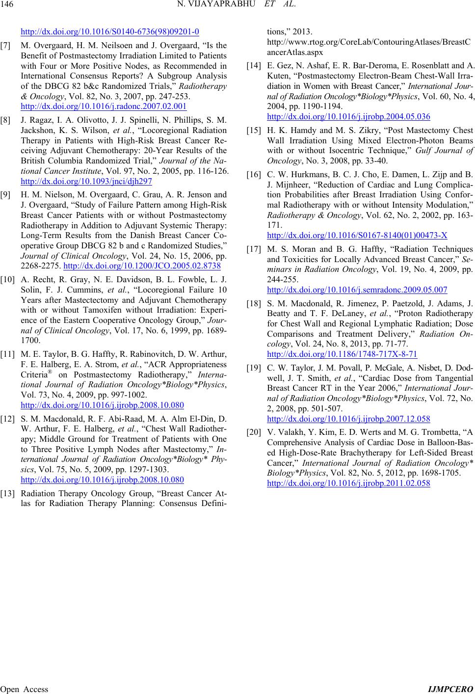 N. VIJAYAPRABHU ET AL. Open Access IJMPCERO 146 4http://dx.doi.org/10.1016/S0140-6736(98)09201-0 [7] M. Overgaard, H. M. Neilsoen and J. Overgaard, “Is the Benefit of Postmastectomy Irradiation Limited to Patients with Four or More Positive Nodes, as Recommended in International Consensus Reports? A Subgroup Analysis of the DBCG 82 b&c Randomized Trials,” Radiotherapy & Oncology, Vol. 82, No. 3, 2007, pp. 247-253. 5http://dx.doi.org/10.1016/j.radonc.2007.02.001 [8] J. Ragaz, I. A. Olivotto, J. J. Spinelli, N. Phillips, S. M. Jackshon, K. S. Wilson, et al., “Locoregional Radiation Therapy in Patients with High-Risk Breast Cancer Re- ceiving Adjuvant Chemotherapy: 20-Year Results of the British Columbia Randomized Trial,” Journal of the Na- tional Cancer Institute, Vol. 97, No. 2, 2005, pp. 116-126. 6http://dx.doi.org/10.1093/jnci/djh297 [9] H. M. Nielson, M. Overgaard, C. Grau, A. R. Jenson and J. Overgaard, “Study of Failure Pattern among High-Risk Breast Cancer Patients with or without Postmastectomy Radiotherapy in Addition to Adjuvant Systemic Therapy: Long-Term Results from the Danish Breast Cancer Co- operative Group DBCG 82 b and c Randomized Studies,” Journal of Clinical Oncology, Vol. 24, No. 15, 2006, pp. 2268-2275. 7http://dx.doi.org/10.1200/JCO.2005.02.8738 [10] A. Recht, R. Gray, N. E. Davidson, B. L. Fowble, L. J. Solin, F. J. Cummins, et al., “Locoregional Failure 10 Years after Mastectectomy and Adjuvant Chemotherapy with or without Tamoxifen without Irradiation: Experi- ence of the Eastern Cooperative Oncology Group,” Jour- nal of Clinical Oncology, Vol. 17, No. 6, 1999, pp. 1689- 1700. [11] M. E. Taylor, B. G. Haffty, R. Rabinovitch, D. W. Arthur, F. E. Halberg, E. A. Strom, et al., “ACR Appropriateness Criteria® on Postmastectomy Radiotherapy,” Interna- tional Journal of Radiation Oncology*Biology*Physics, Vol. 73, No. 4, 2009, pp. 997-1002. 8http://dx.doi.org/10.1016/j.ijrobp.2008.10.080 [12] S. M. Macdonald, R. F. Abi-Raad, M. A. Alm El-Din, D. W. Arthur, F. E. Halberg, et al., “Chest Wall Radiother- apy; Middle Ground for Treatment of Patients with One to Three Positive Lymph Nodes after Mastectomy,” In- ternational Journal of Radiation Oncology*Biology* Phy- sics, Vol. 75, No. 5, 2009, pp. 1297-1303. 9http://dx.doi.org/10.1016/j.ijrobp.2008.10.080 [13] Radiation Therapy Oncology Group, “Breast Cancer At- las for Radiation Therapy Planning: Consensus Defini- tions,” 2013. http://www.rtog.org/CoreLab/ContouringAtlases/BreastC ancerAtlas.aspx [14] E. Gez, N. Ashaf, E. R. Bar-Deroma, E. Rosenblatt and A. Kuten, “Postmastectomy Electron-Beam Chest-Wall Irra- diation in Women with Breast Cancer,” International Jour- nal of Radiation Oncology*Biology*Physics, Vol. 60, No. 4, 2004, pp. 1190-1194. 1http://dx.doi.org/10.1016/j.ijrobp.2004.05.036 [15] H. K. Hamdy and M. S. Zikry, “Post Mastectomy Chest Wall Irradiation Using Mixed Electron-Photon Beams with or without Isocentric Technique,” Gulf Journal of Oncology, No. 3, 2008, pp. 33-40. [16] C. W. Hurkmans, B. C. J. Cho, E. Damen, L. Zijp and B. J. Mijnheer, “Reduction of Cardiac and Lung Complica- tion Probabilities after Breast Irradiation Using Confor- mal Radiotherapy with or without Intensity Modulation,” Radiotherapy & Oncology, Vol. 62, No. 2, 2002, pp. 163- 171. 1http://dx.doi.org/10.1016/S0167-8140(01)00473-X [17] M. S. Moran and B. G. Haffty, “Radiation Techniques and Toxicities for Locally Advanced Breast Cancer,” Se- minars in Radiation Oncology, Vol. 19, No. 4, 2009, pp. 244-255. 1http://dx.doi.org/10.1016/j.semradonc.2009.05.007 [18] S. M. Macdonald, R. Jimenez, P. Paetzold, J. Adams, J. Beatty and T. F. DeLaney, et al., “Proton Radiotherapy for Chest Wall and Regional Lymphatic Radiation; Dose Comparisons and Treatment Delivery,” Radiation On- cology, Vol. 24, No. 8, 2013, pp. 71-77. 1http://dx.doi.org/10.1186/1748-717X-8-71 [19] C. W. Taylor, J. M. Povall, P. McGale, A. Nisbet, D. Dod- well, J. T. Smith, et al., “Cardiac Dose from Tangential Breast Cancer RT in the Year 2006,” International Jour- nal of Radiation Oncology*Biology*Physics, Vol. 72, No. 2, 2008, pp. 501-507. 1http://dx.doi.org/10.1016/j.ijrobp.2007.12.058 [20] V. Valakh, Y. Kim, E. D. Werts and M. G. Trombetta, “A Comprehensive Analysis of Cardiac Dose in Balloon-Bas- ed High-Dose-Rate Brachytherapy for Left-Sided Breast Cancer,” International Journal of Radiation Oncology* Biology*Physics, Vol. 82, No. 5, 2012, pp. 1698-1705. 1http://dx.doi.org/10.1016/j.ijrobp.2011.02.058
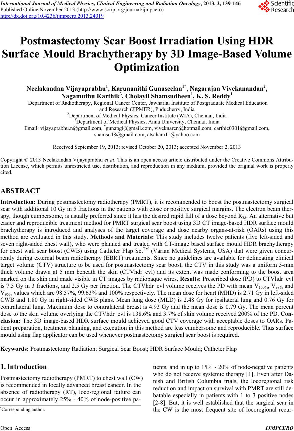
|