Energy and Power Engineering, 2013, 5, 636-641
doi:10.4236/epe.2013.54B123 Published Online July 2013 (http://www.scirp.org/journal/epe)
Research of Mining STATCOM Based on Hybrid
Multilevel H-bridge Inverter*
Yaopu Li, Cong Wang, Xu Zhao, Kai Zhang
China University of Mining & Technology (Beijing), Beijing, China
Email: li.yaopu@hotmail.com
Received January, 2013
ABSTRACT
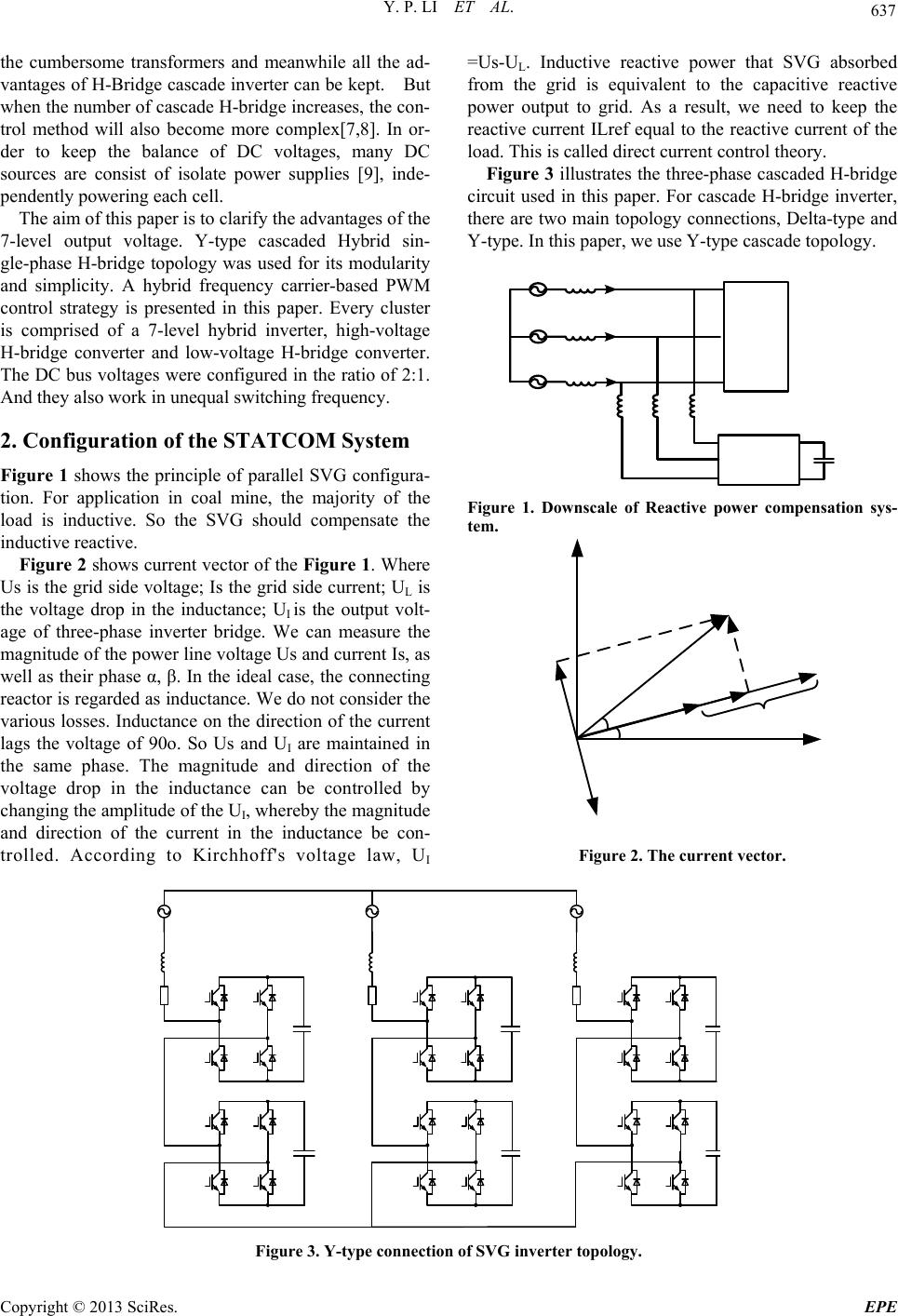
The paper presents a new STATCOM system based on H-bridge inverter. It can be used in mine power network. It has
been commonly verified for the positive effects of SVG on the reactive power compensation and voltage fluctuation
suppression. This paper focuses on a generalized structure of multilevel power converter where individual voltage
sources are not necessarily the same. The cascade H-bridge consists of two cells, high-voltage cell and low-voltage cell.
The high-voltage cell is responsible for voltage lifting, while the low-voltage cell is responsible for PWM modulation.
If two cells are cascaded with DC voltages in a ratio of 2:1, the single-phase output voltage can reach 7 levels. Increas-
ing voltage levels of output waveform can bring up AC current quality, optimize harmonic spectrum and enhance con-
verter efficiency. The hybrid multilevel is characterized by per-phase series connection of a high-voltage H-bridge con-
verter and a low-voltage H-bridge converter. Due to the different capacitor voltage, it is a key problem as to how to
maintain the capacitor’s voltage at a reference level. Independent DC source can effectively ensure the DC voltage.
Through the reactive power compensation technology, the three-phase voltage and current can remain at the same
phase.
Keywords: H-bridge; STATCOM; SVG; Hybrid; Coal Mine; PWM Control; Inverter
1. Introduction
Early reactive power compensation is mainly for passive
device, which is using a certain capacity of the capacitor
or reactor. It is directly connected in parallel or series in
a circuit. This kind of device is operated by mechanical
switch cut. So the application is mainly used for me-
chanical cast cut capacitor (MSC). But it has no rapidity,
continuity, repeatability characteristics. However, when
the SVG come to the application, it can continuous con-
trol the impedance of the device and adjust for inductor
or capacitor.
With the rapid development of modern coal mine, the
use of high power motor brings up a lot of reactive power.
This kind of situation is very outstanding in the mining
coal face. It becomes obvious especially on-peak demand.
Therefore, the dynamic reactive power compensation
technology research is of important significance in coal
mine underground. It is ensuring the production, saving
energy and reducing consumption.
Multilevel power conversion has drawn heavy atten-
tion in the area of medium-voltage industrial applications
and high-power applications [1-3]. In [3], the
high-voltage H-bridge used IGCT instead of IGBT. It has
been proven that the voltage blocking capability of faster
devices, such as IGBT, and the switching speed of high
voltage thyristor-based devices, such as IGCT, is limited.
So the combination of the two types of thyristors can
bring each own advantages to the circuit.
When the DC voltages have various ratios, the number
of output levels is also different. An extension of con-
ventional multilevel topology with the series connection
of unequal DC voltage sources is adopted in literature [4]
[5]. The topology effectively output a higher voltage lev-
els compared with traditional H-bridge converter. Lit-
erature [5] provides a motor drive direct torque control
(DTC) scheme for electric vehicles (EVs) or hybrid EVs.
The limitation is that the control method is not applicable
to STATCOM in which capacitors are replaced in de-
pendent DC power.
Compared with conventional STATCOM, some paper
proposed a new topology from hybrid cascading one
NPC inverter and several conventional H-Bridge invert-
ers. A control method is also proposed to realize DC
voltage regulation of series-connected multiple cells in
the STATCOM operation, making it possible to remove
DC sources from all H-bridge cells [6]. It will eliminate
*The Fundamental Research Funds for the Central Universities. (2010-
YJ03) Supported byNational Natural Science Foundation of China.
(51077125).
Copyright © 2013 SciRes. EPE
Y. P. LI ET AL. 637
the cumbersome transformers and meanwhile all the ad-
vantages of H-Bridge cascade inverter can be kept. But
when the number of cascade H-bridge increases, the con-
trol method will also become more complex[7,8]. In or-
der to keep the balance of DC voltages, many DC
sources are consist of isolate power supplies [9], inde-
pendently powering each cell.
The aim of this paper is to clarify the advantages of the
7-level output voltage. Y-type cascaded Hybrid sin-
gle-phase H-bridge topology was used for its modularity
and simplicity. A hybrid frequency carrier-based PWM
control strategy is presented in this paper. Every cluster
is comprised of a 7-level hybrid inverter, high-voltage
H-bridge converter and low-voltage H-bridge converter.
The DC bus voltages were configured in the ratio of 2:1.
And they also work in unequal switching frequency.
2. Configuration of the STATCOM System
Figure 1 shows the principle of parallel SVG configura-
tion. For application in coal mine, the majority of the
load is inductive. So the SVG should compensate the
inductive reactive.
Figure 2 shows current vector of the Figure 1. Where
Us is the grid side voltage; Is the grid side current; UL is
the voltage drop in the inductance; UI is the output volt-
age of three-phase inverter bridge. We can measure the
magnitude of the power line voltage Us and current Is, as
well as their phase α, β. In the ideal case, the connecting
reactor is regarded as inductance. We do not consider the
various losses. Inductance on the direction of the current
lags the voltage of 90o. So Us and UI are maintained in
the same phase. The magnitude and direction of the
voltage drop in the inductance can be controlled by
changing the amplitude of the UI, whereby the magnitude
and direction of the current in the inductance be con-
trolled. According to Kirchhoff's voltage law, UI
=Us-UL. Inductive reactive power that SVG absorbed
from the grid is equivalent to the capacitive reactive
power output to grid. As a result, we need to keep the
reactive current ILref equal to the reactive current of the
load. This is called direct current control theory.
Figure 3 illustrates the three-phase cascaded H-bridge
circuit used in this paper. For cascade H-bridge inverter,
there are two main topology connections, Delta-type and
Y-type. In this paper, we use Y-type cascade topology.
Figure 1. Downscale of Reactive power compensation sys-
tem.
Figure 2. The current vector.
Figure 3. Y-type connection of SVG inverter topology.
Copyright © 2013 SciRes. EPE
Y. P. LI ET AL.
638
3. Control Strategy of SVG
3.1. Modulation Strategy of SVG Converter
The three-phase inverter is composed of three Clusters.
Each cluster of the hybrid multilevel inverter combines a
high-voltage converter cell 1 with 200 V DC-link, and a
low-voltage converter cell 2 with 100 V DC-link. Switch-
ing frequencies of 50 Hz and 1 kHz are assigned to high-
voltage converter and low-voltage converter in this ex-
periment.
The high-voltage bridge arm is responsible for voltage
lifting, while the low-voltage bridge arm is responsible
for PWM rectifier. Seven-level output voltages are -300,
-200, -100, 0, 100, 200 and 300, respectively shown in
Figures 4 and 5. For example, when the desired output is
between 0 and 100, the high-voltage bridge should output
0 and the low-voltage bridge output 0 to 100. When the
desired output is between 100 and 200, the high-voltage
bridge should output 200 whereas the low-voltage bridge
output 0 to -100. Through this PWM control strategy, the
two-stage voltage stack can output seven levels. Control
strategies of each cell are individually shown in Table 1.
Figure 4. Square wavefor m of Cell1 and PWM wave for m of Cell 2.
Figure 5. Hybr id sever-level PWM modulation sc he me.
Copyright © 2013 SciRes. EPE
Y. P. LI ET AL. 639
.2. Instantaneous Reactive P
vol-
3ower Detection
Assume that ea, eb, ec and ia, ib, ic are the three-phase
tage and current values of the circuit. To facilitate analy-
sis, the voltage current instantaneous value of the
three-phase static coordinate system a-b-c can be trans-
formed into two-phase static coordinate system α-
β.This is called Clarke transformation.
32
1
1
e
 1
222
333
022
aa
bb
c
c
e
eCe e
ee
e

  


 

 
 

(1)
32
11
1
222
333
022
a
bb
cc
ii
iCi i
iii

 


  


  

  
 


a
(2)
The instantaneous active current and instantaneous re-
active current of the system can be calculated through
Park transformation. This current is expressed as:
22
p
q
ee
ii i
ee
C
ii i
ee
ee




  


  

 
 


11
1
sin cos
cos sin
tt
t
1
i
i
t









(3)
As is shown in Figure 6, the three-phase grid voltage
an
he grid. The output of the PI
4. Simulation of the Hybrid Multilevel
Ind hybrid cascaded in-
ure 7 illustrates the phase difference between the
Desired output Low-voltage
d current are assumed as Ua, Ub, Uc and Ia, Ib and Ic. Ial,
Ibl and Icl are the three-phase current of the inductance.
After 3-2 Clarke and Park transformation of current, we
can get the inductance reactive current Iql and grid reac-
tive current Iq. Compare the reactive current of the in-
ductance with the reactive current of the grid, then put
the subtraction Id* into PI regulator. In this way, the re-
active current of the grid can be tracked and compensated.
The circuit is regarded as an ideal model that does not
deliver active power to t
regulator is the three-phase input voltage of the cascade
inverter, which are Uaref , Ubref and Ucref.
H-bridge STATCOM
order to validate the propose
verter structure and the control algorithm, a hybrid seven
level cascade inverter simulation has been built in Simu-
link.
Fig
Table 1. Control stategy.
voltage
High-voltege
converter converter
0100 0 0100
1 2
-
0020000 0-100
200300 200 0100
0-100 0
-
0-100
100-200 2000100
-200-300 -200 0-100
Figure 6. The strategy of reactive power detection.
Figure 7. Phase comparison of voltage and current after compensation.
Copyright © 2013 SciRes. EPE
Y. P. LI ET AL.
640
00.01 0.020.03 0.040.05 0.060.07 0.080.09 0.1
-5
0
5
Sel ect ed si gnal : 5 cycles. FFT window (in red): 2 cycles
Time
(
s
)
0 2 46 810 12 14 161820
0
20
40
60
80
100
Harmoni c order
F
un
d
amen
t
a
l
(50H
z
)
=
3
.
918
,
THD
=
1
.
81%
Mag (% of F undamental)
Figure 8. FFT analysis of compensation current IL.
Figure 9. The tracking waveform of active and reactive current.
oltage and cureent of the three-phase grid after the
alysis of the compensation
cu
king situation of the active and reactive current is
sh
t DC-level of hybrid cascaded multi-
level transform circuit, this paper proposed a new PWM
dual phase control, it is faster to
of
COM. With the right control strategy to
di
v
compensasion when t = 0.04 s. Before compensation, as
the connecting reactor is regarded as inductance in the
ideal case, the voltage phase is therefore ahead of the
current phase by 90o. When the reactive power compen-
sation is integrated in the system, the two waveforms
maintain in the same phase.
Figure 8 shows the FFT an
rrent. The THD = 1.81% with a better harmonic spec-
trum.
Trac
own as in Figure 9.
5. Conclusions
Based on the inpu
control method. The two cascaded H-bridge have differ-
ent DC voltages. The Matlab simulation results have
shown that by stacking the output current, the proposed
operation strategy is feasible. It effectively improves the
system output voltage level and simultaneously reduces
the harmonic content.
Due to the fact that cascade control of multilevel in-
verter is based on indivi
fset current reaction speed by direct current control of
the converter.
This paper studies a kind of applied DC power hybrid
cascade STAT
rectly control the voltage of the capacitance, cost will
be lower and operation more practical. This will greatly
promote the application of reactive power compensation.
Copyright © 2013 SciRes. EPE
Y. P. LI ET AL. 641
REFERENCES
[1] M. D. Manjrekar and T. A. LipoA, “Hybrid Multilevel
Inverter Topology for Drive Applications,” Conference
Proceedings -lectronics Confer-
ence and Expo98, pp. 523-529.
, No. 2, 2005, pp. 655-664.
IEEE Applied Power E
sition - APEC, Vol. 2, 19
[2] M. D. Manjrekar, Peter-steimer and T. A. Lipo, “Hybrid
Multilevel Power Conversion System: a competitive solu-
tion for high power applications,” Conference Record of
the 1999 IEEE Industry Applications Conference.
Thirty-Forth IAS Annual Meeting (Cat. No.99CH36370),
Vol. 3, 1999, pp. 1520-1527.
[3] M. Veenstra and A. Rufer, “Control of a Hybrid Asym-
metric Multilevel Inverter for Competitive Me-
dium-Voltage Industrial Drives,” IEEE Transactions on
Industry Applications, Vol. 41
doi:10.1109/TIA.2005.844382
[4] M. D. Manjrekar and T. A. Lip0A, “Generalized Struc-
ture of Multilevel Power Converter,” 1998 International
Conference on Power Electronics Drives and Energy
Systems for Industrial Growth (IEEE Cat. No.98TH8362),
Vol. 1, 1998, pp. 62-67.
[5] F. Khoucha, S. M. Lagoun, K. Marouani, A. Kheloui and
M. E. H. Benbouzid, “Hybrid Cascaded H-Bridge Multi-
level-Inverter Induction-Motor-Drive Direct Torque Con-
trol for Automotive Applications,” IEEE Transactions on
Industrial Electronics, Vol. 57, No. 3, 2010, pp. 892-899.
doi:10.1109/TIE.2009.2037105
[6] K. Sano and M. Takasaki, “A Transformerless
D-STATCOM Based on a Multi-Voltage Cascade Con-
M Based on Hybrid Cascade Multi-
rters with Un-
hasor
verter Requiring No DC Sources,” 2011 IEEE Energy
Conversion Congress and Exposition (ECCE 2011), pp.
3151-3158, 2011.
[7] Y. Xu, Y. P. Zou, W. Chen, C. Z. Wang, X. Liu and F. Li,
“A Novel STATCO
level Inverter,” 2008 IEEE International Conference on
Industrial Technology (ICIT), 2008, p. 6.
[8] Tolbert, L.M., Chiasson, J.N., McKenzie, K.J., Zhong Du,
“Control of Cascaded Multilevel Conve
equal Voltage Sources for HEVs," IEMDC'03. IEEE In-
ternational Electric Machines and Drives Conference (Cat.
No.03EX679): 0 7803 7817 2, p 663-9 vol.2, 2003.
[9] A. Rufer, M. Veenstra and K. Gopakumar, “Asymmetric
Multilevel Converter for High Resolution Voltage P
Generation,” Proc. of European Conference on Power
Electronics and Application (EPE), 1999.
Copyright © 2013 SciRes. EPE