Energy and Power Engineering, 2013, 5, 589-592
doi:10.4236/epe.2013.54B113 Published Online July 2013 (http://www.scirp.org/journal/epe)
A Study on the Mobile Partial Discharge Locating System
Yan Yang1, Lin Tang2, Yue Hu2, Qian Wang1, Gaolin Wu1, Tianchen Zhang2, Xiuchen J ian g2
1Electric Power Research Institute of Chongqing, Chongqing, China
2Key Laboratory of Control of Power Transmission and Conversion, Ministry of Education, Shanghai Jiao Tong University,
Shanghai, China
Email: yuehu@sjtu.edu.cn
Received April, 2013
ABSTRACT
This paper studies on the Partial Discharge (PD) Locating System based on a mobile array of ultra-high frequency
(UHF) antennas and a vehicle-mounted PD locating system is established. The system consists of omni-directional an-
tenna array for receiving UHF PD signals, a pre-processing circuit for signal amplification and filtering and the high-
speed acquisitio n and control unit of PD pulse signals. The develop ed locating system is able to simultaneously record
the PD pulse signals received by the antenna array. By assessing the time difference of arrival (TDOA), the two-di-
mensional hyperbolic locating model quickly locates the PD source. Based on the software developed by LabVIEW, it
is also possible to display, store and fu rther analyze the acquired signals. Throug h the simulation of PD signals and the
locating experiments with the system, it is proved that the PD locating system possesses the features of rapidity and
precision in dete rm i ni ng t he beari n g of PD sou rce.
Keywords: Partial Discharge; Locating System; Two-Dimensional Model; Mobile
1. Introduction
A substation is the important part of power system. The
normal operation of electrical equipments in the substa-
tion is the key to th e security and reliability of the power
system. Therefore, monitoring the operation of the
equipments at the substation is of significance. The study
shows that PD can be used to detect the insulation de-
fects of high-voltage equipments. In the meantime, most
PD facilitates the insulation deterioration of the electrical
equipments, ultimately resulting in insulation failure and
electric accident [1]. For this reason, the detection and
locating of PD is highly important. At present, the main
approaches to PD locating include ultrasonic locating
method, electrical locating method and UHF electro-
magnetic wave locating method [2-4], which are primar-
ily designed for the single equipment such as GIS (Gas
Insulated Switchgear), transformer and capacitive equip-
ments. During the normal operation, any high-voltage
power equipments in the substation are susceptible to PD.
It is necessary to install monitoring device on every
power equipment if the whole substation is be monitored.
In this case, the cost will be extremely high, while the
efficiency of the monitoring system is low. Moreover,
the maintenance of the devices requires considerable
work. It is indicated that the UHF method has high sensi-
tivity and strong disturbance suppression to PD. Recently,
there have been studies on the on-line monitoring of
UHF PD in the substation based on the antenna array [4,
5]. A Few reports are on the UHF PD locating based on
fixed site antenna array [6]. The sensors are immobile.
So there are some blind areas of the detection of PD sig-
nals in the whole substation. At the same time, as the
sensors are distant away from the high-voltage power
equipments, PD signals are attenuated during transmis-
sion, resulting in signal-to-noise ratio and signal proc-
essing difficulty. As a consequence, the precision locat-
ing is restricted. The PD locating method based on the
vehicle-mounted array of UHF sensors can avoid these
problems very well. By exploiting the mobile feature of
the sensor array, the locating result could be verified for
several times at different places, which improves the pre-
cision and efficiency. This study designs and establishes
a set of vehicle-mounted PD locating system. Its rapidity
and precision have been verified through experiments,
with accurate PD location.
2. Two-Dimensional Location Algorithm
2.1. Bearing Algorithm
The basic principle of UHF locating method is TDOA.
Several sensors are used at different places to receive
UHF signals from one PD source. Then TDOA is esti-
mated through energy accumulation or relevant algo-
rithms, based on which the mathematical model is estab-
lished, including 3-dimensional model, hyperboloid
Copyright © 2013 SciRes. EPE
Y. YANG ET AL.
590
model and spherical model. By using the Newton itera-
tion method to solve the nonlinear equations set up based
on the locating model, the precise locating of PD source
is achieved. The study shows that by using the above-
mentioned method, the locating precision is largely af-
fected by the estimated TDOA, in a non-linear manner.
In order to improve the precision of calculation of TDOA,
the sampling frequency of the digital instruments should
be very high, leading to high cost of locating system.
Moreover, the effect is especially satisfactory when de-
tecting the signals from a single set of equipment within
a short distance. However, when PD source is distant
away from the UHF sensor, the error of TDOA is still
large even with over sampling equipment. The vehi-
cle-mounted on-line monitoring and locating system of
PD is characterized by mobility, making it possible to
proceed along the route of inspection and stay close to
the power equipment to be detected. Based on this fea-
ture, this study puts forward the PD locating method us-
ing two-dimensional hyperbolic locating model (see
Figure 1). Compared with the three-dimensional locating
model, this method only determines the bearing of PD
source relative to the array of sensors, achieving low
precision of TDOA calculation. After using the location
algorithm for the power equipments suspected of PD,
other portable devices for PD detection could also be
used for further detection and precise location. The spe-
cific location model is as follows:
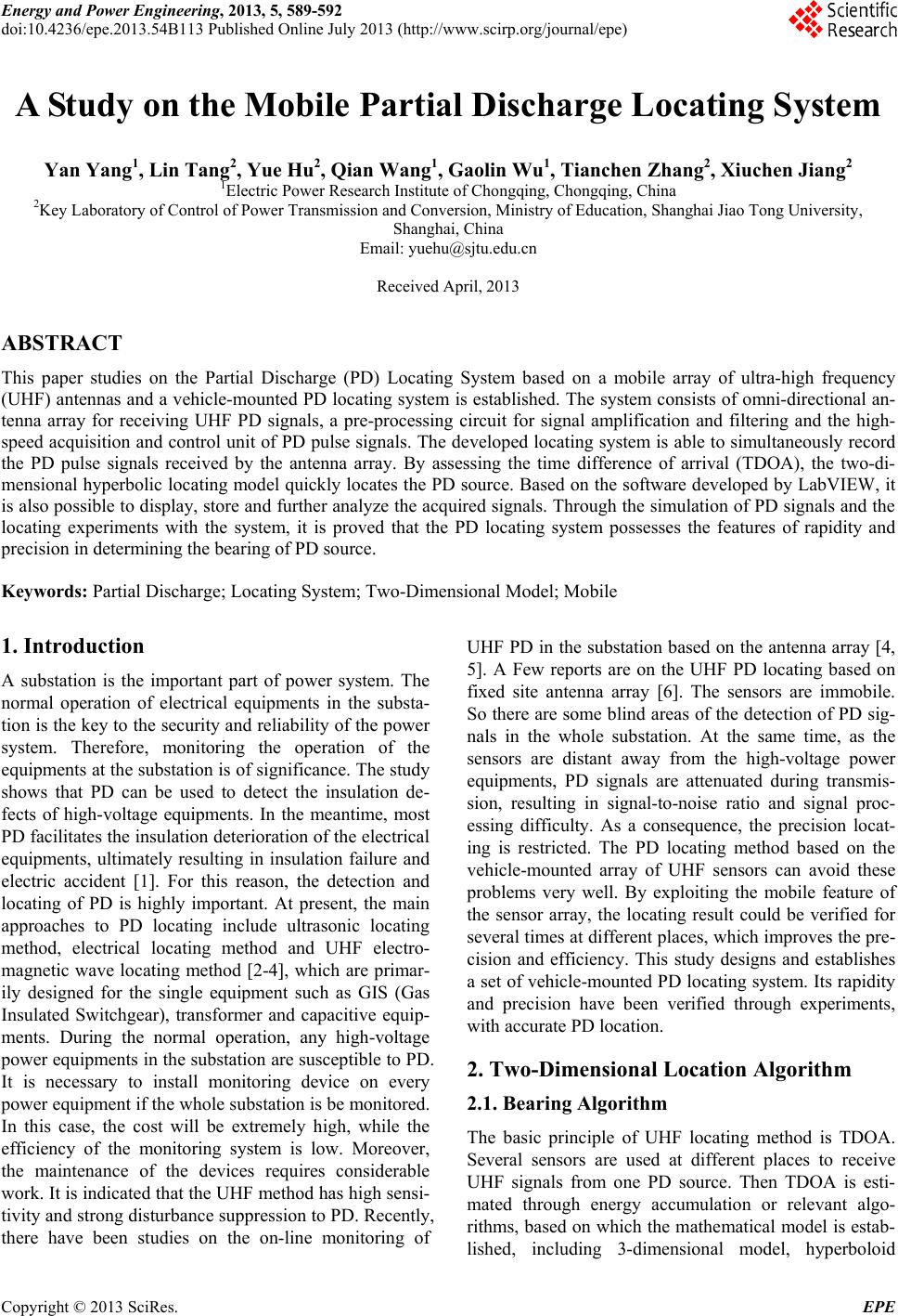
In order to obtain the bearing of PD source, only the
coordinates of X axis and Y axis are required. In the
two-dimensional hyperbolic locating model, it is as-
sumed that the power equipment and the UHF sensors
are in the same plane. As Figure 1 shows, P (x, y) is
taken as the position of PD source and the UHF sensor is
located at i or j (i, j=1,2,3,4). The distance from P, the
1
.
Locating algorithm diagram (top view).
Figure 1. Locating algorithm diagram (top view).
PD source, and the sensor is di, dj. In the process of PD
detection, TDOA at the UHF sensor receiving the UHF
PD signals can be calculated. Assuming the transmission
velocity is constant (velocity of light), the difference of
distance di-dj could be obtained. By making one differ-
ence constant (for example, d1 - d2 is constant, see Equa-
tion (1)), a unique single-branch hyperbolic curve could
be determined. According to the TDOA detected by dif-
ferent arrays of sensors (one array consists of any two
UHF sensors), different single-branch hyperbolic curves
are obtained. Any two single-branch hyperbolic curves,
as shown in Figure 1, could form binary quadratic equa-
tions as Equation (1). Then the two-dimensional coordi-
nates of PD source could be obtained by analytical solu-
tion. By means of coordinate transformation, the bearing
and the radial distance could be known. The six inde-
pendent delta-T calculated from antenna array can de-
termine the quadrant where PD happens. So the other
wrong intersections can be eliminated. Such as, if PD
source discharges in Quadrant I,dealt-T21(which means
T2-T1) must be negative.
(1)
where aij=(di-dj)/2 is length of semi-major axis;
bij2= cij2- aij2 is the square of the length of semi-minor
axis; cij is the focal distance of hyperbola, determined by
the size of antenna array
2.2. Arrival Time Difference Calculation
In the hyperbolic locating model, it can be seen that the
detection method of bearing of PD source is directly
based on TDOA of UHF PD signals. The error of the
calculated TDOA will inevitably affect the precision of
location. The System uses the cross-correlation algorithm
to estimate TDOA [7]. In the calculation of TDOA, it is
assumed that the sampling rate of locating system is
5Gps/s, which means that there is a deviation of sam-
pling interval. As a result, the error of the estimated
TDOA is ±0.2 ns. . When the noise level is high, espe-
cially when the peaks of PD signal are close, the TDOA
calculated by the cross-correlation algorithm will be af-
fected. The PD signal is the pulse signal with short PD
duration. When the noise signal of the wave front and
wave tail is large, mistaken translation points may occur,
leading to maximal correlation coefficient. In order to
obtain a relatively precise TDOA, the system adopts the
strategy of combining hardware filtering with software
de-noising. The hardware filtering is accomplished by
the front-end conditioning circuit. The purpose is to en-
able the sampling system to acquire PD signal during a
single collection task. The front-end conditioning circuit
Copyright © 2013 SciRes. EPE
Y. YANG ET AL. 591
amplifies the PD signal on a specific basis, while attenu-
ating the nose signals. The de-noising with software is
based on self-adaptive wavelet de-noising. Taking the
signal without being contaminated by PD signal as back-
ground noise, it divides the db8 wavelet into 8 layers.
The wavelet threshold is extracted for de-noising of the
original signal (Figure 2). After wavelet de-noising for
PD signal detected at a substation of Sh andong Province,
the result is as shown in Figure 3.
Comparing the signals in Figure 2 and Figure 3, it is
easy to see that the system well retains the PD pulse sig-
nal and removes the background noise. The signal-to-
noise ratio stays relatively high
3. Mobile PD Locating System
According to the two-dimensional bearing locating mod-
el, the vehicle-mounted PD locating system is designed.
The composition of the system and the procedures of
signal processing are shown in F igure 4.
The system mainly consists of:
Figure 2. PD Signal Detected in a Substation of Shandong
Province.
Figure 3. Signal after Wavelet De-noising.
Figure 4. System structure.
1) UHF sensor array: The sensor's response fre-
quency is 0.2 - 3 GHz in order to ensure that the sensor
array could receive all pulse signals emitted by a variety
of PD insulation defects, which produces TDOA. Omni-
directional sensor array includes 4 sensors with 1m dis-
tance between any two. The sensors are arranged in a
rectangular plane.
2) The pre-processing circuit: It is composed of the
same four-channel conditioning circuit which is mainly
for signal amplification and wave filtering. According to
the actual noise frequency spectrum of substation, a
band-pass filter amplifier is designed with amplifier gain
of 40dB. The pass-band range of the filter is adjustable
with bandwidt h of more than 100 MHz.
3) Data acquisition unit: The experimental system is
DP05204 Digital Storage oscilloscope produced by Tek-
tronix. Under four-channel simultaneous sampling, the
highest sampling rate is set as 5Gps/s.
4) Data analysis and control unit: The hardware is
portable computer. The software is developed based on
LabVIEW. It performs the functions of controlling data
acquisition, data analysis and disp lay, PD source locating
and interactive interface.
5) Power supply unit: It adopts the vehicle-mounted
mobile power. Lithium batteries supply DC power to the
pre-processing circuit. At the same time, inverter is used
to provide 220 V AC voltage for oscilloscope. The ca-
pacity of lithium battery is 12 V 100 AH. After being
fully charged, the system is assured to run for more than
8 hours inspecting the substation.
The procedures of signal processing based on the
hardware component are as follows: sensor array re-
ceives the PD signal from the same source. After the am-
plifying and filtering by pre-processing circuit, data ac-
quisition unit then digitizes the signal by pulse triggering.
The recorded UHF PD pulse waveforms of the same
source are then transmitted to the data analysis and con-
trol unit for wavelet de-noising and TDOA calculation.
Then according to the locating model, all calculated val-
ues of TDOA are used for the calculation of the bearing
and distance of PD source.
4. Experiment
The UHF sensor array is installed on roof of the vehicle
through a bracket. By using the simulator of PD at spe-
Copyright © 2013 SciRes. EPE
Y. YANG ET AL.
Copyright © 2013 SciRes. EPE
592
5. Discussion and Conclusions
cific points, the test on the system's performance in lo-
cating is carried out, as shown in Figure 5. This paper designs a vehicle-mounted PD locating sys-
tem for substation based on the UHF method. The hard-
ware unit is built, consisting of UHF sensor array, filter-
ing and amplifying module, high-speed digital storage
oscilloscope, portable computer, LABVIEW interactive
interface and the connecting components between parts.
In the test where PD simulator is used to simulate PD
signal, this system gives a precise locating of PD source.
The reliability and the accuracy of the system in deter-
mining the bearing of PD source are verified. It possesses
a bright future in the application of PD locatio n.
The vehicle-mounted antenna array and interactive in-
terface are shown in Figure 6.
The test data and locating results are shown in Table
1. The results of the test show that the system could pre-
cisely estimate the bearing when locating the PD source
simulated by PD simulator. The error is small, typically
in the range of 4°. The radial distance estimated devi-
ates greatly. So the precision of the locating remains to
be improved.
The two-dimensional hyperbolic locating algorithm
used by the locating system has superiorities in locating
speed and accuracy of bearing determination. However,
it still needs to improve the precision of radial distance
determination. In addition, further analysis of PD signal
which has been collected is needed to realize the classi-
fication and pattern recognition of PD
REFERENCES
Figure 5. Testing scene. (1-antenna array; 2-amplifier &
filter module; 3-high-speed oscilloscope; 4-laptop). [1] S. S. Zhang, J. X. Chen, C .R. Li and H. Lin, “Influ-
ence of Windings on Locating Partial Discharge in
Transformers by Using Ultra-high Frequency Method,”
High Voltage Engineering, Vol. 39, No. 2, 2013, pp.
324-326.
[2] D. J. Li, J. Z. Liang, K. W. Bu, J. G. Yang and Y. M. Li,
“Ultrasonic Detection of Partial Discharge on Typical
Defects in GIS,” High Voltage Apparatus, Vol. 45, No. 1,
2009, pp. 72-74.
Figure 6. Vehicle-mounted Antenna Array and Interactive
Interface. [3] J. F. Gui, W. S. Gao and Z. S. Wu, “Frequency Band of
Pulse Current Method for the Measurment of PD in
Transformer,” High Voltage Engineering, Vol. 31, No. 1,
2005, pp. 45-46.
Table 1. Locating results of the system for PD simulator
and the errors. [4] H .J. Hou, G. H. Sheng, P. Q. Miao, X. W. Li, Y. Hu and
X. C. Jiang, “Partial Discharge Location Based on Radio
Frequency Antenna Array in Substation,” High Voltage
Engineering, Vol. 38, No. 6, 2012, pp. 1334-1340.
Position of PD source Locating results Error
No. Bearing
Distance
/m Bearing /°Distance
/m Dis-
tance/m Distance
/m
1 122 6.72 120.856.39 -1.15 -4.91
2 106 4.90 104.543.53 -1.46 -27.96
3 40 4.25 38.48 4.48 -1.52 +5.41
4 -4 5.13 -3.76 1.1 0.24 -78.56
5 315.00 14.14 315.1712.26 0.17 -13.30
6 326.31 18.03 327.0735.71 0.76 +98.06
7 330.43 22.36 326.5935.9 -3.84 +60.55
8 337.38 26.00 333.6433.45 -3.74 +28.65
[5] J. M. Philip, I. E. Portugues and I. A. Glover, “Radiomet-
ric Location of Partial Discharge Sources on Energized
High-Voltage Plant,” IEEE Transactions on Power De-
livery, Vol. 20, NO. 3, 2005, pp. 2264-2272.
doi:10.1109/TPWRD.2004.843397
[6] E. P. Iliana and J. M. Philip, “RF-Based Partial Discharge
Early Warning System for Air-Insulated Substation,”
IEEE Transactions on Power Delivery, Vol. 24, NO. 1,
2009, pp. 20-29. doi:10.1109/TPWRD.2008.2005464
[7] J. Tang and J. Chen, “Time Difference Algorithm Based
on Energy Relevant Search in PD Location of Power
Transformer,” Master Thesis, College of Electrical Engi-
neering of Chongqing University, Chongqing, 2009