Energy and Power Engineering, 2013, 5, 579-583
doi:10.4236/epe.2013.54B111 Published Online July 2013 (http://www.scirp.org/journal/epe)
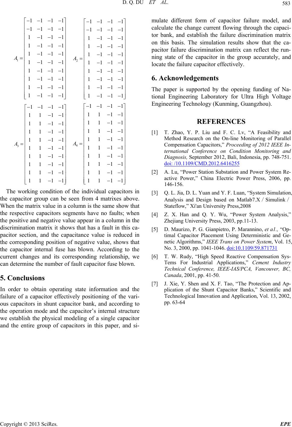
Fault Location Method and Simulation Analysis of
Parallel Compensating Capacitors
Daquan Du1, Na Zheng2, Zhiming Su3
1Hebei Electric Power Research Institute, Shijiazhuang of Hebei, China
2Hebei Shijiazhuang Power Supply Company, Shijiazhuang of Hebei, China
3School of Electrical and electronic engineering, North China Electric Power University, Baoding of Hebei, China
Email: 13903110376@126.com
Received March, 2013
ABSTRACT
At present, the operational parallel compensating capacitors can only through the protection action for the information,
so we can‘t location the fault capacitor. In order to obtain every parallel capacitor running status information and
meanwhile according to internal structure and the operation mode of film capacitor, this paper established the physical
model on the single capacitor and the capacitors and simulated different forms of capacitor fault model and calculated
currents changes which flow through the capacitor in every group. According to the above situation, we established
fault criterion matrix of capacitors. The simu lation results show that the fault criterion matrix can reflect capacitor run-
ning state information accurately, and it positioned fault capacitor effectively.
Keywords: Parallel Capacitor; Physical Model; Fault Locatio n; Fault Matrix
1. Introduction
As a kind of very important reactive power compensation
equipment, capacitor improved the power system struc-
ture and the power quality. The stable operation of ca-
pacitors is a very important guarantee for the power sys-
tem security.
At present, the transformer substation under the juris-
diction of the power supply company, which has large
numbers of capacitor. So it is difficult to monitor single
capacitor’s electric capacity effectively in the operation
and maintenance. When the capacitor failure o ccurs, only
relying on capacitor protection device movement, this
method is an afterthought method, and only reflects the
fault information of the capacitors. Location the fault
capacitor need for detected individually[1-3].
Currently, the running parallel capacitor is lack of ef-
fective online testing means. Reference [4] applied high
potentials in taking energy and wireless synchronization
acquisition and transmission technology to design a par-
allel capacitor’s capacitance online monitoring system.
Based on th e each curr ent f low through capacitor, we can
realize the change trend of every capacitor’s capacitance.
In order to obtain the capacitor in the parallel capacitor
banks operating status information and locate on the fault
capacitor effectively, this paper modeled a single capaci-
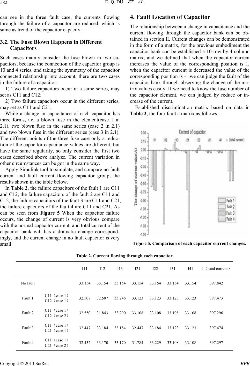
tor and the entire group of capacitors physical model,
which according to the internal structure of the film ca-
pacitors and field operation. We simulated different
forms of capacitor fault model and calculated currents
changes which flow through the capacitor in every group.
According to the above situation, we established fault
criterion matrix of capacitors. The simulation results
show that the fault criterion matrix can reflect capacitor
running state information accurately, and it positioned
fault capacitor effectively.
2. The Internal Structure and Operation
Mode of the Parallel Capacitor
Currently, film capacitors have been widely applied be-
cause of their excellent performance in the power sys-
tem .The internal core electrode of a film capacitor is a
metal foil, and use polyethylene, polypropylene, poly-
styrene or polycarbonate plastic film wound into a cylin-
drical shape from the overlap of the ends, then through
Press-fit, connection, packaging, packing, capping means
to create .Internal core of the single capacitor connected
M and N series. In the actual running of the site, the
three-phase connection of the parallel capacitor bank is
generally star wiring. In each phase, it also takes the
form of capacitors in series and parallel combinations to
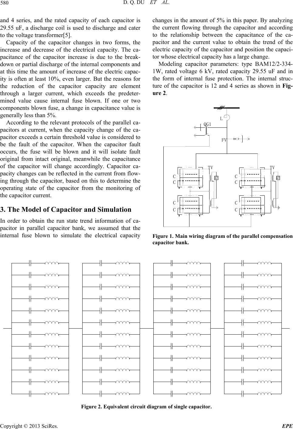
meet the requirements of various parameters. Figure 1 is
a common wiring for parallel compensation capacitor,
the double-star wiring, the neutral point ungrounded. In
each phase, the connection of each star capacitor is 10
Copyright © 2013 SciRes. EPE