Paper Menu >>
Journal Menu >>
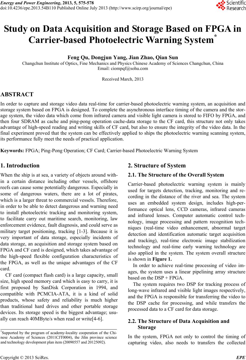 Energy and Power Engineering, 2013, 5, 575-578 doi:10.4236/epe.2013.54B110 Published Online July 2013 (http://www.scirp.org/journal/epe) Study on Data Acquisition and Storage Based on FPGA in Carrier-based Photoelectric Warning System* Feng Qu, Dongjun Yang, Jian Zhao, Qian Sun Changchun Institute of Optics, Fine Mechanics and Physics Chinese Academy of Sciences Changchun, China Email: ciompqf@sohu.com Received March, 2013 ABSTRACT In order to capture and storage video data real-time for carrier-based photoelectric warning system, an acquisition and storage system based on FPGA is designed. To complete the asynchronous interface timing of the camera and the stor- age system, the video data which come from infrared camera and visible light camera is stored to FIFO by FPGA, and then four SDRAM as cache and ping-pong operation cache-data storage to the CF card, this structure not only takes advantage of high-speed readin g and writing skills of CF card, but also to ensure the integ rity of the video data. In the final experiment proved that the system can be effectively applied to ships the photoelectric warning scanning system, its performance fully meet the needs of practical application. Keywords: FPGA; Ping-Pong Operation; CF Card; Carrier-based Photoelectric Warning System 1. Introduction When the ship is at sea, a variety of objects around with- in a certain distance including other vessels, offshore reefs can cause some potentially dangerous. Especially in some of dangerous waters, there are a lot of pirates, which is a larger threat to commercial vessels. Therefor e, in order to be able to detect dang erous and warning need to install photoelectric tracking and monitoring system, to facilitate carry out maritime search, monitoring, law enforcement evidence, fault diagnosis, and could serve as military target positioning, tracking [1-3]. Because it is very important of data storage, especially incidents of data storage, an acquisition and storage system based on FPGA and CF card is designed, which takes advantage of the high-speed flexible configuration characteristics of the FPGA, as well as the unique advantages of the CF card. CF card (compact flash card) is a large capacity, small size, high speed memory card which is easy to carry, it is first proposed by SanDisk Corporation in 1994, and compatible with PCMCIA-ATA, it is a kind of solid products, whose safety and reliability is much higher than traditional hard drives and other portable storage devices. Its storage speed is the biggest advantage; usu- ally can reach 40MByte/s when read or write[4-6]. 2. Structure of System 2.1. The Structure of the Overall System Carrier-based photoelectric warning system is mainly used for targets detection, tracking, monitoring and re- cording in the distance of the river and sea. The system uses an embedded system design, includes high-per- formance optical lens, CCD cameras, infrared cameras and infrared lenses. Computer automatic control tech- nology, image processing and pattern recognition tech- niques (real-time video enhancement, abnormal target detection and identification automatic target acquisition and tracking), real-time electronic image stabilization technology and real-time early warning technology are also applied in the system. The system overall structure is shown in Figure 1 . In order to achieve real-time processing of video im- ages, the system uses a linear pipelining array structure based on t he DSP + FPGA. The system requires two DSP for tracking process of long-wave infrared and visible light images respectively, and the FPGA is responsible for transferring the video to the DSP cache for processing, and while transfers the processe d d ata to a CF car d for data sto ra ge. 2.2. The Structure of Data Acquisition and Storage *Supported by the program of academy-locality cooperation of the Chi- nese Academy of Sciences (2011CJT0004), the Jilin province science and technology development plan item (20090557 and 20125092). In the system, FPGA not only to control the timing of capturing video, also needs to transfers the collected Copyright © 2013 SciRes. EPE 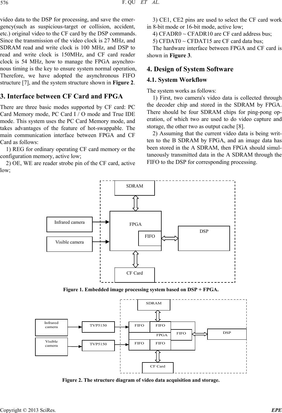 F. QU ET AL. 576 video data to the DSP for processing, and save the emer- gency(such as suspicious-target or collision, accident, etc.) original video to the CF card by the DSP commands. Since the transmission of the video clock is 27 MHz, and SDRAM read and write clock is 100 MHz, and DSP to read and write clock is 150MHz, and CF card reader clock is 54 MHz, how to manage the FPGA asynchro- nous timing is the key to ensure system normal operation, Therefore, we have adopted the asynchronous FIFO structure [7], and the system structure shown in Figur e 2. 3. Interface between CF Card and FPGA There are three basic modes supported by CF card: PC Card Memory mode, PC Card I / O mode and True IDE mode. This system uses the PC Card Memory mode, and takes advantages of the feature of hot-swappable. The main communication interface between FPGA and CF Card as follows: 1) REG for ordinary operating CF card memory or the configuration memory, active low; 2) OE, WE ar e reader str obe pin of the CF car d, active low; 3) CE1, CE2 pins are used to select the CF card work in 8-bit mode or 16-bit mode, active low; 4) CFADR0 ~ CFADR10 are CF card address bus; 5) CFDAT0 ~ CFDAT15 are CF card data bus; The hardware interface between FPGA and CF card is shown in Figure 3. 4. Design of System Software 4.1. System Workflow The system works as follows: 1) First, two camera's video data is collected through the decoder chip and stored in the SDRAM by FPGA. There should be four SDRAM chips for ping-pong op- eration, of which two are used to do video capture and storage, the other two as output cache [8]. 2) Assuming that the current video data is being writ- ten to the B SDRAM by FPGA, and an image data has been stored in the A SDRAM, then FPGA should simul- taneously transmitted data in the A SDRAM through the FIFO to the DSP for corresponding processing. DSP SDRAM CF Card FPGA In frared cam era Visible camera FIFO Figure 1. Embedded image proce ssing system based on DSP + FPGA. SDRAM CF Card FPGA FIFO DSP FIFO FIFO FIFO FIFO TVP5150 TVP5150 Infrared camera Visible camera Figure 2. The structure diagram of video data acquisition and storage. Copyright © 2013 SciRes. EPE 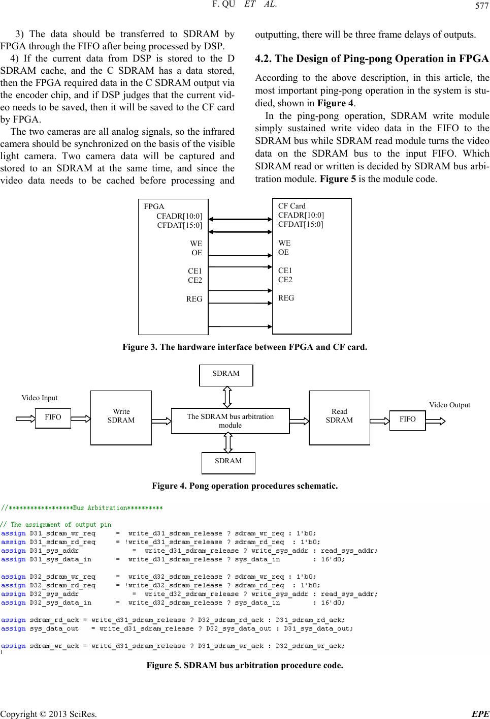 F. QU ET AL. 577 3) The data should be transferred to SDRAM by FPGA through the FIFO after being processed by DSP. 4) If the current data from DSP is stored to the D SDRAM cache, and the C SDRAM has a data stored, then the FPGA required data in the C SDRAM outpu t via the encoder chip, and if DSP judges that the current vid- eo needs to be saved, then it will be saved to the CF card by FPGA. The two cameras are all analog signals, so the infrared camera should be synchronized on the basis of the visible light camera. Two camera data will be captured and stored to an SDRAM at the same time, and since the video data needs to be cached before processing and outputting, there will be three frame delays of outputs. 4.2. The Design of Ping-pong Operation in FPGA According to the above description, in this article, the most important ping-pong operation in the system is stu- died, shown in Figure 4. In the ping-pong operation, SDRAM write module simply sustained write video data in the FIFO to the SDRAM bus while SDRAM read module turns the video data on the SDRAM bus to the input FIFO. Which SDRAM read or written is decided by SDRAM bus arbi- tration module. Figure 5 is the module code. FPGA CFADR[10:0] CFDAT[15:0] WE OE CE1 CE2 REG CF Card CFADR[10:0] CFDAT[15:0] WE OE CE1 CE2 REG Figure 3. The hardware interface between FPGA and CF card. FIFO Write SDRAM The SDRAM bus arbitration module SDRAM SDRAM Read SDRAM FIFO Video Output Video Input Figure 4. Pong operation procedures schematic. Figure 5. SDRAM bus arbitr ation pr oc e dur e code. Copyright © 2013 SciRes. EPE 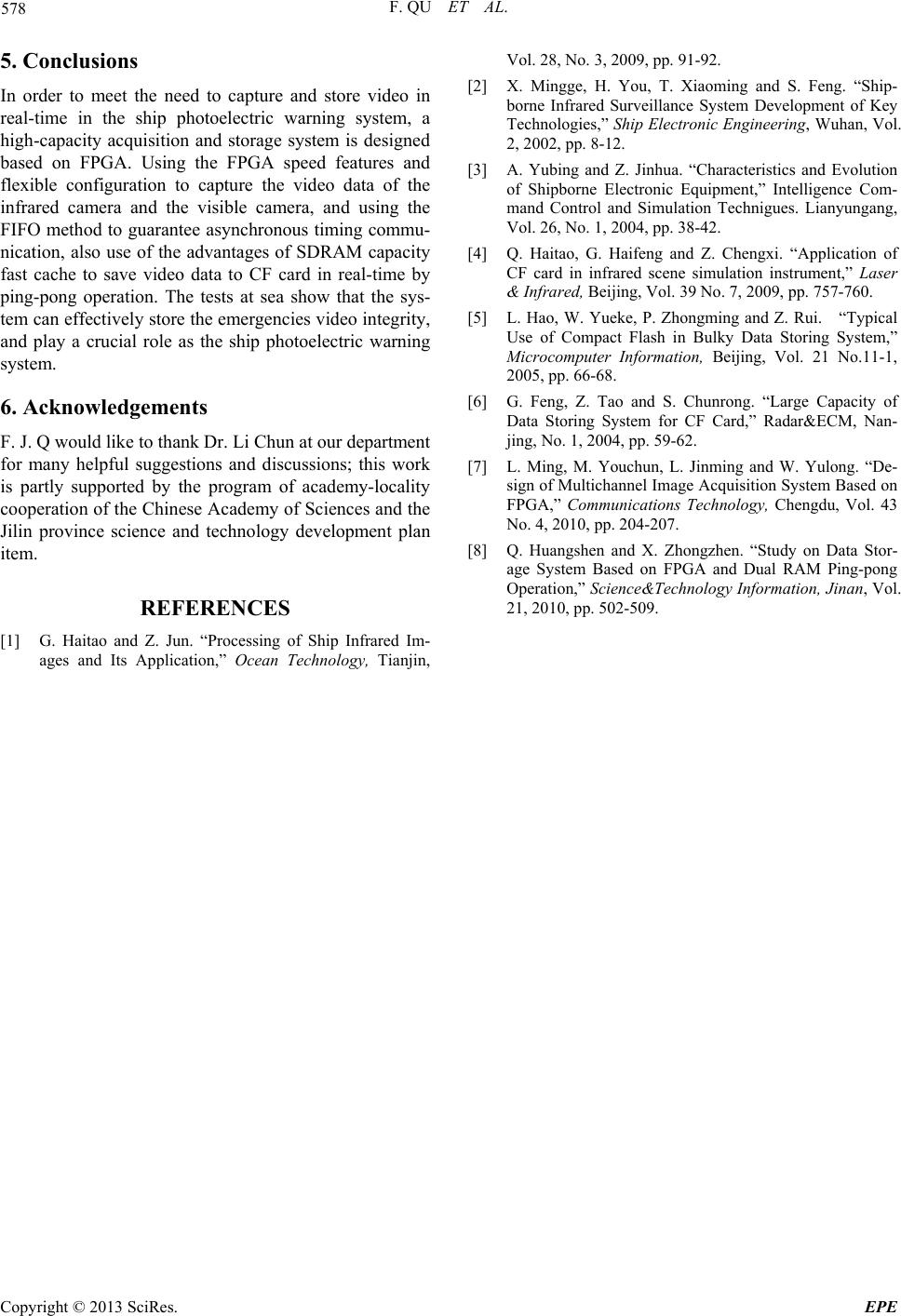 F. QU ET AL. 578 5. Conclusions In order to meet the need to capture and store video in real-time in the ship photoelectric warning system, a high-capacity acquisition and storage system is designed based on FPGA. Using the FPGA speed features and flexible configuration to capture the video data of the infrared camera and the visible camera, and using the FIFO method to guarantee asynchronous timing commu- nication, also use of the advantages of SDRAM capacity fast cache to save video data to CF card in real-time by ping-pong operation. The tests at sea show that the sys- tem can effectively store the emergencies video integ rity, and play a crucial role as the ship photoelectric warning system. 6. Acknowledgements F. J. Q would like to thank Dr. Li Chun at our department for many helpful suggestions and discussions; this work is partly supported by the program of academy-locality cooperation of the Chinese Academy of Sciences and the Jilin province science and technology development plan item. REFERENCES [1] G. Haitao and Z. Jun. “Processing of Ship Infrared Im- ages and Its Application,” Ocean Technology, Tianjin, Vol. 28, No. 3, 2009, pp. 91-92. [2] X. Mingge, H. You, T. Xiaoming and S. Feng. “Ship- borne Infrared Surveillance System Development of Key Technologies,” Ship Electronic Engineering, Wuhan, Vol. 2, 2002, pp. 8-12. [3] A. Yubing and Z. Jinhua. “Characteristics and Evolution of Shipborne Electronic Equipment,” Intelligence Com- mand Control and Simulation Technigues. Lianyungang, Vol. 26, No. 1, 2004, pp. 38-42. [4] Q. Haitao, G. Haifeng and Z. Chengxi. “Application of CF card in infrared scene simulation instrument,” Laser & I nfrar ed, Beijing, Vol. 39 No. 7, 2009, pp. 757-760. [5] L. Hao, W. Yueke, P. Zhongming and Z. Rui. “Typical Use of Compact Flash in Bulky Data Storing System,” Microcomputer Information, Beijing, Vol. 21 No.11-1, 2005, pp. 66-68. [6] G. Feng, Z. Tao and S. Chunrong. “Large Capacity of Data Storing System for CF Card,” Radar&ECM, Nan- jing, No. 1, 2004, pp. 59-62. [7] L. Ming, M. Youchun, L. Jinming and W. Yulong. “De- sign of Multichannel Image Acquisition System Based on FPGA,” Communications Technology, Chengdu, Vol. 43 No. 4, 2010, pp. 204-207. [8] Q. Huangshen and X. Zhongzhen. “Study on Data Stor- age System Based on FPGA and Dual RAM Ping-pong Operation,” Science&Technology Information, Jinan, Vol. 21, 2010, pp. 502-509. Copyright © 2013 SciRes. EPE |