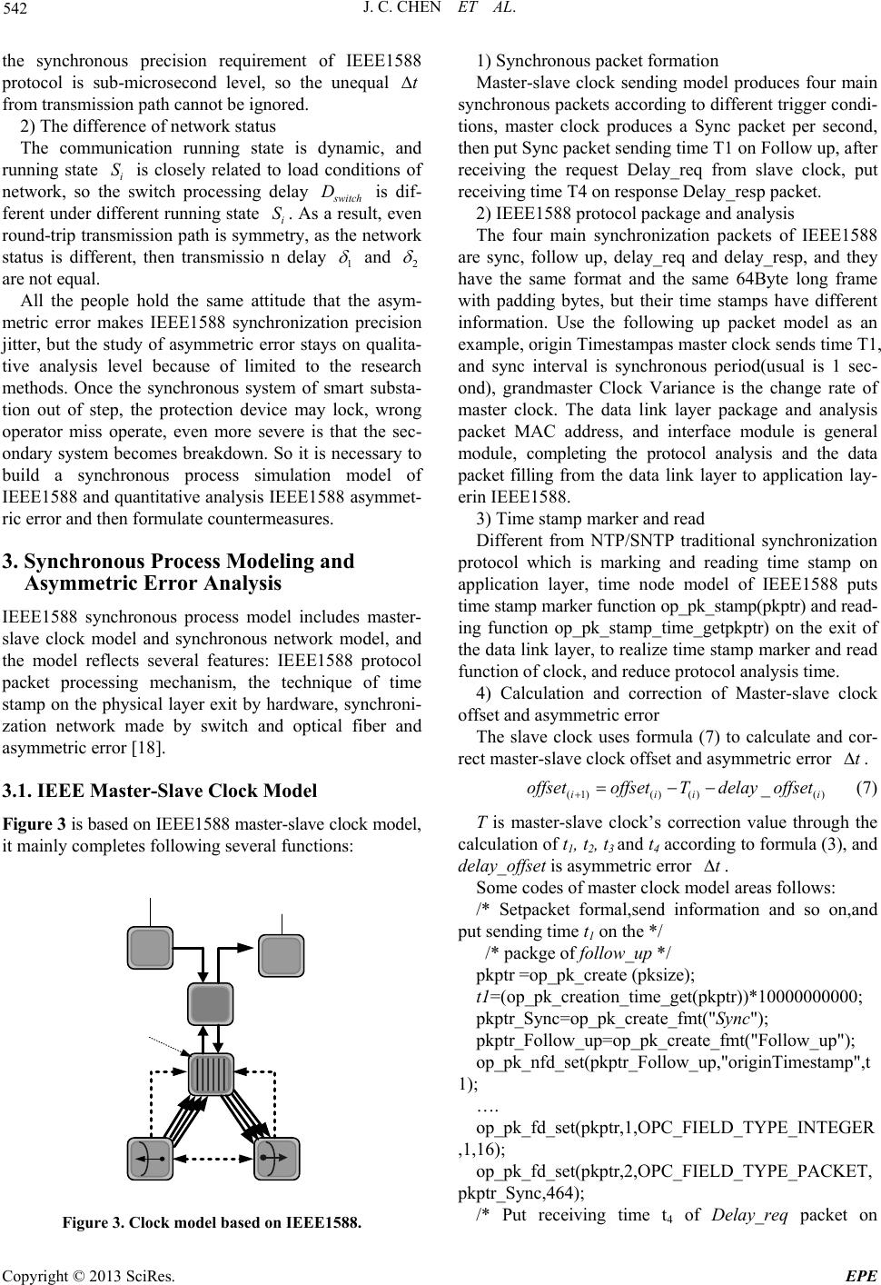
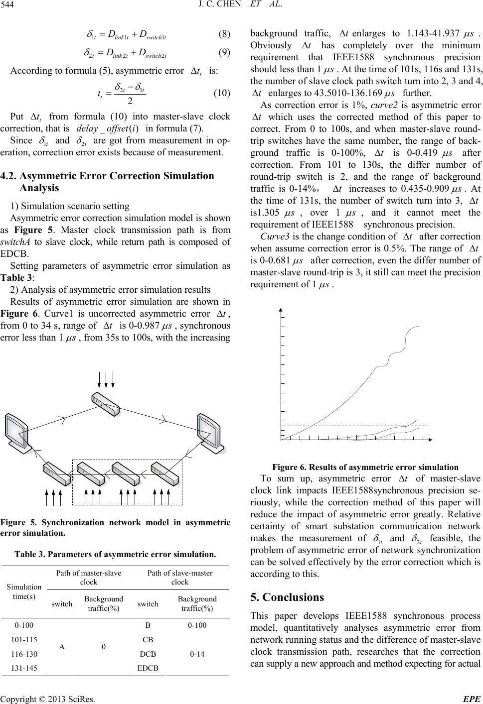
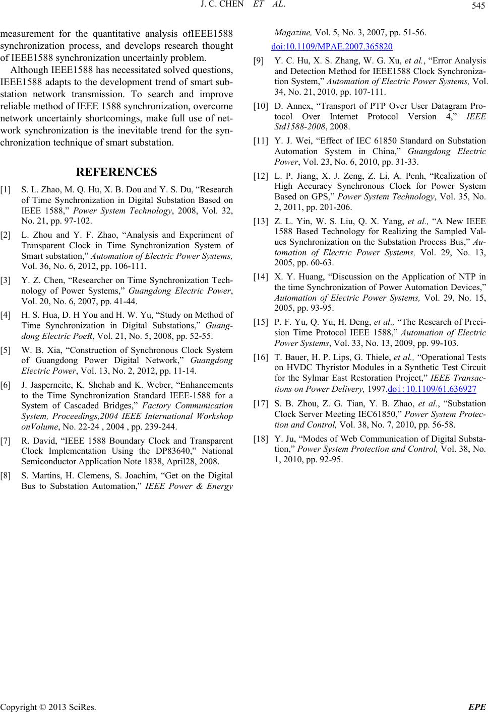
 Energy and Power Engineering, 2013, 5, 540-545 doi:10.4236/epe.2013.54B103 Published Online July 2013 (http://www.scirp.org/journal/epe) Modeling of IEEE1588 on OPNET and Analysis of Asymmetric Synchronizing Error in Smart Substation Jiongcong Chen1, Haizhu Wang2, Chunchao Hu1, Ka i Ma1, Zexiang Cai2 1Electric Power Research Institute, Guangdong Power Grid Corporation, Guangzhou, China 2South China University of Technology, Guangzhou, China Email: 20801244@qq.com Received March, 2013 ABSTRACT The IEEE1588 network time synchronization, matched with smart substation information network transmission, is be- coming the next generation advanced data synchronization of the smart substation. It is known that the inherent asym- metry error of the network synchronization approach in the smart substation is highlighted, which is concerned particu- larly. This paper models the synchronization process of the IEEE1588 based on the communication simulation software of OPNET Modeler. Firstly, it builds the models of master-slave clock, IEEE1588 protocol and network synchroniza- tion model, and analyzes the composition and influencing factors of the asymmetry error. Secondly, it quantitatively analyzes the influence of the synchronous asymmetric error of the IEEE1588 affected by the network status differences and the clock synchronization signal transmission path differences. Then its correction method is analyzed, in order to improve the IEEE1588 synchronization reliability and gives the solutions to its application in smart substation. Keywords: Smart Substation; IEEE1588; Synchronization; Asymmetric Error 1. Introduction As the important node of the smart grid, the smart sub- station based on network communication provides grid application oriented integration data platform, its biggest feature and advantage is information sharing [1-3]. The synchronization of high precision data is the important premise and basic properties to realize information shar- ing. Application system such as relay protection, SCA- DA, PMU and so on has a high requirement on the data synchronization which is paid much attention as the core problem of smart substation technology [4-6]. At present, the smart substation data synchronization usually adopts IRIG-B, and uses point-to-point link with exclusive fiber optic, sending the unidirectional synchro- nization signal. This type of flow reliability conflicts with the network information transmission mode of smart substation [7-8]. IEEE1588 as precision clock synchroni- zation protocol matches with Intelligent substation net- work transmission mode based on IEC61850 [9], can share network resources with other packet, and elimi- nates the timestamp mark error of NTP/SNTP protocol mode and its synchronization is accurate to sub-micro- second, which is becoming the next generation synchro- nization mode of the smart substation, with good devel- opment prospects. At the same time, with the inherent defect of uncertain network synchronization, synchronized asymmetry error may occur in the synchronization of IEEE1588 because of differences running state and transmission path in the network. Under the high data synchronization requirements of smart substation, the issue becomes more prominent [10-12]. At present, due to the lack of quantitative analy -sis tools and methods, the study of IEEE1588 is limited to the field test, the study on the forming mechanism, influence degree and countermeasure of the dissymmet- ric error is nearly in a gap, which limits its popularization and application [13-14]. This paper develops a IEEE1588 synchronization proc- ess modeling of smart substation with a communication simulation software named OPNET Modeler, and analy- ses the differences of network status and the master-slave clock synchronization signal transmission path quantita- tively [15], then studies the influence on IEEE1588 synchronous asymmetry error[16], as also as its correct- ing method. 2. Asymmetric Synchronizing Error IEEE1588 precision clock synchronization protocol was promulgated by the IEEE standard committee in 2002, which is to meet the high-precision requirement of the measurement and control applications in a distributed Copyright © 2013 SciRes. EPE  J. C. CHEN ET AL. 541 network of timing synchronization. It’s a brand-new at- tempt to introduce IEEE1588 into power domain that is consistent with smart substation network transmission, and is beneficial to take advantage of information sharing. But as a network synchronization mode, the problem of uncertainty is also prominent which needs to be studied in depth. 2.1. IEEE 1588 Protocol and Synchronization Process 1) IEEE 1588 protocol feature IEEE1588 protocol is a distributed network synchro- nization protocol, and it doesn’t need networking singly [17]. It can share hardware resources on network, and chooses multiple transmission paths flexibly, also can get the real-time status of other nodes on network. It ensures the reliability of the synchronization system. Traditional network synchronization time stamp was performed by the software, and the position of time stamp is on application layer, so the message parsing and packaging processing delay constitute a part of synchro- nization error. As IEEE1588 Protocol time stamps on physical layer exit by hardware using the technology of accessing MAC by Ethernet media, which eliminates part error of time delay, as shown in Figure 1. 2) Synchronization process IEEE1588 synchronization process is shown in Figure 2. Figure 1. Time stamp of network synchronization. Figure 2. Synchronization process of IEEE1588. Assuming that the master clock and the slave clock deviation is offset, that is offset = tslave - tmaster , the slave clock at the local time t1 sends synchronization request packets to the master clock, the master clock receives synchronization request packets at the local time t2. As- suming transmission delay from the slave clock to the master clock is 1 , so 21 tt offset1 (1) The master clock sends synchronization packets to the slave clock at t3, and the synchronization packet includes two time scales as t2 and t3. The slave clock receives the synchronization packet at t4. If transmission delay from the master clock to the slave clock is 2 , so 43 tt offset2 (2) All t1, t2, t3 and t4 are known quantities in formula (1) and (2), but offset, 1 and 2 are unknown quantities. Assumes 1 = 2 , so the slave clock can solve and correct the time error offset based on the formula (1), so 21 43 ( 2 tt tt offset ) (3) 2.2. The Influences of IEEE1588 Asymmetric Error The importance assumption of IEEE1588 synchroniza- tion is round-trip transmission path symmetry, transmis- sion delay 1 = 2 , since the differences in both net- work status and transmission path dynamics, transmis- sion delay 1 and 2 generally are not equal, which cannot be deleted directly, so formula (3) should be cor- rected as: 21432 1 2 tt tt offset (4) 21 2 t (5) t is asymmetric error, the influences of IEEE1588 asymmetric error mainly includes: 1) The difference of transmission path Transmission delay is composed of link transmis- sion delay and switch transmission delay link D witch D, so link switch DD (6) Synchronous packet is stored and forwarded by the switch address analytical table dynamically, as round-trip transmission path may be different when the synchronous packet passes switch and link, link and D witch are not symmetrical generally. The transfer rate of optical fiber link is 2/3 of velocity of light, that is to say the transmission delay of one 1000-meter link is 5μs. A switch packet processing delay is microsecond level, but D Copyright © 2013 SciRes. EPE  J. C. CHEN ET AL. 542 the synchronous precision requirement of IEEE1588 protocol is sub-microsecond level, so the unequal t from transmission path cannot be ignored. 2) The difference of network status The communication running state is dynamic, and running state i is closely related to load conditions of network, so the switch processing delay S witch is dif- ferent under different running state i. As a result, even round-trip transmission path is symmetry, as the network status is different, then transmissio n delay D 1 S and 2 are not equal. All the people hold the same attitude that the asym- metric error makes IEEE1588 synchronization precision jitter, but the study of asymmetric error stays on qualita- tive analysis level because of limited to the research methods. Once the synchronous system of smart substa- tion out of step, the protection device may lock, wrong operator miss operate, even more severe is that the sec- ondary system becomes breakdown. So it is necessary to build a synchronous process simulation model of IEEE1588 and quantitative analysis IEEE1588 asymmet- ric error and then formulate countermeasures. 3. Synchronous Process Modeling and Asymmetric Error Analysis IEEE1588 synchronous process model includes master- slave clock model and synchronous network model, and the model reflects several features: IEEE1588 protocol packet processing mechanism, the technique of time stamp on the physical layer exit by hardware, synchroni- zation network made by switch and optical fiber and asymmetric error [18]. 3.1. IEEE Master-Slave Clock Model Figure 3 is based on IEEE1588 master-slave clock model, it mainly completes following several functions: Figure 3. Clock model based on IEEE1588. 1) Synchronous packet formation Master-slave clock sending model produces four main synchronous packets according to different trigger condi- tions, master clock produces a Sync packet per second, then put Sync packet sending time T1 on Follow up, after receiving the request Delay_req from slave clock, put receiving time T4 on response Delay_resp packet. 2) IEEE1588 protocol package and analysis The four main synchronization packets of IEEE1588 are sync, follow up, delay_req and delay_resp, and they have the same format and the same 64Byte long frame with padding bytes, but their time stamps have different information. Use the following up packet model as an example, origin Timestampas master clock sends time T1, and sync interval is synchronous period(usual is 1 sec- ond), grandmaster Clock Variance is the change rate of master clock. The data link layer package and analysis packet MAC address, and interface module is general module, completing the protocol analysis and the data packet filling from the data link layer to application lay- erin IEEE1588. 3) Time stamp marker and read Different from NTP/SNTP traditional synchronization protocol which is marking and reading time stamp on application layer, time node model of IEEE1588 puts time stamp marker function op_pk_stamp(pkptr) and read- ing function op_pk_stamp_time_getpkptr) on the exit of the data link layer, to realize time stamp marker and read function of clock, and reduce protocol analysis time. 4) Calculation and correction of Master-slave clock offset and asymmetric error The slave clock uses formula (7) to calculate and cor- rect master-slave clock offset and asymmetric error t . (1)()()() _ iii offsetoffsetTdelay offset i (7) T is master-slave clock’s correction value through the calculation of t1, t2, t3 and t4 according to formula (3), and delay_offset is asymmetric error . t Some codes of master clock model areas follows: /* Setpacket formal,send information and so on,and put sending time t1 on the */ /* packge of follow_up */ pkptr =op_pk_create (pksize); t1=(op_pk_creation_time_get(pkptr))*10000000000; pkptr_Sync=op_pk_create_fmt("Sync"); pkptr_Follow_up=op_pk_create_fmt("Follow_up"); op_pk_nfd_s et(pkptr_Fo llow_up,"o riginTimesta mp",t 1); …. op_pk_fd_set(p kptr,1,OPC_FI ELD_TYPE_INTEGER ,1,16); op_pk_fd_set(p kptr,2,OPC_FIELD_ TYPE_PACKET, pkptr_Sync,464); /* Put receiving time t4 of Delay_req packet on Copyright © 2013 SciRes. EPE  J. C. CHEN ET AL. 543 response packetDelay_resp. */ pkptr = op_pk_get (op_intrpt_strm ()); op_pk_stamp(pkptr); t4=(op_pk_stamp_time_get(pkptr))*10000000000; op_pk_nfd_set( pkptr_Delay_resp,"or iginTimestamp",t 4); Some codes of slave clock model areas follows: /* Calculate and correct master-slave clock offset and asymmetric errordelay_offset. */ T=((t2-t1)- (t4-t3))*0.5; delay_offset=((t2-t1)+(t4-t3)) *0.5; offset=offset-T- delay_offset; 3.2. Network Synchronization Model Network synchronization model includes running status network model, transmission path network model, the switch with 500000 p/s processing capacity and the100M optical fiber link, shown as Figure 4. In Figure 4(a), to observe the transmission delay with different network running status, inject background traffic into switch. In Figure 4(b), to observe the transmission delay with different transmission path, increasing the number of switch from 0 to 3 on master-slave synchronous packet transmission path. Different network running status 3.3. Asymmetric Error Simulation Table 1 is the performance of transmission delay, injects different background traffic to the switch. When back- ground traffic is 25%, transmission delay is 262.993 , which costs 1 more compared to transmission delay without background traffic. Transmission delay becomes 2.667 when background traffic is 40%. When back- ground traffic increases to 95%, transmission delay is 337.993 . Value of transmission delay varies from 0.211 to 76 on different background traffic, and it enlarges constant. Asymmetric error fromdifferent network running status couldnot be ignored. t Figure 4. Netw or k synchronization model. 2) Different transmission path From Table 2, when the number of switch increases one more, transmission delay will increase 87. So when configuration of communication network switch change and master-slave clock round-trip transmission path differ one or one more switch, correction of asymmetric error ∆t must exist. So assumption of master-slave clock round-trip trans- mission path is equal exists defect, asymmetric error from different network status and transmission path should be a necessary link of synchronous correction. 4. Asymmetric Error Correction There are some differences between smart substation communication network and general LAN: 1) the struc- ture of network is simple. Configuration of smart substa- tion secondary system is normative according to voltage level, the number of devices are limited, switches are no more than four in general; 2) Traffic flow is specific. All automatic business such as measurement, protection, test and control and etc. have their corresponding SV/GO- OSE/MMS/Synchronization information flow, and the feature of information flow is specific, little uncertain flow. Specific feature of smart substation communication network makes asymmetric error correction feasible. 4.1. Asymmetric Error Correction Method Assuming at time t, master-slave clock transmission de- lay is measured by network monitoring device. Table 1. Impact of background traffic on transmission de- lay. Background traffic Delay(μs) 0% 261.993 5% 262.204 10% 262.438 20% 262.993 40% 264.660 80% 277.993 95% 337.993 Table 2. Impact of path on transmission delay. The number of switch Delay(μs) The increase of transmission delay(μs) 0 88.553 / 1 176.207 87.654 2 261.993 85.786 3 349.145 87.152 Copyright © 2013 SciRes. EPE  J. C. CHEN ET AL. 544 11tlinktswitch t DD 1 (8) 22tlinktswitch t DD 2 (9) According to formula (5), asymmetric error t t is: 21 2 t t tt (10) Put t from formula (10) into master-slave clock correction, that is t ()delayoffset i in formula (7). Since 1t and 2t are got from measurement in op- eration, correction error exists because of measurement. 4.2. Asymmetric Error Correction Simulation Analysis 1) Simulation scenario setting Asymmetric error correction simulation model is shown as Figure 5. Master clock transmission path is from switchA to slave clock, while return path is composed of EDCB. Setting parameters of asymmetric error simulation as Table 3: 2) Analysis of asymmetric error simulation results Results of asymmetric error simulation are shown in Figure 6. Curve1 is uncorrected asymmetric error t , from 0 to 34 s, range of is 0-0.987 t , synchronous error less than 1 , from 35s to 100s, with the increasing Figure 5. Synchronization network model in asymmetric error simulation. Table 3. Parameters of asymmetric error simulation. Path of master-slave clock Path of slave-master clock Simulation time(s) switch Background traffic(%) switch Background traffic(%) 0-100 B 0-100 101-115 CB 116-130 DCB 131-145 A 0 EDCB 0-14 background traffic, t enlarges to 1.143-41.937 . Obviously t has completely over the minimum requirement that IEEE1588 synchronous precision should less than 1 . At the time of 101s, 116s and 131s, the number of slave clock path switch turn into 2, 3 and 4, t enlarges to 43.5010-136.169 further. As correction error is 1%, curve2 is asymmetric error t which uses the corrected method of this paper to correct. From 0 to 100s, and when master-slave round- trip switches have the same number, the range of back- ground traffic is 0-100%, is 0-0.419 t after correction. From 101 to 130s, the differ number of round-trip switch is 2, and the range of background traffic is 0-14%, t increases to 0.435-0.909 . At the time of 131s, the number of switch turn into 3, t is1.305 , over 1 , and it cannot meet the requirement of IEEE1588 synchronous precision. Curve3 is the change condition of after correction when assume correction error is 0.5%. The range of tt is 0-0.681 after correction, even the differ number of master-slave round-trip is 3, it still can meet the precision requirement of 1 . Figure 6. Results of asymmetric error simulation To sum up, asymmetric error of master-slave clock link impacts IEEE1588synchronous precision se- riously, while the correction method of this paper will reduce the impact of asymmetric error greatly. Relative certainty of smart substation communication network makes the measurement of 1t t and 2t feasible, the problem of asymmetric error of network synchronization can be solved effectively by the error correction which is according to this. 5. Conclusions This paper develops IEEE1588 synchronous process model, quantitatively analyses asymmetric error from network running status and the difference of master-slave clock transmission path, researches that the correction can supply a new approach and method expecting for actual Copyright © 2013 SciRes. EPE  J. C. CHEN ET AL. Copyright © 2013 SciRes. EPE 545 measurement for the quantitative analysis ofIEEE1588 synchronization process, and develops research thought of IEEE1588 synchronization uncertainly problem. Although IEEE1588 has necessitated solved questions, IEEE1588 adapts to the development trend of smart sub- station network transmission. To search and improve reliable method of IEEE 1588 synchronization, overcome network uncertainly shortcomings, make full use of net- work synchronization is the inevitable trend for the syn- chronization technique of smart substation. REFERENCES [1] S. L. Zhao, M. Q. Hu, X. B. Dou and Y. S. Du, “Research of Time Synchronization in Digital Substation Based on IEEE 1588,” Power System Technology, 2008, Vol. 32, No. 21, pp. 97-102. [2] L. Zhou and Y. F. Zhao, “Analysis and Experiment of Transparent Clock in Time Synchronization System of Smart substation,” Automation of Electric Power Systems, Vol. 36, No. 6, 2012, pp. 106-111. [3] Y. Z. Chen, “Researcher on Time Synchronization Tech- nology of Power Systems,” Guangdong Electric Power, Vol. 20, No. 6, 2007, pp. 41-44. [4] H. S. Hua, D. H You and H. W. Yu, “Study on Method of Time Synchronization in Digital Substations,” Guang- dong Electric PoeR, Vol. 21, No. 5, 2008, pp. 52-55. [5] W. B. Xia, “Construction of Synchronous Clock System of Guangdong Power Digital Network,” Guangdong Electric Power, Vol. 13, No. 2, 2012, pp. 11-14. [6] J. Jasperneite, K. Shehab and K. Weber, “Enhancements to the Time Synchronization Standard IEEE-1588 for a System of Cascaded Bridges,” Factory Communication System, Proceedings,2004 IEEE International Workshop onVolume, No. 22-24 , 2004 , pp. 239-244. [7] R. David, “IEEE 1588 Boundary Clock and Transparent Clock Implementation Using the DP83640,” National Semiconductor Application Note 1838, April28, 2008. [8] S. Martins, H. Clemens, S. Joachim, “Get on the Digital Bus to Substation Automation,” IEEE Power & Energy Magazine, Vol. 5, No. 3, 2007, pp. 51-56. doi:10.1109/MPAE.2007.365820 [9] Y. C. Hu, X. S. Zhang, W. G. Xu, et al., “Error Analysis and Detection Method for IEEE1588 Clock Synchroniza- tion System,” Automation of Electric Power Systems, Vol. 34, No. 21, 2010, pp. 107-111. [10] D. Annex, “Transport of PTP Over User Datagram Pro- tocol Over Internet Protocol Version 4,” IEEE Std1588-2008, 2008. [11] Y. J. Wei, “Effect of IEC 61850 Standard on Substation Automation System in China,” Guangdong Electric Power, Vol. 23, No. 6, 2010, pp. 31-33. [12] L. P. Jiang, X. J. Zeng, Z. Li, A. Penh, “Realization of High Accuracy Synchronous Clock for Power System Based on GPS,” Power System Technology, Vol. 35, No. 2, 2011, pp. 201-206. [13] Z. L. Yin, W. S. Liu, Q. X. Yang, et al., “A New IEEE 1588 Based Technology for Realizing the Sampled Val- ues Synchronization on the Substation Process Bus,” Au- tomation of Electric Power Systems, Vol. 29, No. 13, 2005, pp. 60-63. [14] X. Y. Huang, “Discussion on the Application of NTP in the time Synchronization of Power Automation Devices,” Automation of Electric Power Systems, Vol. 29, No. 15, 2005, pp. 93-95. [15] P. F. Yu, Q. Yu, H. Deng, et al., “The Research of Preci- sion Time Protocol IEEE 1588,” Automation of Electric Power Systems, Vol. 33, No. 13, 2009, pp. 99-103. [16] T. Bauer, H. P. Lips, G. Thiele, et al., “Operational Tests on HVDC Thyristor Modules in a Synthetic Test Circuit for the Sylmar East Restoration Project,” IEEE Transac- tions on Powe r Delivery, 1997.doi:10.1109/61.636927 [17] S. B. Zhou, Z. G. Tian, Y. B. Zhao, et al., “Substation Clock Server Meeting IEC61850,” Power System Protec- tion and Control, Vol. 38, No. 7, 2010, pp. 56-58. [18] Y. Ju, “Modes of Web Communication of Digital Substa- tion,” Power System Protection and Control, Vol. 38, No. 1, 2010, pp. 92-95.
|