Paper Menu >>
Journal Menu >>
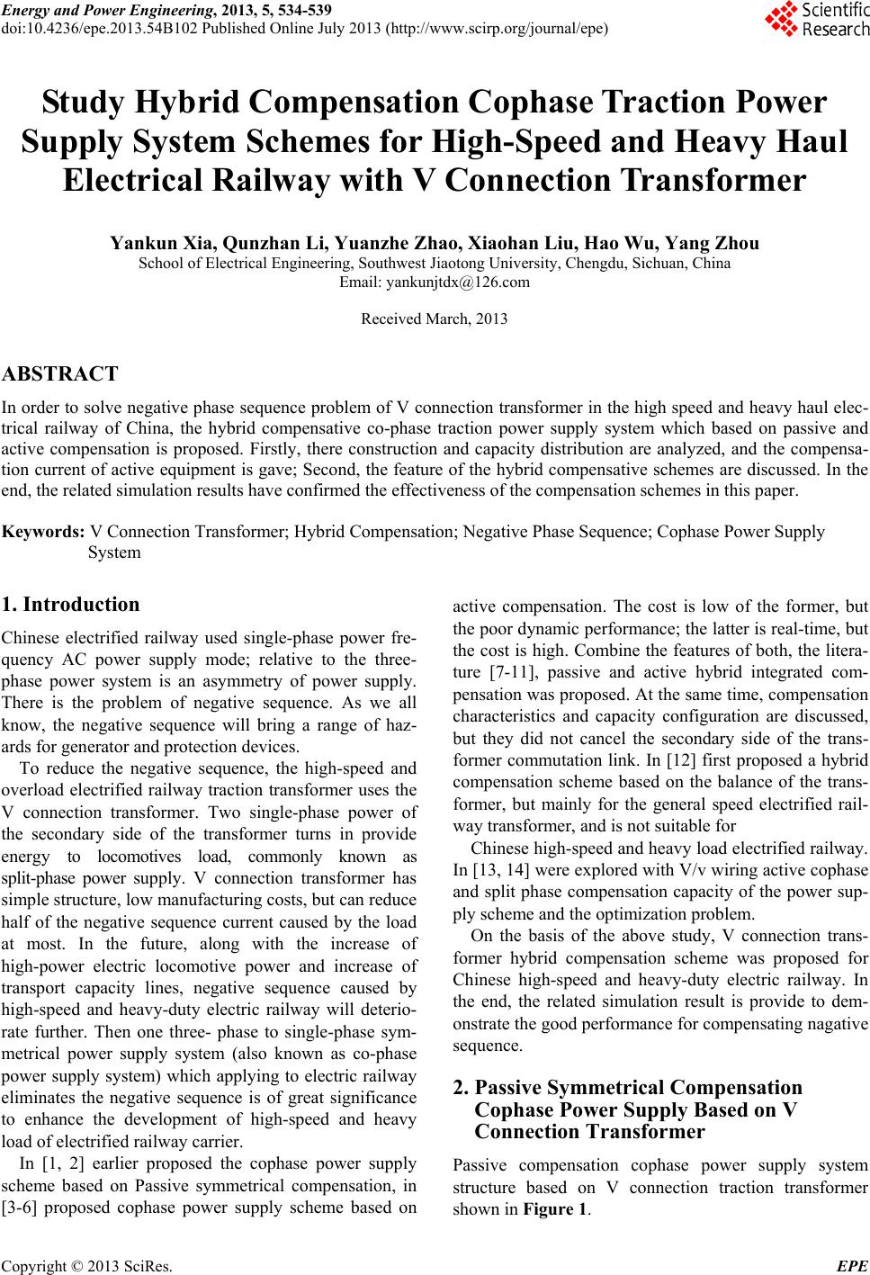 Energy and Power Engineering, 2013, 5, 534-539 doi:10.4236/epe.2013.54B102 Published Online July 2013 (http://www.scirp.org/journal/epe) Study Hybrid Compensation Cophase Tr action Power Supply System Schemes for High-Speed and Heavy Haul Electrical Railway with V Connection Transformer Yankun Xia, Qunzhan Li, Yuanzhe Zhao, Xiaohan Liu, Hao Wu, Yang Zhou School of Electrical Engineering, Southwest Jiaotong University, Chengdu, Sichuan, China Email: yankunjtdx@126.com Received March, 2013 ABSTRACT In order to solve negative phase sequence problem of V connection transformer in the high speed and heavy haul elec- trical railway of China, the hybrid compensative co-phase traction power supply system which based on passive and active compensation is proposed. Firstly, there construction and capacity distribution are analyzed, and the compensa- tion current of active equipment is gave; Second, the feature of the hybrid compensative schemes are discussed. In the end, the related simulation results have confirmed the effectiveness of the compensation schemes in this paper. Keywords: V Connection Transformer; Hybrid Compensation; Negative Phase Sequence; Cophase Power Supply System 1. Introduction Chinese electrified railway used single-phase power fre- quency AC power supply mode; relative to the three- phase power system is an asymmetry of power supply. There is the problem of negative sequence. As we all know, the negative sequence will bring a range of haz- ards for generator and protection devices. To reduce the negative sequence, the high-speed and overload electrified railway traction transformer uses the V connection transformer. Two single-phase power of the secondary side of the transformer turns in provide energy to locomotives load, commonly known as split-phase power supply. V connection transformer has simple structure, low manufacturing costs, but can reduce half of the negative sequence current caused by the load at most. In the future, along with the increase of high-power electric locomotive power and increase of transport capacity lines, negative sequence caused by high-speed and heavy-duty electric railway will deterio- rate further. Then one three- phase to single-phase sym- metrical power supply system (also known as co-phase power supply system) which applying to electric railway eliminates the negative sequence is of great significance to enhance the development of high-speed and heavy load of electrified railway carrier. In [1, 2] earlier proposed the cophase power supply scheme based on Passive symmetrical compensation, in [3-6] proposed cophase power supply scheme based on active compensation. The cost is low of the former, but the poor dynamic performance; the latter is real-time, but the cost is high. Combine the features of both, the litera- ture [7-11], passive and active hybrid integrated com- pensation was proposed. At the same time, compensation characteristics and capacity configuration are discussed, but they did not cancel the secondary side of the trans- former commutation link. In [12] first proposed a hybrid compensation scheme based on the balance of the trans- former, but mainly for the general speed electrified rail- way transformer, and is not suitable for Chinese high-speed and heavy load electrified railway. In [13, 14] were explored with V/v wiring active cophase and split phase compensation capacity of the power sup- ply scheme and the optimization problem. On the basis of the above study, V connection trans- former hybrid compensation scheme was proposed for Chinese high-speed and heavy-duty electric railway. In the end, the related simulation result is provide to dem- onstrate the good performance for compensating nagative sequence. 2. Passive Symmetrical Compensation Cophase Power Supply Based on V Connection Transformer Passive compensation cophase power supply system structure based on V connection traction transformer shown in Figure 1. Copyright © 2013 SciRes. EPE 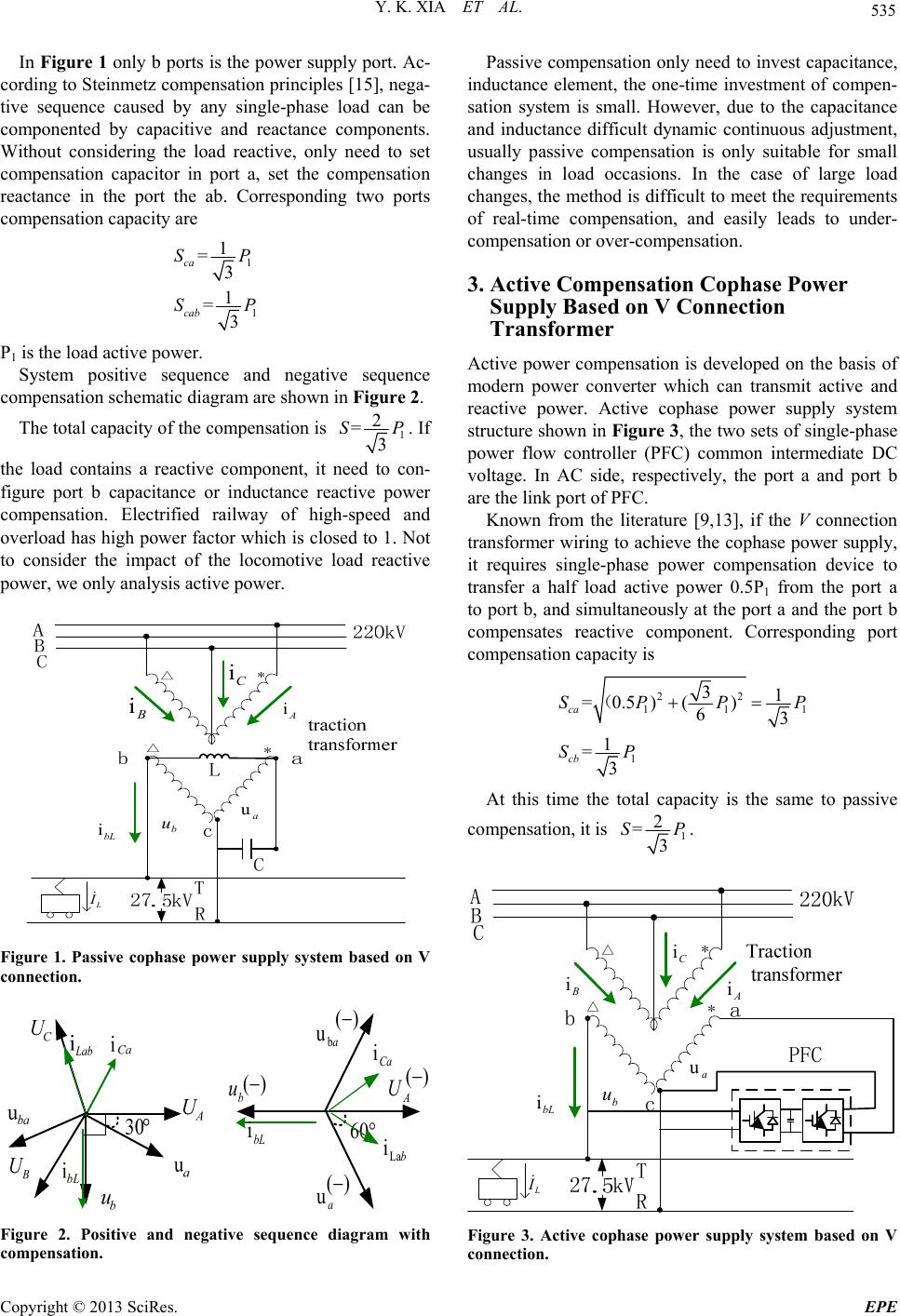 Y. K. XIA ET AL. 535 In Figure 1 only b ports is the power supply por t. Ac- cording to Steinmetz compensation principles [15], nega- tive sequence caused by any single-phase load can be componented by capacitive and reactance components. Without considering the load reactive, only need to set compensation capacitor in port a, set the compensation reactance in the port the ab. Corresponding two ports compensation capacity are 1 1 1 =3 1 =3 ca cab SP SP P1 is the load active power. System positive sequence and negative sequence compensation schematic diagram are shown in Figure 2. The total capacity of the compensation is 1 2 =3 SP . If the load contains a reactive component, it need to con- figure port b capacitance or inductance reactive power compensation. Electrified railway of high-speed and overload has high power factor which is closed to 1. Not to consider the impact of the locomotive load reactive power, we only analysis active power. bL i L I a u b u A i C i B i Figure 1. Passive cophase power supply system based on V connection. () A U b u a u bL i 60 () () bLa i Ca i ab u () Figure 2. Positive and negative sequence diagram with compensation. Passive compensation only need to invest capacitance, inductance element, the one-time investment of compen- sation system is small. However, due to the capacitance and inductance difficult dynamic continuous adjustment, usually passive compensation is only suitable for small changes in load occasions. In the case of large load changes, the method is difficult to meet the requirements of real-time compensation, and easily leads to under- compensat ion or over- compens ation. 3. Active Compensation Cophase Power Supply Based on V Connection Transformer Active power compensation is developed on the basis of modern power converter which can transmit active and reactive power. Active cophase power supply system structure shown in Figure 3, the two sets of single-phase power flow controller (PFC) common intermediate DC voltage. In AC side, respectively, the port a and port b are the link port of PFC. Known from the literature [9,13], if the V connection transformer wiring to achieve the cophase power supply, it requires single-phase power compensation device to transfer a half load active power 0.5P1 from the port a to port b, and simultaneously at the port a and the port b compensates reactive component. Corresponding port compensation capacity is 22 11 1 31 =0.5)() 63 1 =3 ca cb SPP SP (1 P At this time the total capacity is the same to passive compensation, it is 1 2 =3 SP . bL i L I a u b u A i B i C i Figure 3. Active cophase power supply system based on V connection. Copyright © 2013 SciRes. EPE 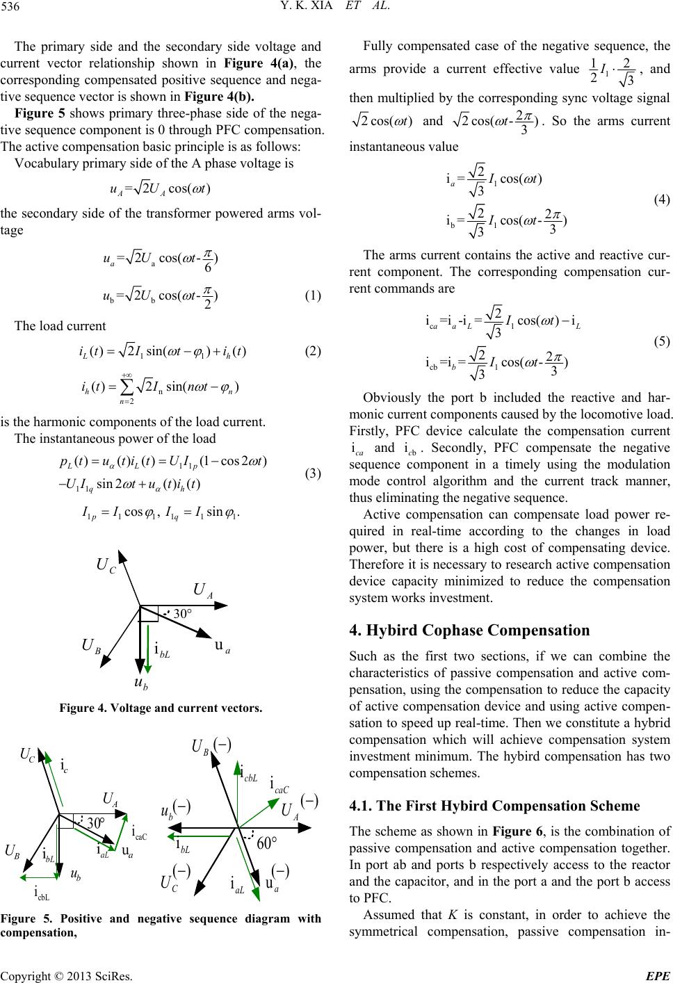 Y. K. XIA ET AL. 536 The primary side and the secondary side voltage and current vector relationship shown in Figure 4(a), the corresponding compensated positive sequence and nega- tive sequence vector is shown in Figure 4(b). Figure 5 shows primary three-phase side of the nega- tive sequence component is 0 through PFC compensation. The active compensation basic principle is as follows: Vocabulary primary side of the A phase voltage is =2cos( ) AA uU t the secondary side of the transformer powered arms vol- tage a =2cos(- ) 6 a uU t bb =2cos(- ) 2 uU t (1) The load current 11 ()2 sin()() Lh it I tit (2) n 2 ()2 sin() h n itInt n is the harmonic components of the load current. The instantaneous power of the load 11 11 ()() ()(1cos2) sin2() () LLp qh ptutit UIt UItuti t (3) 11 111 cos, sin. pq IIII 1 A U B U C U b u a u 30 bL i Figure 4. Voltage and current vectors. cbL i caC i () A U B U C U b u a u bL i aL i 60 () ()() () cbL i caC i Figure 5. Positive and negative sequence diagram with compensation, Fully compensated case of the negative sequence, the arms provide a current effective value 1 12 23 I , and then multiplied by the corresponding sync voltage signal 2cos( )t and 2 2cos( -) 3 t . So the arms current instantaneous value 1 b1 2 i=cos( ) 3 22 i=cos( -) 3 3 aIt It (4) The arms current contains the active and reactive cur- rent component. The corresponding compensation cur- rent commands are c1 cb 1 2 i=i-i=cos()i 3 22 i=i=cos( -) 3 3 aaL L b It It (5) Obviously the port b included the reactive and har- monic current components caused by the locomotive load. Firstly, PFC device calculate the compensation current and ica b ic. Secondly, PFC compensate the negative sequence component in a timely using the modulation mode control algorithm and the current track manner, thus eliminating the negative sequence. Active compensation can compensate load power re- quired in real-time according to the changes in load power, but there is a high cost of compensating device. Therefore it is necessary to research active compensation device capacity minimized to reduce the compensation system works investment. 4. Hybird Cophase Compensation Such as the first two sections, if we can combine the characteristics of passive compensation and active com- pensation, using the compensation to reduce the capacity of active compensation device and using active compen- sation to speed up real-time. Then we constitute a hybrid compensation which will achieve compensation system investment minimum. The hybird compensation has two compensation schemes. 4.1. The First Hybird Compensation Scheme The scheme as shown in Figure 6, is the combination of passive compensation and active compensation together. In port ab and ports b respectively access to the reactor and the capacitor, and in the port a and the port b access to PFC. Assumed that K is constant, in order to achieve the symmetrical compensation, passive compensation in- Copyright © 2013 SciRes. EPE  Y. K. XIA ET AL. 537 vestment capacity is S1, and active device input capacity is S2 11 21 2 =k 3 2 =(1) 3 SP SkP k[0,1] Obviously the scheme inputs a major change capacity weight of passive and active compensation, does not change the total capacity of the whole co mpensation sys- tem inputs 4.2. The Second Hybird Compensation Scheme Inspired by the active compensation, the second hybrid compensation scheme is shown in Figure 7. The passive compensation device and active compensation device connecte to the port a and port b. PFC device transfers half active power of load. Passive compensates reactive component in two ports. Under the conditions of fully compensated, passive compensation invested capacity S1 and active device input capacity S2 bL i L I a u b u A i B i C i Figure 6. The first mode of hybird cophase power supply system. bL i L I a u b u A i B i C i Figure 7. The second mode of hybird co phase power supply system. The passive and active compensation capacity ratio is fixed in this scheme, the total input capacity will reach 1.577P1. PFC compensation current in two port are 1 1 2 b2 i=2sin( -30) i=-2sin( -90) I ca I c t t 4.3. Hybrid Compensation Characteristics 1) By the preceding sections that the total capacity of purely passive compensation and the pure active com- pensation device are equal 1 2 =3. In the first hybrid compensation, the total capacity remain SP 1 2 =3, but the scheme two will result in a significant increase in total capacity. Obviously from saving the entire system capacity point of view, the first sch eme is better than the second. SP 2) Two hybrid options, the power factor of the three- phase system is not affected, because the capacity of the passive capacitive and reactance is equal. 3) Due to the high speed and heavy load electric lo- comotives with regenerative function, when the locomo- tive in the regeneration conditions, locomotive current flow traction transformer. At this condition, negative sequence produced by locomotives and passive devices compensation is superimposed, resulting in deterioration of the negative sequence. Then it need greater active compensation device to compensate. In order to reduce the capacity requirements of the active devices, passive compensating means should as far as possible through the switching switch out of operation in the regenerative brake of the locomotive, and then the active device ca- pacity demand remains 1 2 =3 SP . 5. Simulation Analysis In order to validate the correctness of the principle of hybird cophase compensation schemes, simulation in Matlab/simulink platform is done. Side of power system voltage is 220 kV. Traction network rated voltage is 27.5 kV. The PFC device uses a single-phase back-to- back structure. The step-down transformer voltage ratio is 27500:930. The intermediate DC side voltage of PFC is set to 3000 V. Control system uses voltage and current double closed-loop structure. Locomotive load is consid- ered as constant power source. Figure 8 shows in the port b locomotive load active power is 10 MW. Taken passive compensation degree k = 0.5, the current imbalance is 50% when only a passive compensation, the capacitance and reactance capacity are the 2.887 MVA; then implementation of the active com- pensation, two-port active capacity are 2.887 MVA in a-phase and b-phase port. The basic balance of the three-phase side current imbalance is 0. Compensation device total input capacity is 11.548 MVA. Copyright © 2013 SciRes. EPE 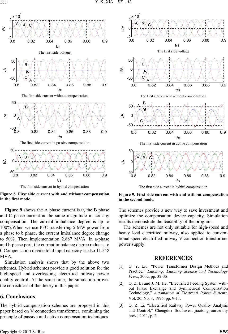 Y. K. XIA ET AL. 538 0.80.82 0.840.86 0.88 0.9 -2 0 2x 10 5 u/V t/s BC A The first side voltage 0.80.82 0.84 0.86 0.880.9 -50 0 50 i/A t/s A B C The first side current without compensation 0.80.82 0.840.86 0.880.9 -50 0 50 i/A t/s A BC The first side current in passive compensation 0.80.82 0.840.86 0.88 0.9 -50 0 50 i/A t/s ABC The first side current in hybird compensation Figure 8. First side current with and without compensation in the first mode. Figure 9 shows the A phase current is 0, the B phase and C phase current at the same magnitude in not any compensation. The current imbalance degree is up to 100%.When we use PFC transferring 5 MW power from a phase to b phase, the current imbalance degree change to 50%. Then implementation 2.887 MVA. In a-phase and b-phase port, the current imbalance degree reduces to 0.Compensation device total input capacity is also 11.548 MVA. Simulation analysis shows that by the above two schemes. Hybrid schemes provid e a good solutio n for the high-speed and overloading electrified railway power quality control. At the same time, the simulation proves the correctness of the theory in this paper. 6. Conclusions The hybrid compensation schemes are proposed in this paper based on V co nnection transformer, combinin g the principle of passive and active compensation techniques. 0.80.82 0.840.86 0.880.9 -2 0 2x 10 5 u/V t/s BC A The first side voltage 0.80.82 0.840.86 0.88 0.9 -50 0 50 i/A t/s A B C The first side current without compensation 0.80.82 0.840.86 0.880.9 -50 0 50 i/A t/s AB C The first side current in active compensation 0.80.820.840.86 0.88 0.9 -50 0 50 i/A t/s ABC The first side current in hybird compensation Figure 9. First side current with and without compensation in the second mode. The schemes provide a new way to save investment and optimize the compensation device capacity. Simulation results demonstrate the feasibility of the program. The schemes are not only suitable for high-speed and heavy load electrified railway, also applied to conven- tional speed electrified railway V connection transformer power supply. REFERENCES [1] C. Y. Liu, “Power Transformer Design Methods and Practice,” Liaoning: Liaoning Science and Technology Press, 2002, pp. 32-35. [2] Q. Z. Li and J. M. He, “Electrified Feeding System with- out Phase Exchange and Symmetrical Compensation Technology,” Automation of Electrical Power Systems, Vol. 20, No. 4, 1996, pp. 9-11. [3] Q. Z. Li, “Electrified Railway Power Quality Analysis and Control,” Chengdu:Southwest jiaotong university press, 2011, p. 2. Copyright © 2013 SciRes. EPE  Y. K. XIA ET AL. Copyright © 2013 SciRes. EPE 539 [4] K. S. Yu and S. J. Zhou, “Electrified Railway Power Sup- ply and Power Quality,” Beijing:China electric power press, 2011, 2. [5] X. F. Zhang, S. B. Gao, Q. Q. Qian, et al., “A Novel Co- phase Traction Power Supply System Based on Imped- ance Matching Balance Transformer and AT Power Sup- ply Mode,” Journal of the China Railway Society, Vol. 8, 2006, pp. 32-37. [6] G. Wei, Q. Z. Li, J. Huang and J. Zhou, “A New Cophase Traction Power Supply System,” Automation of Electrical Power Systems, Vol. 32, No. 10, 2008, pp. 80-83. [7] D. Q. Qiu, Q. Z. Li, F. L. Zhou, et al., “Comprehensive Power Quality Control of Electric Railway Based on Back to Back SVG,” Electric Power Automation Equip- ment, Vol. 30, No. 6, 2010, pp. 36-39. [8] D. Q. Qiu, Q. Z. Li and J. X. Yu, “Compensation Princi- ple of Hybrid Power Quality Conditioner for Electric Railways and Capacity Analysis,” Electric Power Auto- mation Equipment, Vol. 32, No. 10, 2012, pp. 59-64. [9] L. Fang, A. Luo, X. Y. Xu, et al., “A Novel Power Qual- ity Compensator for High-speed Electric Railway,” Transactions of China Electrotechnical Society, Vol. 25, No. 12, 2010, pp. 167-174. [10] C. L. Zeng, A. Luo, F. J. Ma, et al., “A Novel Powerqual- ity Compensation System for High-speed Railway and Its Parameter Design,” Power System Technology, 2011, Vol. 35, No. 10, pp. 64-69. [11] F. J. Ma, A. Luo, X. Y. Xu, et al., “High-power Hybrid Power Quality Compensation System in Electrified Rail- way,” Transactions of China Electrotechnical Sociey, 2011, Vol. 26, No. 10, pp. 93-102. [12] F. L. Zhou, Q. Z. Li and D. Q. Qiu, “Co-phased Traction Power Supply System Based on Hybird Compensation,” Journal of the China Railway Society, 2012, Vol. 34, No. 1, pp. 19-23. [13] G. Wei, “Cophase traction power supply system based on V connection,” Electric Power Automation Equipment, 2010,Vol. 30, No. 12, pp. 60-65. [14] C. P. Wu, A. Luo, et al., “Integrative Compensation Method of Negative Phase Sequence and Harmonic for High-speed Railway Traction Supply System with V/v Transformer,” Proceedings of the CSEE, 2010, Vol. 30, No. 16, pp. 111-117.. [15] Q. Z. Wan, G. P. Zhu, J. Y. Chen, et al., “Optimum De- sign of Compensation Capacity for Balancing the Single Phase Traction Load,” Automation of Electric Power Sys- tems, Vol. 32, No. 8, 2008, pp. 93-97. |