Paper Menu >>
Journal Menu >>
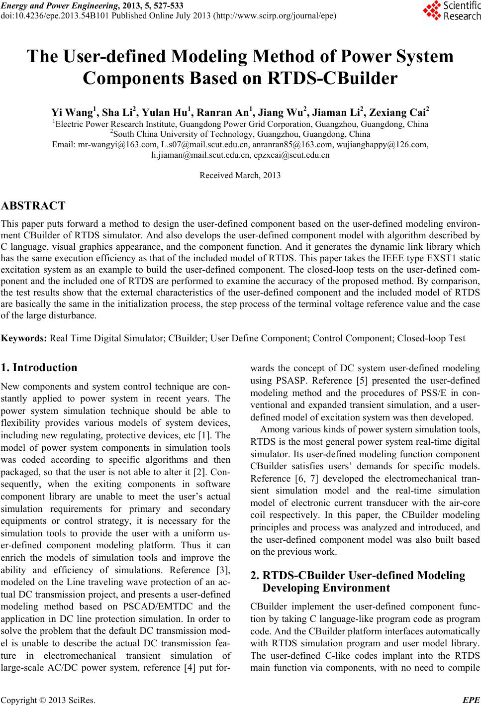 Energy and Power Engineering, 2013, 5, 527-533 doi:10.4236/epe.2013.54B101 Published Online July 2013 (http://www.scirp.org/journal/epe) The User-defined Modeling Method of Power System Components Based on RTDS-CBuilder Yi Wang1, Sha Li2, Yulan Hu1, Ranran An1, Jiang Wu2, Jiaman Li2, Zexiang Cai2 1Electric Power Research Institute, Guangdong Power Grid Corporation, Guangzhou, Guangdong, China 2South China University of Technology, Guangzhou, Guangdong, China Email: mr-wangyi@163.com, L.s07@mail.scut.edu.cn, anranran85@163.com, wujianghappy@126.com, li.jiaman@mail.scut.edu.cn, epzxcai@scut.edu.cn Received March, 2013 ABSTRACT This paper puts forward a method to design the user-defined component based on the user-defined modeling environ- ment CBuilder of RTDS simulator. And also develops the user-defined component model with algorithm described by C language, visual graphics appearance, and the component function. And it generates the dynamic link library which has the same execution efficiency as that of the included model of RTDS. This paper takes the IEEE type EXST1 static excitation system as an example to build the user-defined component. The closed-loop tests on the user-defined com- ponent and the included one of RTDS are performed to examine the accuracy of the proposed method. By comparison, the test results show that the external characteristics of the user-defined component and the included model of RTDS are basically the same in the initialization process, the step process of the terminal voltage reference value and the case of the large disturbance. Keywords: Real Time Digital Simulator; CBuilder; User Define Component; Control Component; Closed-loop Test 1. Introduction New components and system control technique are con- stantly applied to power system in recent years. The power system simulation technique should be able to flexibility provides various models of system devices, including new regulating, protective devices, etc [1]. The model of power system components in simulation tools was coded according to specific algorithms and then packaged, so that the user is not able to alter it [2]. Con- sequently, when the exiting components in software component library are unable to meet the user’s actual simulation requirements for primary and secondary equipments or control strategy, it is necessary for the simulation tools to provide the user with a uniform us- er-defined component modeling platform. Thus it can enrich the models of simulation tools and improve the ability and efficiency of simulations. Reference [3], modeled on the Line traveling wave protection of an ac- tual DC transmission project, and presents a user-defined modeling method based on PSCAD/EMTDC and the application in DC line protection simulation. In order to solve the problem that the default DC transmission mod- el is unable to describe the actual DC transmission fea- ture in electromechanical transient simulation of large-scale AC/DC power system, reference [4] put for- wards the concept of DC system user-defined modeling using PSASP. Reference [5] presented the user-defined modeling method and the procedures of PSS/E in con- ventional and expanded transient simulation, and a user- defined model of excitation system was then developed. Among various kinds of power system simulation tools, RTDS is the most general power system real-time digital simulator. Its user-defined modeling function component CBuilder satisfies users’ demands for specific models. Reference [6, 7] developed the electromechanical tran- sient simulation model and the real-time simulation model of electronic current transducer with the air-core coil respectively. In this paper, the CBuilder modeling principles and process was analyzed and introduced, and the user-defined component model was also built based on the previous work. 2. RTDS-CBuilder User-defined Modeling Developing Environment CBuilder implement the user-defined component func- tion by taking C language-like program code as program code. And the CBuilder platform interfaces automatically with RTDS simulation program and user model library. The user-defined C-like codes implant into the RTDS main function via components, with no need to compile Copyright © 2013 SciRes. EPE 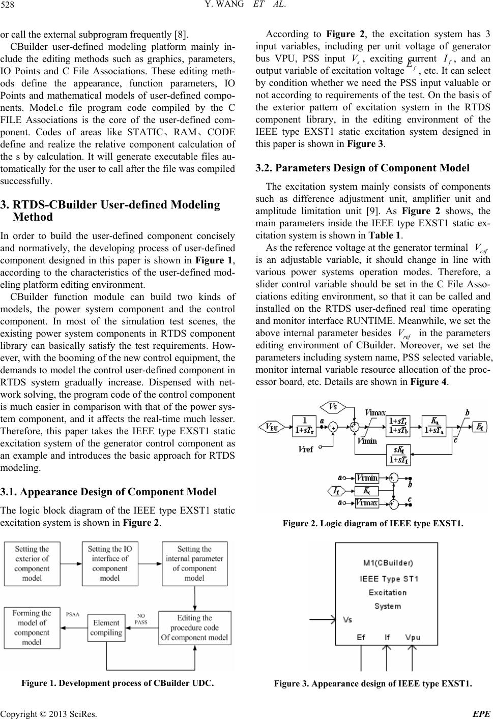 Y. WANG ET AL. 528 or call the external subprogram frequently [8]. CBuilder user-defined modeling platform mainly in- clude the editing methods such as graphics, parameters, IO Points and C File Associations. These editing meth- ods define the appearance, function parameters, IO Points and mathematical models of user-defined compo- nents. Model.c file program code compiled by the C FILE Associations is the core of the user-defined com- ponent. Codes of areas like STATIC、RAM、CODE define and realize the relative component calculation of the s by calculation. It will generate executable files au- tomatically for the user to call after the file was compiled successfully. 3. RTDS-CBuilder User-defined Modeling Method In order to build the user-defined component concisely and normatively, the developing process of user-defined component designed in this paper is shown in Figure 1, according to the characteristics of the user-defined mod- eling platform editing environment. CBuilder function module can build two kinds of models, the power system component and the control component. In most of the simulation test scenes, the existing power system components in RTDS component library can basically satisfy the test requirements. How- ever, with the booming of the new control equipment, the demands to model the control user-defined component in RTDS system gradually increase. Dispensed with net- work solving, the program code of the control component is much easier in comparison with that of the power sys- tem component, and it affects the real-time much lesser. Therefore, this paper takes the IEEE type EXST1 static excitation system of the generator control component as an example and introduces the basic approach for RTDS modeling. 3.1. Appearance Design of Component Model The logic block diagram of the IEEE type EXST1 static excitation system is shown in Figure 2. Figure 1. Development process of CBuilder UDC. According to Figure 2, the excitation system has 3 input variables, including per unit voltage of generator bus VPU, PSS input s V, exciting urrent c f I, and an output variable of excitation voltage f E, etc. It can select by condition whether we need the PSS input valuable or not according to requirements of the test. On the basis of the exterior pattern of excitation system in the RTDS component library, in the editing environment of the IEEE type EXST1 static excitation system designed in this paper is shown in Fi g u r e 3. 3.2. Parameters Design of Component Model The excitation system mainly consists of components such as difference adjustment unit, amplifier unit and amplitude limitation unit [9]. As Figure 2 shows, the main parameters inside the IEEE type EXST1 static ex- citation system is shown in Table 1. As the reference voltage at the generator terminal ref is an adjustable variable, it should change in line with various power systems operation modes. Therefore, a slider control variable should be set in the C File Asso- ciations editing environment, so that it can be called and installed on the RTDS user-defined real time operating and monitor interface RUNTIME. Meanwhile, we set the above internal parameter besides ref in the parameters editing environment of CBuilder. Moreover, we set the parameters including system name, PSS selected variable, monitor internal variable resource allocation of the proc- essor board, etc. Details are shown in Figure 4. V V Figure 2. Logic diagram of IEEE type EXST1. Figure 3. Appearance design of IEEE type EXST1. Copyright © 2013 SciRes. EPE  Y. WANG ET AL. 529 Table 1. Parameters of IEEE type EXST1. Parameter Description f T Time constant of the filter ref V Referenced operating voltage at generator terminal maxi V Maximum voltage inside the system mini V Minimum voltage inside the system a K Gain magnification of the system a T Time constant of the amplifier b T,, c Tf TTime constant of the stable loop f K Gain of the stable loop c K Load factor of commutation reactance rectifier max V Maximum output amplitude limit min V Minimum output amplitude limit Figure 4. Parameter design of IEEE type EXST1. After the above parameters were designed and stored, the parameters will be stored in the C File Associations editing environment of this user-defined component au- tomatically, so that the results can be edited and called by the model.c file and the model.h file. 3.3. Code Design of Component Model As Figure 2 shows, the IEEE type EXST1 static excita- tion system consist of the amplitude limit unit, the trans- fer function of inertial element, the transfer function actual differentiation element, the add and subtract unit, etc. Two types of these transfer functions can be de- scribed as simultaneous of differential equation and al- gebraic equation in their mathematical models. Yet, solu- tion of the differential equation is particularly significant for the execution efficiency of the component program. For the simulation with microsecond calculation step, it can maintain the stability of the value by using explicit solution. In addition, there is no need to solve the equa- tion, so it reduces the amount of calculation [10]. Therefore, this paper takes the inertial element 1/ (1) s T as an example to program it using three explicit solutions. These three solutions for differential equations are shown in Table 2, where R and C are input and output of the equations, T is the time constant, and is the simula- tion step. t In this section, we build the user-defined component model of inertial element 1/(1 ) s T. In the RTDS/Draft file, for the triangular of the included model in RTDS component library and the 3 user-defined component models, which have the input frequency 50 Hz and the amplitude 0.8 pu, we uniformly set the time constant of each component model as 2 s, set the simulation step as 50 μs, and set the relative simulation time as 4 s. We ana- lyze the output data of each model with the simulation time in the vicinity of 4s, as Table 3 shows. We can see from the above table, while the simulation step is set as 50 μs and the simulation time is set as 4 s, the first 4 significant digits of the simulation results from these three algorithms are the same, and the simulation results are relatively close. Comparatively speaking, Table 2. Differential equation’s solution of inertia link. Solutions for differential equations Explicit solution formula EMTDC T t T tetRettCtC 1)()()( Euler T t ttCttRttCtC )]()([)()( Mod-Euler 2/)()()( )]()([)()( )]()([)()( tCtCtCT t tCtRttCtC T t ttCttRttCtC ba ab a Table 3. Simulation results of inertia link. Time (s)RTDS EMTDC Euler Mod-Euler 4.00000 0.346104 0.346104 0.346108 0.346101 3.99975 0.346129 0.346129 0.346133 0.346127 3.99950 0.346152 0.346152 0.346156 0.346150 3.99925 0.346173 0.346173 0.346176 0.346171 3.99900 0.346191 0.346191 0.346194 0.346189 3.99875 0.346206 0.346206 0.346209 0.346205 3.99850 0.346219 0.346219 0.346222 0.346218 3.99825 0.346230 0.346230 0.346232 0.346229 3.99800 0.346238 0.346238 0.346240 0.346237 Copyright © 2013 SciRes. EPE  Y. WANG ET AL. 530 compared with the user-defined component of Mod- Eu- ler and Euler method, the user-defined component using EMTDC algorithm has the simulation results which is closer to that of the transfer function module RTDS comes with. Therefore, in this paper, we solve these 3 types of transfer functions contained in the IEEE type EXST1 static excitation system by using the solutions for differential equations provided by EMTDC. The solution formulas are shown in Table 4 shows, where R and C are input and output of the equation, T is the time constant, and is the simulation step. t Moreover, the programed methods of the amplitude limit unit and add and subtract unit are comparatively easier, and unnecessary details were given here. Accord- ing to the format requirements of model.c file, we edit code in areas such as STATIC, RAM and CODE. As the code in CODE is executed in real time in RTDS, the programming language we wrote should be as efficient as possible [11]. For instance, the parameters which do not need to be re-computed can be computed in RAM area, division should be avoided in CODE area, the vari- able that only be used in CODE area do not need to be declared in STATIC area, etc. Components can right away be called in the RTDS library after compiling. 4. RTDS-CBuilder User-Defined Model Testing Static excitation system model in RTDS has already passed the engineering validation and it meets the appli- cation requirements of engineering facts. By doing com- parison testing using the user-defined model and the RTDS included model, the correctness of the user-de- fined modeling method presented in this paper can be verified. While there are differences between the user- defined component model and the RTDS included model in terms of the choosing of differential equation algo- rithm, the processing modes of each unit, etc [12]. As the source code of the existing component in the component library is unknown, this paper compares in terms of the differences of external performance between the two Table 4. Differential equation’s solution of EMTDC. Transfer function Explicit Solution Formula 1 1ST T t T tetRettCtC1)()()( 1 ST ST T t T t ettRtRettCtC )()()()( 1 2 1 1 ST ST 2 22 )()( 1)()()( 2 1T t T t T t ettRtR T T etRettCtC models. Closed-loop tests were perform to user- defined component model and RTDS included model by setting up specific scenes of the power grid, to examine whether the external characteristics are identical or not. In this paper, we use the power system with the typical connection mode of 500 kV auto transformers in the dy- namic model test standard of the DL/T871-2004 power system relay protection product as the closed-loop test system. The system have 6 nodes by all, including gen- erator MACH1, infinite source SCR1, infinite source SCR2, 500 kV terminal bus BUS1, high voltage side bus of the main transformer BUS2, medium voltage side bus of the main transformer BUS3, low voltage side bus of the main transformer BUS4, 500 kV terminal bus BUS1 and high voltage side bus of the main transformer BUS2 connected via the 200 km single line TL1. The network topological graph of the closed-loop testing system is shown in Figure 5. The typical data of IEEE type EXST1 static excitation system of generator MACH1 is shown in Table 5. Figure 5. Typical wiring of 500 kV autotransformer. Table 5. Typical parameters of IEEE type EXST1. Parameter Value Parameter Value f T 0.0 b T 10.0 ref V 1.01 c T 1.0 maxi V 1.2 f T 1.0 mini V -1.0 f K 0.03 a K 200 max V 5.1 a T 0.4 min V -4.0 c K 0.0 Copyright © 2013 SciRes. EPE  Y. WANG ET AL. 531 The major functions of the excitation system are to provide the excitation source for the generator, stabilize the terminal voltage, demagnetize when the generator shed the load, rapidly and forcibly excite in the case of system disturbances, demagnetize automatically in the case of internal fault of the generator , control the reac- tive power output of the generator, etc [13,14]. Closed- loop tests were then perform to the user-defined compo- nent and the Module in this paper in 3 conditions, in- cluding voltage initialization, the step process of the ter- minal voltage of generator, large system disturbance, etc. The major parameters of the test consist of terminal vol- tage of the generator, excitation voltage f E, the reactive power output of the generator 1 M ACH 1) The voltage initialization process Q, etc. In the process the generator from the end of initializa- tion to the stable state, we need to inspect the establis- ment of excitation voltage, the stabilizing process of the terminal voltage, etc. The recorded experimental data diagram Figure 6 is excitation voltage, Figure 7 is ter- minal voltage, and the recording time is 20s. The gray curves and is the test results to the user-defined component, and the black curves and is the test results to the Module. () f EC () pu VM () pu VC () f EM As Figure 6 and Figure 7 show, the variation trends of these two parameters of the user-defined component and the Module, excitation voltage and terminal voltage, are generally the same. 2) The step process of terminal voltage reference value The terminal voltage reference value was stepped to a certain multiple of the reference value after the system Figure 6. Contrast of excitation voltage in initialization. Figure 7. Contrast of terminal voltage in initialization. entering the stable state. At this moment, examine the rise time and the overshot of the terminal voltage, and the control condition of the reactive power output of the ge- nerator. The recorded experimental data diagram Figure 8 is the excitation voltage, and Figure 9 is the reactive output with the wave recording time 10 s. The gray curves 、1 of these figures are the test results to the user-defined component, and the black curves 、 are the test results to the Module. () f EC ( f EM () MACH QC 1( MACH Q ))M As Figure 8 and Figure 9 show, the variation trend of the two parameters, the excitation voltage and the reac- tive power output, are generally the same. 3) The large system disturbance situation When faults occur to the system, there is a shock to the system voltage, so the voltage stability problem is likely to occur. When faults occur to the AC system in the vi- cinity of the generator, a disturbance is applied to the bus voltage at the generator terminal. As the input of the ex- citation system, the disturbance signal make the excita- tion system adjust dynamically, and stabilize the system voltage. This paper designs the following experimental scenar- ios. After the system entering the stable state, a three-phase fault with the fault duration time 0.1 s was applied to K1 point which was at the main transformer side of line TL1 and then large disturbance occurred in the system. The recorded experimental data diagram Figure 10 is the excitation voltage and Figure 11 is the Figure 8. Contrast of terminal voltage in initialization. Figure 9. Contrast of reactive power in step process. Copyright © 2013 SciRes. EPE  Y. WANG ET AL. 532 Figure 10. Contrast of excitation voltage in large disturbance. Figure 11. Contrast of terminal voltage in large disturbance. terminal voltage, with the recording time 5 s. The gray curves , in these figures are test results to the user-defined component, and the black curves , are test results to the Module. () f EC VC () pu VC ()() f EM pu As Figure 10 and Figure 11 show, the variation trend of these two parameters of the user-defined component and the Module, excitation voltage and terminal voltage, are generally the same. 4) Result analysis of simulation test In this section, external characteristic closed-loop tests were performed to the user-defined component and the Module of the IEEE type EXST1 static excitation system. The variation trends of the user-defined component and the Module parameters, including generator terminal voltage pu , the excitation voltage V f E and the gen- erator reactive power output 1 M ACH , are basically the same, when the system is in the initialization process, the step process of the terminal voltage reference value, the condition of large disturbance, etc. The error should be in an acceptable regime, in the consideration of the difference of selection of transfer function algorithms, the logical unit processing, etc. Therefore, the user- de- fined component of the IEEE type EXST1 static excita- tion system basically meets the test requirements. Q 5. Conclusions This paper introduce the modeling method application of the user-defined modeling module CBuilder using power system real time simulation software RTDS. The model was designed by the user according to the external ap- pearance of power system control component, the input and output and the component parameters. Meanwhile, we edit the internal transfer function and the logic unit using C-like code on the basis of the system logic block diagram. Thus we obtain the user-defined model of the component, and take the IEEE type EXST1 static excita- tion as an example to perform closed-loop simulation verification. The test results indicate that the component model built on the basis of this method, can well imple- ment the controlling function of the component and sat- isfy the users’ simulation demands for the specific model. Meanwhile, the user-defined modeling module possesses fine man-machine interaction interface, and the user- defined component module it built has the advantage of easily-extension, conciseness, efficiency, etc. REFERENCES [1] W. Zhou, “Research on Digital Substation Test System Based RTDS,” Shanghai Jiao Tong University, 2010. [2] Z. Xu and L. J. Qian, “Application Method of RTDS User Define Component Model (UDC),” Power System Pro- tection and Control, Vol. 31, No. 22, 2009, pp. 141-145. [3] Y. H. Liu, Z. X. Cai and A. M. Li, “The User-defined Model of PSCAD/EMTDC and Its Application in Simu- lation of HVDC Transmission Line Protection,” Power System Protection and Control, Vol. 39, No. 9, 2011, pp. 119-124. [4] D. C. Xu, M. X. Han, H. Ding, etc, “Modeling of HVDC Based on the User-defined Model of PSASP,” Automa- tion of Electric Power Systems, Vol. 31, No. 6, 2007, pp. 71-76. [5] Y. X. Chen, X. R. Wang, G. D. Liao, etc, “User Defined Excitation System Models in PSS/E, Power System Tech- nology, Vol. 33, No. 19, 2009, pp. 78-83. [6] H. Y. Bian, H. B. Zhang, R. R. An, etc, “Research and Development of Power System Transient Stability Simu- lation Using Object-oriented Technique,” Automation of Electric Power Systems, Vol. 33, No. 22, 2009, pp. 61-65. [7] W. Zhou, X. T. Li, P. C. Zhang, etc, “Rogowski Real-time Simulation Model of the Electronic Current Transducer Based on Rogowski Coil,” Power System Protection and Control, Vol. 38, No. 19, 2010, pp. 125-129. [8] Z. Wang, “Research of Interfaces Based on Real-time Digital Simulation for Hybrid Real-time Simulation of Electromagnetic-electromechanical Transient Process,” North China Electric Power University, 2010. [9] X. Yang, “User Defined Modeling Method and Its Ap- plication for Excitation System,” Proceedings of the CSU-EPSA, Vol. 23, No. 1, 2011, pp. 69-75. [10] Z. Xu, L. Qian and J. Wang, Basic Method of Building UDC Model for RTDS Simulation, Power and Energy Engineering Conference (APPEEC), 2001, pp. 1-4. Copyright © 2013 SciRes. EPE  Y. WANG ET AL. Copyright © 2013 SciRes. EPE 533 [11] H. Zhang, Research and Implementation of Electrome- chanical Transient Model in the Hybrid Real-time Simu- lation, North China Electric Power University, 2010. [12] T. J. Pu, J. W Qin, L. Dong, etc, “Application of Compo- nent Technology Based User-defined Modeling of Con- trol System in Power System Simulation,” Power System Technology, Vol. 32, No. 24, 2008, pp. 70-75. [13] X. H. Zhao, “The Study of Parameter Identification for Excitation System Based on RTDS,” North China Elec- tric Power University, 2008. [14] Y. Zhang, X. Mao and D. F. Wu, “Exciting System Simu- lation and Pss Sesign by User-Defined Modeling, Power System Technology,” Vol. 22, No. 3, 1998, pp. 14-18. |