Paper Menu >>
Journal Menu >>
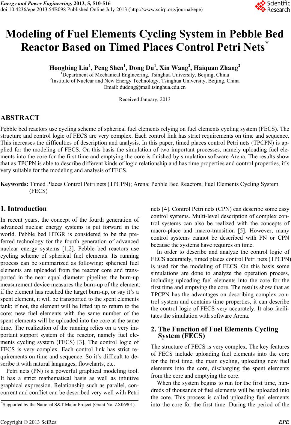 Energy and Power Engineering, 2013, 5, 510-516 doi:10.4236/epe.2013.54B098 Published Online July 2013 (http://www.scirp.org/journal/epe) Modeling of Fuel Elements Cycling System in Pebble Bed Reactor Based on Timed Places Control Petri Nets* Hongbing Liu1, Peng Shen1, Dong Du1, Xin Wang2, Haiquan Zhang2 1Department of Mechanical Engineering, Tsinghua University, Beijing, China 2Institute of Nuclear and New Energy Technology, Tsinghua University, Beijing, China Email: dudong@mail.tsinghua.edu.cn Received January, 2013 ABSTRACT Pebble bed reactors use cycling scheme of spherical fuel elements relying on fuel elements cycling system (FECS). The structure and control logic of FECS are very complex. Each control link has strict requirements on time and sequence. This increases the difficulties of description and analysis. In this paper, timed places control Petri nets (TPCPN) is ap- plied for the modeling of FECS. On this basis the simulation of two important processes, namely uploading fuel ele- ments into the core for the first time and emptying the core is finished by simulation software Arena. The results show that as TPCPN is able to describe different kinds of logic relationship and has time properties and control properties, it’s very suitable for the modeling and analysis of FECS. Keywords: Timed Places Control Petri nets (TPCPN); Arena; Pebble Bed Reactors; Fuel Elements Cycling System (FECS) 1. Introduction In recent years, the concept of the fourth generation of advanced nuclear energy systems is put forward in the world. Pebble bed HTGR is considered to be the pre- ferred technology for the fourth generation of advanced nuclear energy systems [1,2]. Pebble bed reactors use cycling scheme of spherical fuel elements. Its running process can be summarized as following: spherical fuel elements are uploaded from the reactor core and trans- ported in the near equal diameter pipeline; the burn-up measurement device measures the burn-up of the element; if the element has reached the target burn-up, or say it’s a spent element, it will be transported to th e spent elements tank; if not, the element will be lifted up to return to the core; new fuel elements with the same number of the spent elements will be up loaded into the core at the sa me time. The realization of the running relies on a very im- portant support system of the reactor, namely fuel ele- ments cycling system (FECS) [3]. The control logic of FECS is very complex. Each control link has strict re- quirements on time and sequence. So it’s difficult to de- scribe it with natural languages, flowcharts, etc. Petri nets (PN) is a powerful graphical modeling tool. It has a strict mathematical basis as well as intuitive graphical expression. Relationship such as parallel, con- current and conflict can be described very well with Petri nets [4]. Control Petri nets (CPN) can describe some easy control systems. Multi-level description of complex con- trol systems can also be realized with the concepts of macro-place and macro-transition [5]. However, many control systems cannot be described with PN or CPN because the systems have requires on time. In order to describe and analyze the control logic of FECS accurately, timed places control Petri nets (TPCPN) is used for the modeling of FECS. On this basis some simulations are done to analyze the operation process, including uploading fuel elements into the core for the first time and emptying the core. The results show that as TPCPN has the advantages on describing complex con- trol system and contains time properties, it can describe the control logic of FECS very accurately. It also facili- tates the simulation with software Arena. 2. The Function of Fuel Elements Cycling System (FECS) The structure of FECS is very complex. The key features of FECS include uploading fuel elements into the core for the first time, the main cycling, uploading new fuel elements into the core, discharging the spent elements from the core and emptying the core. When the system begins to run for the first time, hun- dreds of thousan ds of fuel elements will be u ploaded into the core. This process is called uploading fuel elements into the core for the first time. During the period of the *Supported by the Nation a l S&T Major Project (Grant No. ZX06901). Copyright © 2013 SciRes. EPE 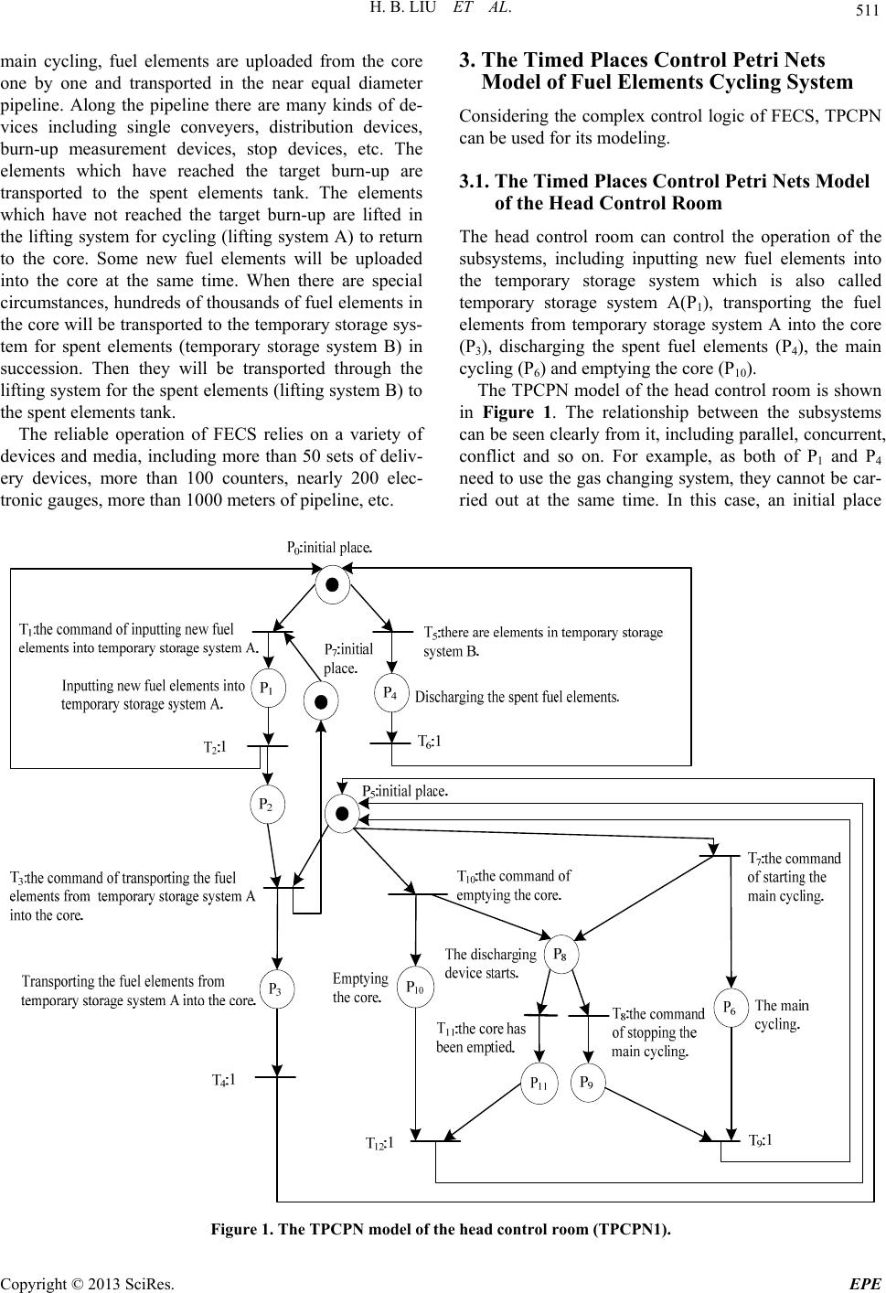 H. B. LIU ET AL. 511 main cycling, fuel elements are uploaded from the core one by one and transported in the near equal diameter pipeline. Along the pipeline there are many kinds of de- vices including single conveyers, distribution devices, burn-up measurement devices, stop devices, etc. The elements which have reached the target burn-up are transported to the spent elements tank. The elements which have not reached the target burn-up are lifted in the lifting system for cycling (lifting system A) to return to the core. Some new fuel elements will be uploaded into the core at the same time. When there are special circumstances, hundreds of thousands of fuel elements in the core will be transported to the temporary stor age sys- tem for spent elements (temporary storage system B) in succession. Then they will be transported through the lifting system for the spent ele ments (lifting system B) to the spent elements tank. The reliable operation of FECS relies on a variety of devices and media, including more than 50 sets of deliv- ery devices, more than 100 counters, nearly 200 elec- tronic gauges, more than 1000 meters of pipeline, etc. 3. The Timed Places Control Petri Nets Model of Fuel Elements Cycling System Considering the complex control logic of FECS, TPCPN can be used for its modeling. 3.1. The Timed Places Control Petri Nets Model of the Head Control Room The head control room can control the operation of the subsystems, including inputting new fuel elements into the temporary storage system which is also called temporary storage system A(P1), transporting the fuel elements from temporary storage system A into the core (P3), discharging the spent fuel elements (P4), the main cycling (P6) and emptying the core (P10). The TPCPN model of the head control room is shown in Figure 1. The relationship between the subsystems can be seen clearly from it, including parallel, concurrent, conflict and so on. For example, as both of P1 and P4 need to use the gas changing system, they cannot be car- ried out at the same time. In this case, an initial place Figure 1. The TPCPN model of the head control room (TPCPN1). Copyright © 2013 SciRes. EPE 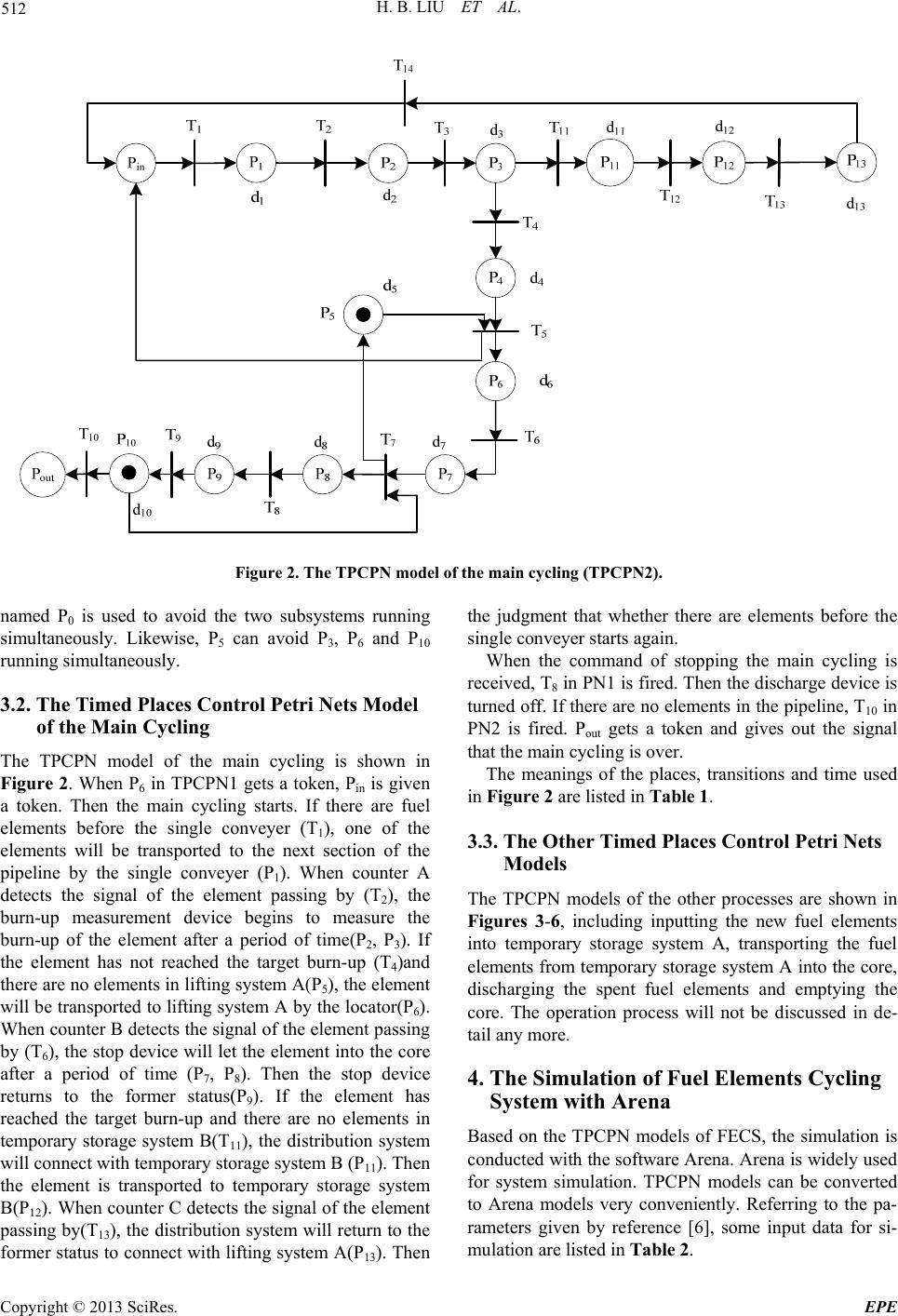 H. B. LIU ET AL. 512 Figure 2. The TPCPN model of the main cycling (TPCPN2). named P0 is used to avoid the two subsystems running simultaneously. Likewise, P5 can avoid P3, P6 and P10 running simultaneously. 3.2. The Timed Places Control Petri Nets Model of the Main Cycling The TPCPN model of the main cycling is shown in Figure 2. When P6 in TPCPN1 gets a token, Pin is given a token. Then the main cycling starts. If there are fuel elements before the single conveyer (T1), one of the elements will be transported to the next section of the pipeline by the single conveyer (P1). When counter A detects the signal of the element passing by (T2), the burn-up measurement device begins to measure the burn-up of the element after a period of time(P2, P3). If the element has not reached the target burn-up (T4)and there are no elements in lifting system A(P5), the element will be transported to liftin g system A by the locator(P6). When counter B detects the signal of the element passing by (T6), the stop device will let the element into the co re after a period of time (P7, P8). Then the stop device returns to the former status(P9). If the element has reached the target burn-up and there are no elements in temporary storage system B(T11), the distribution system will connect with temporary storage system B (P11). Then the element is transported to temporary storage system B(P12). When counter C detects the signal of the element passing by(T13), the distribution system will return to the former status to connect with lifting system A(P13). Then the judgment that whether there are elements before the single conveyer starts again. When the command of stopping the main cycling is received, T8 in PN1 is fired. Then the discharge device is turned off. If there are no elements in the pipeline, T10 in PN2 is fired. Pout gets a token and gives out the signal that the main cycling is over. The meanings of the places, transitions and time used in Figure 2 are listed in Table 1. 3.3. The Other Timed Places Control Petri Nets Models The TPCPN models of the other processes are shown in Figures 3-6, including inputting the new fuel elements into temporary storage system A, transporting the fuel elements from temporary storage system A into the core, discharging the spent fuel elements and emptying the core. The operation process will not be discussed in de- tail any more. 4. The Simulation of Fuel Elements Cycling System with Arena Based on the TPCPN models of FECS, the simulation is conducted with the software Arena. Arena is widely used for system simulation. TPCPN models can be converted to Arena models very conveniently. Referring to the pa- rameters given by reference [6], some input data for si- mulation are listed in Table 2. Copyright © 2013 SciRes. EPE 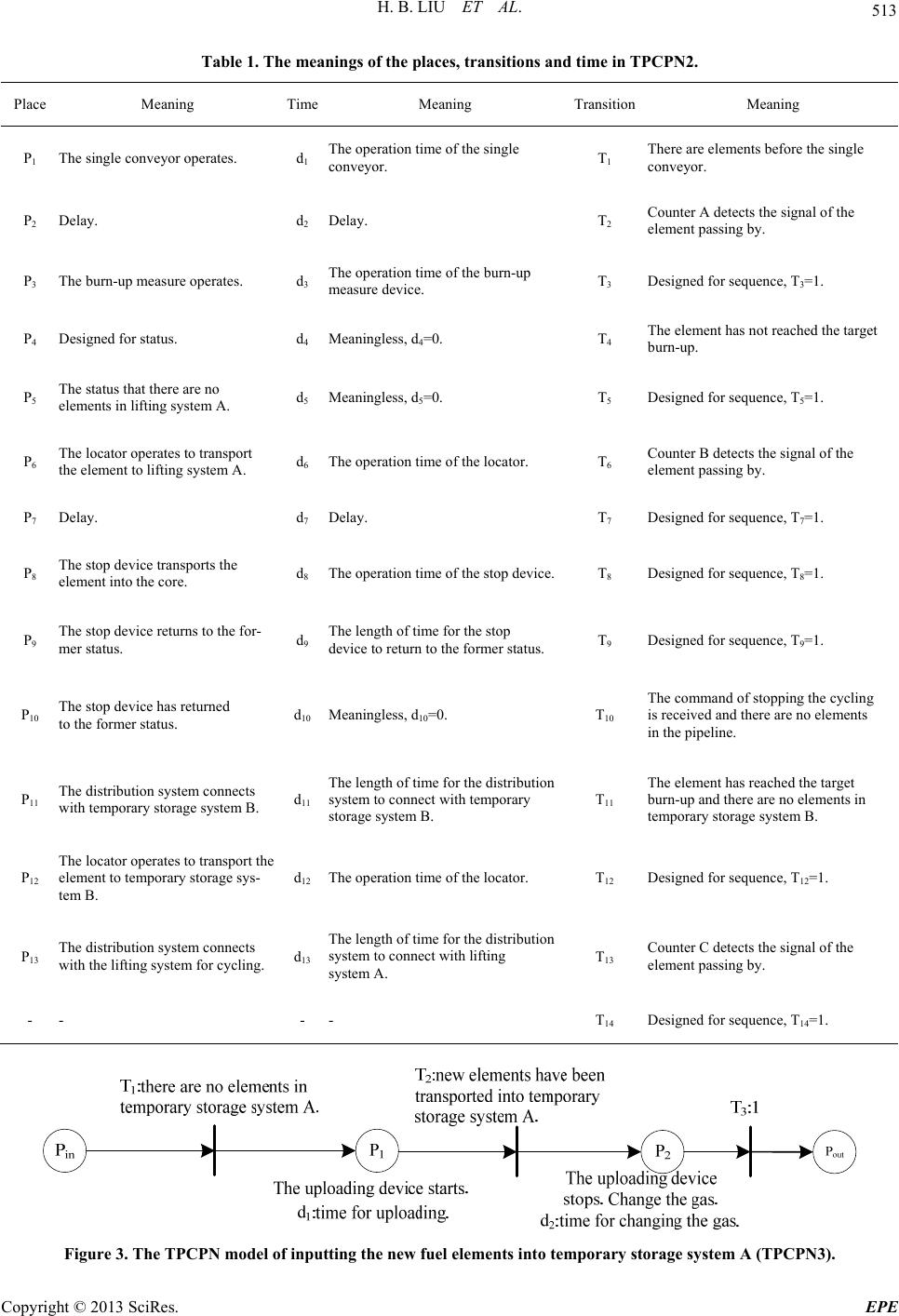 H. B. LIU ET AL. 513 Table 1. The meanings of the places, transitions and time in TPCPN2. Place Meaning Time Meaning TransitionMeaning P1 The single conveyor operates. d1 The operation time of the single conveyor. T1 There are elements before the single conveyor. P2 Delay. d2 Delay. T2 Counter A detects the signal of the element passing by. P3 The burn-up measure operates. d3 The operation time of the burn-up measure device. T3 Designed for sequence, T3=1. P4 Designed for status. d4 Meaningless, d4=0. T4 The element has not reached the target burn-up. P5 The status that there are no elements in lifting system A. d5 Meaningless, d5=0. T5 Designed for sequence, T5=1. P6 The locator operates to transport the element to lifting system A. d6 The operation time of the locator. T6 Counter B detects the signal of the element passing by. P7 Delay. d7 Delay. T7 Designed for sequence, T7=1. P8 The stop device transports the element into the core. d8 The operation time of the stop device.T8 Designed for sequence, T8=1. P9 The stop device returns to the for- mer status. d9 The length of time for the stop device to return to the former status. T9 Designed for sequence, T9=1. P10 The stop device has returned to the former status. d10 Meaningless, d10=0. T10 The command of stopping the cycling is received and there are no elements in the pipeline. P11 The distribu tion system connects with temporary storage system B. d11 The length of time for the distribution system to connect with temporary storage system B. T11 The element has reached the target burn-up and there are no elements in temporary storage system B. P12 The locator operates to transport the element to temporary storage sys- tem B. d12 The operation time of the locator. T12 Designed for sequence, T12=1. P13 The distribution system connects with the lifting system for cycling. d13 The length of time for the distribution system to connect with lifting system A. T13 Counter C detects the signal of the element passing by. - - - - T14 Designed for sequence, T14=1. Figure 3. The TPCPN mode l of inputting the new fuel elements into temporary storage system A (TPCPN3). Copyright © 2013 SciRes. EPE  H. B. LIU ET AL. 514 Figure 4. The TPCPN model of transporting the fuel elements from temporary storage system A into the core (TPCPN4). Figure 5. The TPCPN model of discharging the spent fuel elements (TPCPN5). Figure 6. The TPCPN model of emptying the core (TPCPN6). Table 2. Some input data for simulation. Data Unit Value The design capacity of temporary storage sys- tem A. - 100 The length of time for the fuel element lifting in lifting system A. s 9.6 The length of time for the fuel element lifting in lifting system B. s 3.0 The operation time of the delivery device. s 1.0 4.1. The Simulation of Uploading Fuel Elements into the Core for the First Time with Arena During this stage, 6 thousand to 12 thousand fuel elements will be uploaded into the core. The pro cesses of inputting the new fuel elements into temporary storage system A and transporting the fuel elements from temporary storage system A into the core will be carried out. The gas needn’t be changed. Considering the capacity of temporary storage system A, a group of 100 fuel elements will be put into tempo- rary storage system A at regular intervals. Then the ele- Copyright © 2013 SciRes. EPE  H. B. LIU ET AL. 515 ments will be lifted in lifting system A and transported into the core. The simulation result shows that if the time period be and shorten th fuel elements into th able 3 that as the nu able 3. The relationship between the number of elements the number of the minimum time the time it costs tween each two groups is 9 min, the utilization rate of lifting system A is 80.07% while the utilization rate of temporary storage system A is as high as 92.22%. In this case, it will take 14.70 hours to transport 10 thousand fuel elements into the core. If the task is 12 thousand elements, the time cost is 17.65 hours. The utilization rate of temporary storage system A is so high that the speed o f uploading fuel elements is li mited. In order to improve the speed of uploading e consuming time, a method called grouped tandem pneumatic lifting (GTPL) given by reference [7] can be used for the lifting process of the fuel elements. This method can realize several elements lifted together. The process of lifting is steady. Thus the lifting and trans- porting efficiency is much higher. The task is to upload 10 thousand e core. If the maximum utilization rate of lifting system A is limited to below 90%, the relationship between the number of elements lifted together and the time it costs to finish the task is listed in Table 3. A conclusion can be got from T mber of elements lifted together increases, there is a marked decrease in the minimum time between each two groups. The time required to finish the task is reduced. T lifted together and the time it costs to finish the task. elements lifted together period between each two groups (min) to finish the task (h) 1 9.3 15.50 2 5.3 8.83 3 4.0 6.67 4 3.4 5.67 5 2.9 4.83 Thn bfueo the fta pleteorter tim he core is simulated. The result s - celle speed of emptying the core is limited by aximum speed of be emptied in a shorter time. quirements on TPCPN has time properties and con- an describe the control logic accu- orld Development of Nu- Temperature Gas-cooled Reactor,” Chinese Journal of Nuclear Science and Engi- neering, 2000( gdes.2009.02.023 able 4. The simulation result of emptying the core with mber of the maximum number of the time it costs T GTPL. the nu elements lifted together uploading elements from the core (min-1) to empty the core (day) 1 9.6 43.40 2 17.6 23.67 3 24.5 17.01 4 30.0 13.89 5 35.3 11.80 6 40.0 10.42 e method ca e core for th d in a sh e used for uploading irst time so that the e. l elements int sk can be com- 4.2. The Simulation of Emptying the Core with Arena The process of emptying t shows that the process of lifting the spent elements ha been the bottleneck as the burn-up measurement is can d. So the the process of lifting the spen t elements. In order to meet the requirements of the speed, the method of GTPL is used. The simulation result is shown in Table 4. It can be seen from Table 4 that the m uploading elements from the core increases as the number of elements lifted together increases. In this way the core can 5. Conclusions FECS of pebble bed reactors has very complex control logic. Every control link has very strict ac time and sequence. trol properties. It c rately. So it’s very suitable for the modeling of FECS. In addition the simulation of FECS can be conducted to analyze the control logic. This provides the basis for the design opt i mizati o n of react o r s. REFERENCES [1] Z. X. Wu and Z. Y. Zhang, “W clear Power System and High 3), pp. 211-219. [2] Z. Y. Zhang, Z. X. Wu, D. Z. Wang, et al., “Current Status and Technical Description of Chinese 2×250 MWth HTR-PM Demonstration Plant,” Nuclear Engi- neering and Design, Vol. 239, No. 7, 2009, pp. 1212-1219. doi:10.1016/j.nucen [3] P. Shen, D. Du, G. L. Guo, et al., “Research on Pneu- matic Transportation of Fuel Elements in Pebble Bed Re- actor,” Power and Energy Engineering Conference (AP- PEEC), Shanghai, China, 2012. [4] T. Murata, “Petri Nets - Properties, Analysis and Appli- cations,” Proceedings of the IEEE, Vol. 77, No. 4, 1989, pp. 541-580. doi:10.1109/5.24143 [5] Z. D. Han, J. G. Liu and S. Luo Sheng, “Design Method of Control System for HTGR Fuel Handling Process with Control Petri Net,” Nuclear Power Engineering, Vol. 29, No. 1, 2008, pp. 14-18. [6] P. Shen, K. Zeng, Du Dong, et al., “Dynamic Modeling and Application of Pneumatic Near-diameter Spheres in Pipeline Transportation in A Pebble Bed Reactor,” Qinghua Daxue Xuebao, Vol. 52, No. 8, 2012, pp. Copyright © 2013 SciRes. EPE  H. B. LIU ET AL. Copyright © 2013 SciRes. EPE 516 ed Reactor,” CHN Patent No. 1075-1080. [7] P. Shen, D. Du, H. B. Liu, et al., “A Method of Grouped Tandem Fuel Elements of Pneumatic Transportation in Pebble B CN201210227180.8, 2012. |