Energy and Power Engineering, 2013, 5, 505-509
doi:10.4236/epe.2013.54B097 Published Online July 2013 (http://www.scirp.org/journal/epe)
Passive Cooldown Performance of Integral Pressurized
Water Reactor
Shoubao Dai, Chunnan Jin, Jingfu Wang, Yuxiang Chen
NO.703 Research Institute of China Shipbuilding Industry Corporation, Harbin, China
Email: daishoubao@126.com
Received January, 2013
ABSTRACT
The design of an integral pressurized water reactor (IPWR) focuses on enhancing the safety and reliability of the reactor
by incorporating a number of inherent safety features and engineered safety features. However, the characteristics of
passive safety systems for the marine reactors are quiet different from those for the land nuclear power plant because of
the more formidable and dangerous operation environments of them. This paper presents results of marine black out
accident analyses. In the case of a transient, the passive residual heat removal system (PRHRS) is designed to cool the
reactor coolant system (RCS) from a normal operation condition to a hot shutdown condition by a natural circulation,
and the shutdown cooling syste m (SCS) is designed to cool the primary system from a hot shutdown condition to a re-
fueling condition by a forced circulation. A realistic calculation has been carried out by using the RELAP5/MOD3.4
code and a sensitivity analysis has been performed to evaluate a passive cooldown capability. The results of the accident
analyses show that the reactor coolant system and the passive residual heat removal system adequately remove the core
decay heat by a natural circulation.
Keywords: An Integral Pressurized Water Reactor (IPWR); Passive Safety System; Styling; Natural Circulation
1. Introduction
Most of the primary circuit components of an integral
pressurized water reactor (IPWR) are housed within a
single reactor pressure vessel (RPV). This layout can
provide the optimum configuration for adopting inherent
and passive safety design. So they are suitable for the
medium/small size nuclear power plants and marine nu-
clear systems. However, the characteristics of passive
safety systems for the marine reactors are quiet different
from those for the land nuclear power plant because of
the more formidable and dangerous run environments of
them. Consequently, in orde r to ensure the reliability and
the security of the marine-used IPWR, it is of great im-
portance to perform detailed investigation on the opera-
tion characteristics of their passive safety systems [1,2].
The IPWR with 100 MW capab ility is designed in this
paper. Fundamental concept and general arrangement of
the IPWR in this paper is based on the same principle of
the Inherent Safe UZrHx Power Reactor [3] and the Rus-
sian ABV-6M IPWR [4]. This 100 MW integral reactor
adopts the arc plate fuels in core, casing once-through
steam generator (OTSG), inherent safety improving fea-
tures such as a large volume of the reactor coolant, a
large negative moderator temperature coefficient, a low
core power density, and a passive residual heat removal
system (PRHRS). The major design parameters are
summarized in Table 1. The Figure 1 shows a schematic
diagram of the safety systems for the IPWR design.
These safety systems are designed to meet the relevant
redundancy and independency design requirements to
ensure a high reliability and safety.
Table 1. Initial parameters for the system.
System parameters Values Unites
Thermal power 100 MW
Reactor pressure vessel
Operating pressu re
Coolant mass flow
Core inlet temperature
Core outlet temperature
Steam generator
Main steam flow rate
Steam temperature
Feedwater temperature
Steam pressure
Tube outer diameter
Tube inner diameter
Tube length
14
1500
235
286
160
263.84
150
2.943
8×1
10×1.5
1.5
MPa
t/h
t/h
MPa
mm
mm
m
PRHRS
Coolant initial temperature
Coolant initial pressure
Tube inner diameter
Tube length
Water temperature in tank
Water pressure in tank
24
0.1013
16×1.2
1.6
24
0.1013
MPa
mm
m
MPa
Copyright © 2013 SciRes. EPE
S. B. DAI ET AL.
506
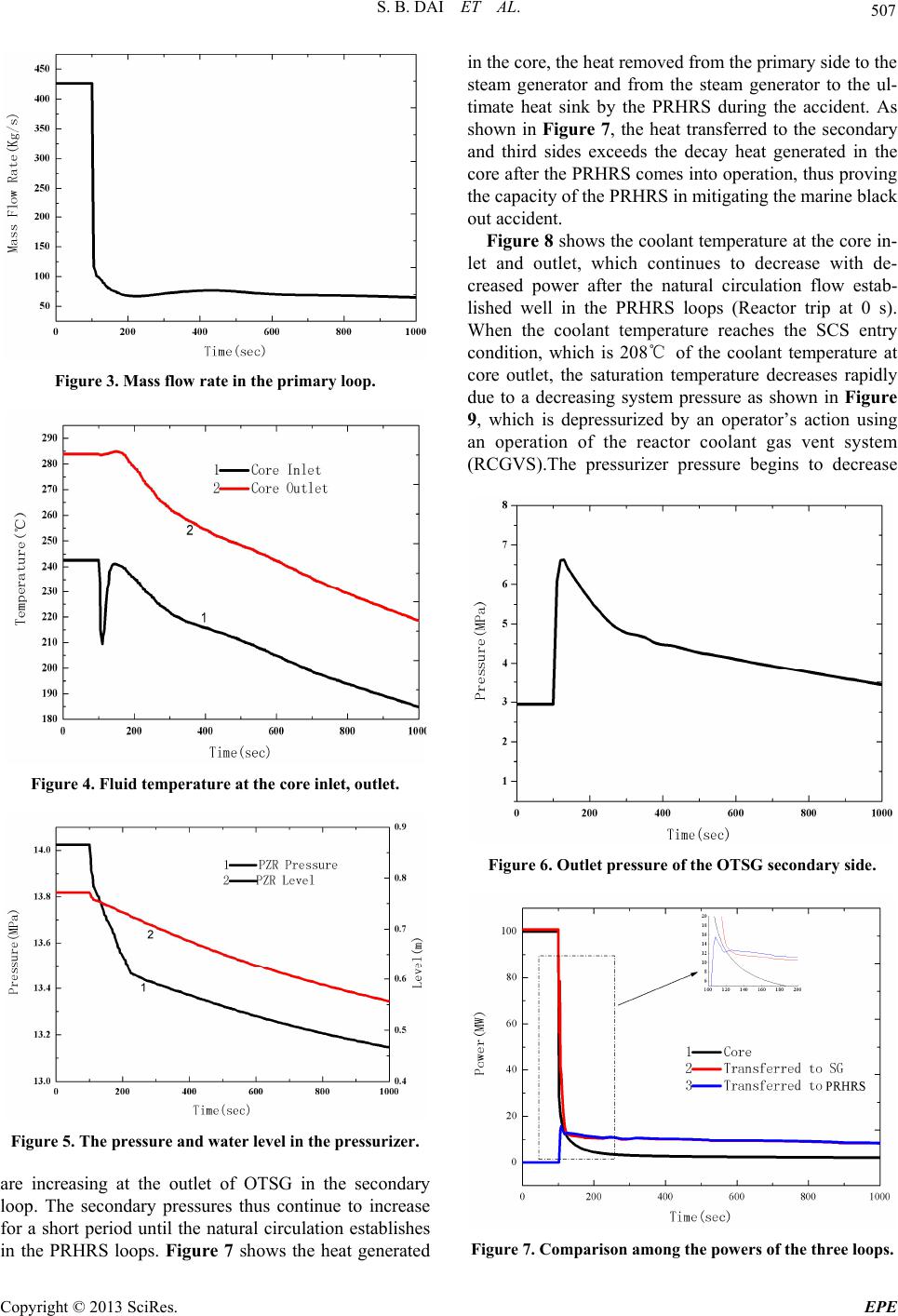
Figure 1. Schematic diagram of the safety system of IPWR.
1.1. Passive Residual Heat Removal System
(PRHRS)
The PRHRS passively removes a core decay heat and a
sensible heat by a natural circulation in case of an emer-
gency condition such as unavailability of feed-water
supply or marine black out. Besides, the PRHRS may
also be used in case of long-term cooling for repair [5 ].
The IPWR can cool down the primary coolant from a
normal operation to a hot shutdown using a passive safe-
ty system when the reactor is tripped while a loop-type
commercial PWR cools down the co olant using an activ e
system such as an auxiliary feed-water system. The ac-
tive system can maintain a co ns tant coo ldown rate for the
transient, however, the passive system is relatively diffi-
cult to maintain a constant value because a driving force
reduces when a density difference between a hot and cold
sides is small at the end of transient. Therefore, a cool-
down analysis should be accomplished according to a
well-defined methodology.
1.2. Shutdown Cooling System (SCS)
The shutdown cooling system is designed to remove a
normal heat and a sensible heat in the reactor vessel from
a hot shutdown to a refueling condition. When the reac-
tor coolant system reaches 208 of a coolant tempera-
ture and 2.3 MPa of its pressure, the shutdown cooling
system cools the reactor coolant system to a refueling
condition. The SCS include s a shutdown cooling pump, a
heat exchanger, a water storage tank and valves. The
SCS sucks up a coolant at the main coolant pump (MCP)
suction duct, and then it discharges the coolant to the
main coolant pump discharge region [6].
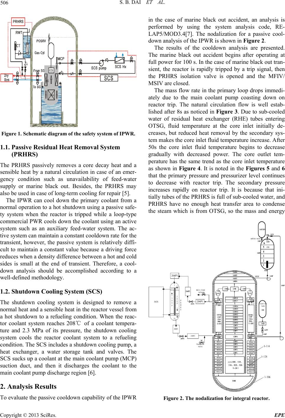
2. Analysis Results
To evaluate the passive cooldo wn cap ability of the IPWR
in the case of marine black out accident, an analysis is
performed by using the system analysis code, RE-
LAP5/MOD3.4[7]. The nodalization for a passive cool-
down analysis of the IPWR is shown in Figure 2.
The results of the cooldown analysis are presented.
The marine black out accident begins after operating at
full power for 100 s. In the case of marine black out tran-
sient, the reactor is rapidly tripped by a trip signal, then
the PRHRS isolation valve is opened and the MFIV/
MSIV are closed .
The mass flow rate in the primary lo op drops immedi-
ately due to the main coolant pump coasting down on
reactor trip. The natural circulation flow is well estab-
lished after 8s as noticed in Figure 3. Due to su b-cooled
water of residual heat exchanger (RHE) tubes entering
OTSG, fluid temperature at the core inlet initially de-
creases, but reduced heat removal by the secondary sys-
tem makes the core inlet fluid temperature increase. After
50s the core inlet fluid temperature begins to decrease
gradually with decreased power. The core outlet tem-
perature has the same trend as the core inlet temperature
as shown in Figure 4. It is noted in the Figures 5 and 6
that the primary pressure and pressurizer level continues
to decrease with reactor trip. The secondary pressure
increases rapidly on reactor trip. It is because that ini-
tially tubes of the PRHRS is full of sub-cooled water, and
PRHRS have no enough heat transfer area to condense
the steam which is from OTSG, so the mass and energy
Figure 2. The nodalization for integral reactor.
Copyright © 2013 SciRes. EPE
S. B. DAI ET AL. 507
Figure 3. Mass flow rate in the primary loop.
Figure 4. Fluid temperature at the core inlet, outlet.
Figure 5. The pressure and water level in the pressurizer.
are increasing at the outlet of OTSG in the secondary
loop. The secondary pressures thus continue to increase
for a short period until the natural circulation establishes
in the PRHRS loops. Figure 7 shows the heat generated
in the core, the heat removed from the primary side to the
steam generator and from the steam generator to the ul-
timate heat sink by the PRHRS during the accident. As
shown in Figure 7, the heat transferred to the secondary
and third sides exceeds the decay heat generated in the
core after the PRHRS comes into operation, thus proving
the capacity of the PRHRS in mitigating the marine black
out accident.
Figure 8 shows the coolant temperature at the core in-
let and outlet, which continues to decrease with de-
creased power after the natural circulation flow estab-
lished well in the PRHRS loops (Reactor trip at 0 s).
When the coolant temperature reaches the SCS entry
condition, which is 208 of the coolant temperature at
core outlet, the saturation temperature decreases rapidly
due to a decreasing system pressure as shown in Figure
9, which is depressurized by an operator’s action using
an operation of the reactor coolant gas vent system
(RCGVS).The pressurizer pressure begins to decrease
Figure 6. Outlet pressure of the OTSG secondary side.
Figure 7. Comparison among the powers of the three loops.
Copyright © 2013 SciRes. EPE
S. B. DAI ET AL.
508
rapidly with the transient and then, it stabilizes at 9MPa.
The system condition needs to be lower than 208 and
2.3 MPa in order to connect the SCS. The reactor coolant
gas vent system is operated to achieve these conditions
when the coolant temperature reaches 208. Then, the
system pressure decreases rapidly again to 2.3 MPa as
shown in Figure 9.
A sensitivity study is performed to establish the cool-
down capability of the 100 MW integral reactor for vari-
ous system conditions such as natural and forced circula-
tion conditions, and the number of PRHRS. The results
are shown in Figure 1 0.
The pn, pf, sn and the sf denote a natural circulation at
the primary system, a forced circulation at the primary
system, a natural circulation at the secondary and a
forced circulation at the secondary system, respectively.
The forced circulation at the primary system is a case
where the main coolant pump is available after a reactor
is tripped and the forced circulation at the secondary
system is a case where 10% of the normal feed-water
flow rate is supplied by a feed-water pump. For the pri-
mary forced circulation condi tion, the coolant temperature
Figure 8. Primary system coolant temperature.
Figure 9. Pressurizer pressure.
Figure 10. Coolant temperature for the sensitivity study.
of the primary system reaches the primary system entry
condition nearly at the same time as the reference calcu-
lation. The cooldown capability of the IPWR is depend
on the primary system condition, that is, a h eat transfer at
the steam generator primary side. Also, the coolant tem-
perature can be cooled to 208 by only one t PRHRS.
However, it takes about 1100 s to reach the SCS entry
condition.
3. Summary and Conclusions
The passive cooldown characteristics and the natural
circulation performance of IPWR with a PRHRS have
been investigated in the case of the marine black out ac-
cident. It is shown that the reactor coolant system and the
PRHRS adequately remove the core decay heat, and as-
sure to remove appropriately a heat capacity in the reac-
tor vessel by natural circulation. For the design bases
accident conditions, IPWR cools down the coolant to the
SCS entry condition within 1100 S for all the possible
boundary conditions. Furthermore, the system can reach
the SCS entry condition by using only one PRHRS. Also,
the safety systems function properly and thus they can
secure the reactor to a safe condition for any accident.
4. Acknowledgements
Dai Shoubao would like to take this chance to express
my sincere gratitude to my supervisor, Jin Chunnan and
Chen Yuxiang, who provide the kindly assistance and
valuable suggestions during the process of this paper.
This gratitud e also extends to the professor Peng Min-
jun who taught him during his undergraduate years for
his kind encouragement and patient instructions.
REFERENCES
[1] Y.-J. Chung, H.-C. Kim and B.-D. Chung, “Two Phase
Natural Circulation and Heat Transfer in the Passive
Copyright © 2013 SciRes. EPE
S. B. DAI ET AL.
Copyright © 2013 SciRes. EPE
509
Residual Heat Removal System of an Integral Type Re-
actor,” Annals of Nuclear Energy, Vol. 33, No. 3, 2006,
pp. 262-270. doi:10.1016/j.anucene.2005.09.009
[2] M. H. Chang, S. K. Sim, D. J. Lee, “SMART Behavior
under Over-Pressurizing Accident Conditions,” Nuclear
Engineering and Design, Vol. 199, No. 1-2, 2000, pp.
187-196. doi:10.1016/S0029-5493(99)00068-0
[3] S. L. Cheng and G. J. Leng, “Inherent Safe UZrHx Power
Reactor INSURE-100 Preliminary Research,” Nuclear
Power Engineering, Vol. 15, No. 4, Aug. 1994.
[4] J. K. Liu and C. B. Tang, “Summarisation on Russian
ABV-6M Integral Pressurized Water Reactor,” Nuclear
Power Engineering, Vol. 18, No. 3,1997.
[5] Y. J. Chung, S. H. Kim and H. C. Kim, “Thermal Hy-
draulic Analysis of SMART for Heat Removal Transients
by a Secondary System,” Nuclear Engineering and De-
sign, 2003, pp. 225-257.
[6] Y.-J. Chung and S. W. Lee, “Passive Cooldown Per-
formance of a 65 MW Integral Reactor,” Nuclear Engi-
neering and Design, Vol. 238, 2008, pp. 1681-1689.
doi:10.1016/j.nucengdes.2007.12.008
[7] C. D. Fletcher and R. R. Schultz. RELAP5/MOD3 Code
Manual Volume V: USER’ S GUIDELINES[Z], 1995,
38-42, 130-133, 139-158, 173-180.