 Modeling and Numerical Simulation of Material Science, 2013, 3, 11-16 doi:10.4236/mnsms.2013.34B003 Published Online October 2013 (http://www.scirp.org/journal/mnsms) Atomistic Simulation of Undissociated 60˚ Basal Dislocation in Wurtzite GaN. I. Belabbas1*, J. Chen2, Ph. Komninou3, G. Nouet4 1Groupe de Cristallographie et de Simulation des Matériaux, Laboratoire de Physico-Chimie des Matériaux et Catalyse. Université Abderrahmane Mira, Bejaïa (06000), Algérie. 2CIMAP, UMR6252 CNRS-CEA-ENSICAEN-Université de Caen Basse-Normandie, 14032, France. 3Department of Physics, Aristotle University of Thessaloniki, GR-54124 Thessaloniki, Greece 4Centre de Recherche sur les Ions, les Matériaux et la Photonique, 6 Boulevard du Maréchal Juin, 14050 Caen cedex, France Email: *imad.belabbas@univ-bejaia.dz Received May, 2013 ABSTRACT We have carried out computer atomistic simulations, based on an efficient density functional based tight binding method, to investigate the core configurations of the 60°basal dislocation in GaN wurtzite. Our energetic calculations, on the undissociated dislocation, demonstrate that the glide configuration with N polarity is the most energetically fa- vorable over both the glide and the shuffle sets. Keywords: Gallium Nitride; 60°Basal Dislocation; Core Structure; Energy; Tight-binding; SCC-DFTB 1. Introduction Wurtzite GaN layers were initially grown along the [0001] direction, also called polar direction [1]. This led to the fabrication of optoelectronic devices, based on heterostructures, which are strongly affected by sponta- neous and piezoelectric polarization effects [2]. These effects are at the origin of the occurrence of a high inter- nal electrostatic field which increases the separation be- tween electrons and holes and thus reducing the overlap of their wavefunctions [2]. The latter causes a strong current dependence of the emission energy and a red shift of optical transitions as well as reduces the emission effi- ciency of optoelectronic devices [2]. The polarization- related effects in wurtzite GaN heterostructures can be completely avoided by adopting growth on alternative orientations. Hence, various growth directions were ex- plored. These were the non-polar directions: , and the semi-polar directions: , and [3]. Then, GaN/AlGaN heterostructures grown along non-polar or semi-polar directions were proven to be free from polarization effects and thus demonstrate a clear improvement of their optical properties with respect to those elaborated along the polar direction. The nature of threading dislocations contained in a wurtzite GaN layer is directly related to the direction of its growth. If the growth direction is [0001], i.e. the polar direction, the threading dislocations are perfect prismatic dislocations, which can be edge, screw or mixed [4]. However, if the growth direction is , i.e. the non-polar direction, the threading dislocations can be perfect or partial basal dislocations [4]. Perfect basal dislocations are screw and 60°-mixed, while partial basal dislocations are Shockley (edge, 30°-mixed), Frank and Frank-Shockley partials [5]. During the last decade, threading prismatic disloca- tions were extensively investigated in gallium nitride, at both experimental and theoretical levels [4]. For these dislocations, models for their core structures were pro- posed and their impact on the electronic properties of GaN was nearly elucidated [6-8]. The body of work dedicated to basal dislocations in GaN still insufficient compared to that to prismatic dislocations [4], while among basal dislocations, partials [9] were more investi- gated regarding the perfect ones [10,11]. The perfect screw dislocation was investigated atomistically and the energetic hierarchy of its core configurations was estab- lished by Belabbas et al. [12]. The perfect 60° dislocation was studied in cubic GaN by Blumenau et al. [13] but unfortunately no theoretical report exists for the wurtzite phase. At the experimental level, the perfect 60 °dislocation was observed by using electron micros- copy. By combining conventional transmission electron microscopy and cathodoluminescence measurements, Albrecht et al. [14] investigated the 60°dislocation in wurtzite GaN and analyzed its electronic and optical ac- *Corresponding author. Copyright © 2013 SciRes. MNSMS  I. BELABBAS ET AL. 12 tivities. They found it to be likely responsible for a para- sitic luminescence around 2.9 eV. However, due the lim- ited resolution of their used microscope, the previous authors were not able to establish if this observed behav- ior is that of a full or a dissociated dislocation. In a sub- sequent study, Niermann et al. [15] have observed a dis- sociated 60°dislocation by using high resolution trans- mission electron microscopy. The separation between the two resulting Shockley partials was found to be smaller than 2 nm. In the present contribution, we have carried out com- puter atomistic simulations to investigate the core con- figurations of the 60°basal dislocation in GaN wurtzite. 2. Models and Simulation Details The 60°basal dislocation has a mixed character (edge and screw). In the wurtzite crystal structure, this dislocation is perfect and has its line along the direction and its Burgers vector is which has a magnitude equal to a (a = 3.18Ǻ stands for the basal lattice vector of GaN). The 60°basal dislocation may have several core configurations, which depends on the position of its centre. If the latter is located between two narrowly spaced {0001} planes, called the glide set, the dislocation will have a glide configuration. However, if the centre of the dislocation is situated between two widely spaced {0001} planes, called the shuffle set, the dislocation will have a shuffle configuration. As gallium nitride is a compound semiconductor, a glide (or a shuffle) core configuration may exists in two different polarities: gallium or nitrogen. This depends on the nature of the ending atom at the additional half plane, which is at the origin of the edge component of the dislocation. The 60°basal dislocation was modeled atomistically by using the so-called supercell-cluster hybrid model [6-8]. The atoms at the model’s lateral surface (Ga/N) have to be saturated by fractionally charged (1.25e/0.75e) pseudo-hydrogen atoms which allow getting rid of dan- gling bonds and their associated unwanted gap states [6-8]. The supercell-cluster hybrids were at least dou- bled along direction in order to take into account any possible reconstruction along the dislocation line. The size of the models considered here is ranging from 750 to 1000 atoms and their lateral extension is typically about 26Ǻ. Although the lateral extension of the model is finite, periodic boundary conditions were applied later- ally to the dislocation line while including a 50Ǻ of vac- uum. The equilibrium atomic positions were obtained through a minimization procedure based on the conjugate gradient algorithm where energies and forces are evalu- ated by using the SCC-DFTB method [16]. During this step all the atoms, including those at the model’s lateral surfaces, were allowed to relax freely. The equilibrium is reached when the maximum force acting on each atom of the system is well below 0.0001a.u. 3. Results and Discussion For the 60°basal dislocation, we have considered four core configurations: a shuffle configuration with nitro- gen polarity (60°-SN), a shuffle configuration with gal- lium polarity (60°-SGa), a glide configuration with a gallium polarity (60°-GGa) and a glide configuration with nitrogen polarity (60°-GN). These core configura- tions are represented respectively in figures (1.a, 1.b, 1.c, 1.d). In the following we will present and discuss our results concerning the atomic description of the previous core configurations and their energetics. 3.1. Atomic Core Structure The 60°-SN core configuration (Figure 1(a)) presents a structure with an asymmetric 8-atoms ring. This is different from the 8-atoms ring structure exhibited by the prismatic edge dislocation which processes mirror plane symmetry [17]. All the atoms forming the core are fully coordinated except those of the column (1) which involves dangling bonds (Figure 1(a)). The most compressed bonds (-8.21%) are established between the atoms of columns (1) and (8), while the most stretched bonds (+13.33%) are established between the atoms of columns (5) and (6). The chemical bonds involved in the core present an angular dispersion ranging from 93°to 128 °. The 60°-SGa core configuration (Figure 1(b)) has, as in the previous one, a structure with an asymmetric 8- atoms ring. However, while the 60°-SN configuration exhibits a single period structure, a complex reconstruc- tion takes place in the 60°-SGa configuration, leading to doubling its period along the dislocation line. This re- construction consists in establishing alternated Ga-Ga bonds (2.81 Ǻ) between the atoms of columns (1) and (5), while occurring in column (6) dangling bonds within a 2a period. In this core configuration, the most com- pressed Ga-N bonds (-7.18%) are involved by the low coordinated atoms of column (1) and those of column (8). The most stretched Ga-N bonds (+17.44%) are estab- lished between the atoms of columns (5) and (6). The most extreme bond angles (79°and 154°) are recorded for the atoms of column (5). The 60°-GGa core configuration (Figure 1(c)) exhibits a structure with an asymmetric 5/7-atoms ring. This core configuration includes only Ga-Ga bonds separating the 5-atoms and 7-atoms rings, which make it different from the symmetric core configuration of a prismatic edge dislocation where both Ga-Ga and N-N are separating the two atomic rings [17]. In the configuration 60°-GGa, the Ga-Ga bonds (2.32 Ǻ) are established between the atoms of columns (3) and (9). The Copyright © 2013 SciRes. MNSMS  I. BELABBAS ET AL. Copyright © 2013 SciRes. MNSMS 13 latter contains under- coordinated Ga atoms. The most compressed Ga-N bonds (-5.64%) are involved between the (3) and (9) atomic columns, while the most stretched bonds (+10.77%) are established between the atoms of columns (5) and (6) and those of columns (6) and (7). The most extreme bond angles (90°and 138°) are recorded for the atoms of column (3). The 60°-GN core configuration (Figure 1(d)) has a structure with an asymmetric 5/7-atoms ring, which con- tains some N-N bonds. The considerable difference in bond lengths between the N-N bonds (1.58 Ǻ), involved in this configuration, and the Ga-Ga bonds, involved in the previous configuration, makes the 60°-GN core con- figuration less spatially extended than the 60°-GGa core configuration. In the configuration 60°-GN, the column (9) does contain under-coordinated N atoms. The most com- pressed Ga-N bonds (-6.67%) are established between the atoms of columns (8) and (9). The most stretched bonds (+7.18%) are involved by, in one hand, the atoms of columns (2) and (3) and, in the other hand, by the at- oms of columns (5) and (6). The bond angles present a dispersion ranging from 92° to 134°. 3.2. Energetics The energetic hierarchy of the four core configurations of the 60°basal dislocation was accessed through a com- bination of continuum elasticity theory and atomistic calculations based on the SCC-DFTB method. The total strain energy (total ) associated with a dislocation can be represented as a sum of elastic () and core () contributions: E elastic Ecore E totalelastic core EE E (1) within linear elasticity, the elastic strain energy per unit length stored in a cylinder of radius R around the disloca- tion is given by the relation [18]: (d) 1 2 3 4 5 6 7 8 9 10 (a) 1 2 3 4 5 6 7 8 (b) 1 2 3 4 5 6 7 8 (c) 1 2 3 4 5 6 7 8 9 1 Figure 1. Ball and stick models for relaxed core configurations of the mixed 60° basal dislocation, projected along the [1120] direction. Black balls represent gallium atoms and the white ones nitrogen atoms. (a): View of the 60°-SN core configuration. (b): View of the 60°-SGa core configuration. (c): View of the 60°-GGa core configuration. (d): View of the 60°-GN core configu- ration.  I. BELABBAS ET AL. 14 (/) for elastic cc EAlnRR RR 2 (2) where Rc is the dislocation core radius. For a mixed type dislocation, the pre-logarithmic factor is related to both the edge and screw components of the Burgers vector of the dislocation (be and bs respectively) and it is given, within anisotropic elasticity, by the relation [18]: 2 (1 /4) () eess KbK b (3) In the case of a mixed basal dislocation, the energy factors e and , associated respectively with the edge and the screw components, are given by the rela- tions [18]: 1/2 4411 3313 11 3313 3311 331344 () () (2 e CCCC KCCC CCCC C ) (4a) and 44 66s CC (4b) where are the elastic constants of the material. ij Within the SCC-DFTB method, one can define the ex- cess energy of a single atom as its difference in energy in the system with presence of the defect and that in bulk material. Hence, the total strain energy (total ) contained in a cylinder of radius R around the dislocation is evalu- ated by summing the excess of energy related to individ- ual atoms belonging to this area. In order to determine the core parameters of the dislocation, i.e. core energy and core radius, we plotted the total strain energy (total ) versus ln(R), for the four considered core configurations (Figure 2). These curves exhibit three distinct domains: a central linear region bordered by two non-linear ones. The linear region represents the so-called elastic region while the non-linear region close to the centre of the dis- location represents the so-called core region. The ap- pearance of a quick enhancement of the strain energy, in the second non-linear region, is attributed to surface ef- fects. C E E Fitting the linear parts of the strain energy curves with equation (2) allowed us to determine the values of the pre-logarithmic factor (Afit) which represents the slope of these curves. The obtained values are ranging from -1.3% to -10.4% (Table 1) with respect to theoretical value of A = 0.77eV/Ǻ, evaluated by using equation (3) and the experimental values of the elastic constants. The core radius of a particular core configuration is defined as the value of the radius from which the strain energy curve cesses of being linear, when going to the centre of the dislocation. The core energy is defined as the value of the energy corresponding to the core radius [7]. The obtained core energies and radii of the four core configurations of the 60°basal dislocation are summa- rized in Table 1. Then, the comparison of the core ener- gies, evaluated at a common radius of 6Å, shows that within the glide set, the configuration with a nitrogen core (60°-GN) is energetically favorable over the con- figuration with a gallium core (60°-GGa). However, the opposite is observed in the shuffle set, where the con- figuration with a gallium core (60°-SGa) has lower core energy than the configuration with a nitrogen core (60° -SN). The core configuration 60°-GN was found to be the most energetically favorable over both the glide and the shuffle sets. Otherwise, our calculations show that the core energy difference of the glide configurations (0.53 eV/Å) is higher than that of the shuffle ones (0.11eV/Å). Core region Elastic region Figure 2. The total strain energy per unit length stored in a cylinder of radius R as a function of ln(R) for different core con- figurations of the 60° basal dislocation: 60°-SN, 60-SGa, 60°-GN and 60°-GGa. Copyright © 2013 SciRes. MNSMS 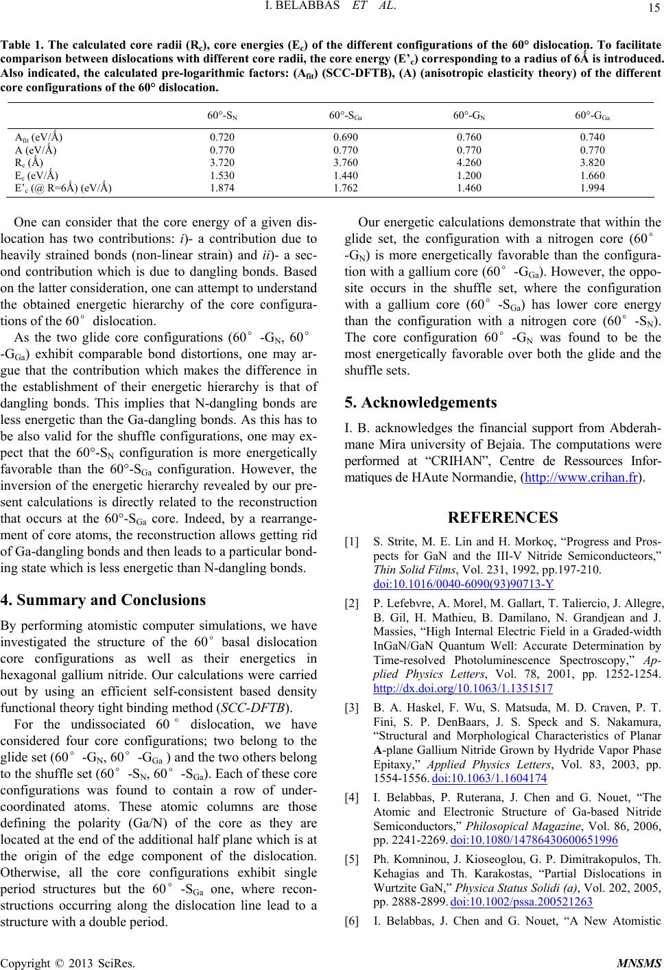 I. BELABBAS ET AL. 15 Table 1. The calculated core radii (Rc), core energies (Ec) of the different configurations of the 60° dislocation. To facilitate comparison between dislocations with different core radii, the core energy (E’c) corresponding to a radius of 6Ǻ is introduced. Also indicated, the calculated pre-logarithmic factors: (Afit) (SCC-DFTB), (A) (anisotropic elasticity theory) of the different core configurations of the 60° dislocation. 60°-SN 60°-SGa 60°-GN 60°-GGa Afit (eV/Ǻ) A (eV/Ǻ) Rc (Ǻ) Ec (eV/Ǻ) E’c (@ R=6Ǻ) (eV/Ǻ) 0.720 0.770 3.720 1.530 1.874 0.690 0.770 3.760 1.440 1.762 0.760 0.770 4.260 1.200 1.460 0.740 0.770 3.820 1.660 1.994 One can consider that the core energy of a given dis- location has two contributions: i)- a contribution due to heavily strained bonds (non-linear strain) and ii)- a sec- ond contribution which is due to dangling bonds. Based on the latter consideration, one can attempt to understand the obtained energetic hierarchy of the core configura- tions of the 60°dislocation. As the two glide core configurations (60°-GN, 60° -GGa) exhibit comparable bond distortions, one may ar- gue that the contribution which makes the difference in the establishment of their energetic hierarchy is that of dangling bonds. This implies that N-dangling bonds are less energetic than the Ga-dangling bonds. As this has to be also valid for the shuffle configurations, one may ex- pect that the 60°-SN configuration is more energetically favorable than the 60°-SGa configuration. However, the inversion of the energetic hierarchy revealed by our pre- sent calculations is directly related to the reconstruction that occurs at the 60°-SGa core. Indeed, by a rearrange- ment of core atoms, the reconstruction allows getting rid of Ga-dangling bonds and then leads to a particular bond- ing state which is less energetic than N-dangling bonds. 4. Summary and Conclusions By performing atomistic computer simulations, we have investigated the structure of the 60°basal dislocation core configurations as well as their energetics in hexagonal gallium nitride. Our calculations were carried out by using an efficient self-consistent based density functional theory tight binding method (SCC-DFTB). For the undissociated 60°dislocation, we have considered four core configurations; two belong to the glide set (60°-GN, 60°-GGa ) and the two others belong to the shuffle set (60°-S N, 60°-SGa). Each of these core configurations was found to contain a row of under- coordinated atoms. These atomic columns are those defining the polarity (Ga/N) of the core as they are located at the end of the additional half plane which is at the origin of the edge component of the dislocation. Otherwise, all the core configurations exhibit single period structures but the 60°-SGa one, where recon- structions occurring along the dislocation line lead to a structure with a double period. Our energetic calculations demonstrate that within the glide set, the configuration with a nitrogen core (60° -GN) is more energetically favorable than the configura- tion with a gallium core (60°-GGa). However, the oppo- site occurs in the shuffle set, where the configuration with a gallium core (60°-SGa) has lower core energy than the configuration with a nitrogen core (60°-SN). The core configuration 60°-GN was found to be the most energetically favorable over both the glide and the shuffle sets. 5. Acknowledgements I. B. acknowledges the financial support from Abderah- mane Mira university of Bejaia. The computations were performed at “CRIHAN”, Centre de Ressources Infor- matiques de HAute Normandie, (http://www.crihan.fr). REFERENCES [1] S. Strite, M. E. Lin and H. Morkoç, “Progress and Pros- pects for GaN and the III-V Nitride Semiconducteors,” Thin Solid Films, Vol. 231, 1992, pp.197-210. doi:10.1016/0040-6090(93)90713-Y [2] P. Lefebvre, A. Morel, M. Gallart, T. Taliercio, J. Allegre, B. Gil, H. Mathieu, B. Damilano, N. Grandjean and J. Massies, “High Internal Electric Field in a Graded-width InGaN/GaN Quantum Well: Accurate Determination by Time-resolved Photoluminescence Spectroscopy,” Ap- plied Physics Letters, Vol. 78, 2001, pp. 1252-1254. http://dx.doi.org/10.1063/1.1351517 [3] B. A. Haskel, F. Wu, S. Matsuda, M. D. Craven, P. T. Fini, S. P. DenBaars, J. S. Speck and S. Nakamura, “Structural and Morphological Characteristics of Planar A-plane Gallium Nitride Grown by Hydride Vapor Phase Epitaxy,” Applied Physics Letters, Vol. 83, 2003, pp. 1554-1556. doi:10.1063/1.1604174 [4] I. Belabbas, P. Ruterana, J. Chen and G. Nouet, “The Atomic and Electronic Structure of Ga-based Nitride Semiconductors,” Philosopical Magazine, Vol. 86, 2006, pp. 2241-2269. doi:10.1080/14786430600651996 [5] Ph. Komninou, J. Kioseoglou, G. P. Dimitrakopulos, Th. Kehagias and Th. Karakostas, “Partial Dislocations in Wurtzite GaN,” Physi ca St atus Soli di (a), Vol. 202, 2005, pp. 2888-2899. doi:10.1002/pssa.200521263 [6] I. Belabbas, J. Chen and G. Nouet, “A New Atomistic Copyright © 2013 SciRes. MNSMS  I. BELABBAS ET AL. 16 Model for the Threading Screw Dislocation Core in Wurtzite GaN,” Computational Materials Science, Vol. 51, 2011, pp. 206-216. doi:10.1016/j.commatsci.2011.07.051 [7] I. Belabbas, A. Béré, J. Chen, S. Petit, M. A. Belkhir, P. Ruterana and G. Nouet, “Atomistic Modeling of the (a+c)-Mixed Dislocation Core in Wurtzite GaN,” Physi- cal Review B, Vol. 75, 2007, pp. 115201-115211. doi:10.1103/PhysRevB.75.115201 [8] I. Belabbas, M. A. Belkhir, Y. H. Lee, A. Béré, P. Ruter- ana, J. Chen and G. Nouet, “Local Electronic Structure of Threading Screw Dislocation in GaN Wurtzite,” Compu- tational Materials Science, Vol. 37, 2006, pp. 410-416. doi:10.1016/j.commatsci.2005.11.002 [9] I. Belabbas, G. P. Dimitrakopulos, J. Kioseoglou, A. Béré, J. Chen, Ph. Komninou, P. Ruterana and G. Nouet, “En- ergetics of the 30° Shockley Partial Dislocation in Wurtz- ite GaN,” Superlattices and Microstructures, Vol. 40, 2006, pp. 458-463. doi:10.1016/j.spmi.2006.09.013 [10] I. Belabbas, J. Chen, M. A. Belkhir, P. Ruterana and G. Nouet, “New Core Configurations of the C-edge Disloca- tion in Wurtzite GaN,” Physica Status Solidi (c), Vol. 3, 2006, pp. 1733-1737. [11] I. Belabbas, J. Chen, M. A. Belkhir, P. Ruterana and G. Nouet, “Ab-initio Tight-binding Study of the Core of the Core Structures of the C-edge Dislocation in Wurtzite GaN,” Physica Status Solidi (a), Vol. 203, 2006, pp. 2167-2171. doi:10.1002/pssa.200566003 [12] I. Belabbas, G. Nouet and Ph. Komninou, “Atomic Core Configurations of the A-screw Basal Dislocation in wurtzite GaN,” Journal of Crystal Growth, Vol. 300, 2007, pp. 212-216. doi:10.1016/j.jcrysgro.2006.11.022 [13] A. T. Blumenau, J. Elsner, R. Jones, M. I. Heggie, S. Oberg, Th. Frauenheim and PR. Briddon, “Dislocations in Hexagonal and Cubic GaN,” Journal of Physics: Con- densed Matter, Vol. 12, 2000, pp. 10223-10233. doi:10.1088/0953-8984/12/49/322 [14] M. Albrecht, H. P. Strunk, J. L. Weyher, I. Grzegory, S. Porowski and T. Wosinski, “Carrier Recomnination at Single Dislocation in GaN Measured by Cathodolumi- nescence in a Transmission Electron Microscope,” Jour- nal of Applied Physics, Vol. 92, 2002, pp. 2000-2005. doi:10.1063/1.1490618 [15] T. Niermann, M. Kocan, M. Roever, D. Mai, J. Malin- dretos, A. Rizzi and M. Seibt, “High Resolution Imaging of Extended Defects in GaN Using Wave Function Re- construction,” Physica Status Solidi (a), Vol. 4, 2007, pp. 3010-3014. doi:10.1002/pssc.200675451 [16] M. Elstner, D. Porezag, G. Jungnickel, J. Elsner, M. Haugk, Th. Frauenheim, S. Suhai and G. Seifert, “Self-consistent-charge density-functional tight-binding method for simulations of complex materials properties,” Physical Review B, Vol. 58, 1998, pp. 7260-7268. doi:10.1103/PhysRevB.58.7260 [17] A. Béré and A. Serra, “Atomic Structure of Dislocation Cores in GaN,” Physical Review B, Vol. 65, 2002, pp. 205323-205332. doi:10.1103/PhysRevB.65.205323 [18] J. P. Hirth and J. Lothe, “Theory of Dislocations,” Wiley, New York, 1982. Copyright © 2013 SciRes. MNSMS
|