Materials Sciences and Applications, 2013, 4, 656-662
http://dx.doi.org/10.4236/msa.2013.410081 Published Online October 2013 (http://www.scirp.org/journal/msa)
Cracking Phenomenon in Spot Welded Joints of Austenitic
Stainless Steel
Ahmed M. Al-Mukhtar1,2, Qasim M. Doos3
1Faculty of Geosciences and Geoengineering, Technische Universität Bergakademie Freiberg, Freiberg, Germany; 2Al-Khawirizmie
College of Engineering, Baghdad University, Baghdad, Iraq; 3Mechanical Engineering Department, College of Engineering, Baghdad
University, Baghdad, Iraq.
Email: almukhtar@uni.de
Received August 5th, 2013; revised September 21st, 2013; accepted October 9th, 2013
Copyright © 2013 Ahmed M. Al-Mukhtar, Qasim M. Doos. This is an open access article distributed under the Creative Commons
Attribution License, which permits unrestricted use, distribution, and reproduction in any medium, provided the original work is
properly cited.
ABSTRACT
The spot welds nugget cracking of austenitic stainless steel at temperatures between 700˚C - 1010˚C was investigated.
Traditionally, the cracks have been observed around the spot nugget in welded temperature. Actually, these cracks are
developed due to incomplete melting and inappropriate electrode pressure, which causes an expulsion of molten metal.
These cracks start to grow and cause either the interface or plug fracture according to the loading type. In this work, the
micro-cracks in the weld nugget were indicated for this type of steel at elevated temperature. Cracks appear in a certain
range of temperature; about 700˚C - 750˚C. The cracks like defect and cavitations were presented. According to the
fracture mechanics point of view, these cracks reduce the mechanical strength. Therefore, these cracks have to be taken
into account with a certain precaution. Moreover, considering the working temperature and reducing the element may
develop ferrite particles.
Keywords: Austenitic Stainless Steel; Cracking; Ferrite Contents; Fatigue Cracks; Spot Welded Joints;
Weld Nugget; Weld Notches
1. Introduction
Welding cracks of the welded joints are considered as a
serious defect. They start to grow from a certain defect
until final failure. The failure tends to occur due to the
crack orientation around the heat affected zone (HAZ)
[1-3]. A typical through-thickness stress distribution and
the fatigue critical location have been studied also at the
edge of a spot weld nugget. Traditionally, the maximum
stress occurs also at the interface between the two sheets [4].
Only a few studies deal with the cracking of the nug-
get area, and the ferrite contents of the austenitic stain-
less steel. In contrast, most studies deal with the alumi-
num welding, hot cracking, the welding process type, and
the alloy compositions that determine the cracking sus-
ceptibility. Most literature showed that the cracks are
initiated from the HAZ in aluminum alloy, i.e. from the
periphery of spot weld nugget. The cracks were formed
at elevated temperatures in the presence of liquid metal
due to the metallurgical factors [5].
In addition, Lippold et al. [6] observed the crack ini-
tiation and propagation in the weld fusion zone and the
HAZ of 5083-aluminium alloy. It was found that the
cracking susceptibility d epended on the Magnesium con-
tents. Therefore, Toyota reported the solidification fail-
ure in the nugget or liquation cracking in the HAZ for
one of the 5000 series of aluminum alloys containing
above 5% weight of Mg [5]. The preheating will de-
crease the thermal stresses and the temperature gradient.
Hence, the cracking ability will be decreased.
Mirsalehi et al. [7] proposed a crack propagation-based
fatigue life approach for resistance spot welds. Moreover,
the effect of welding residual stresses was taken into ac-
count. The effects of spot weld diameter as well as the
location of crack initiatio n h ave been pred icted. Lin et al.
[8] examined the fatigue crack paths near the spot welds
in the square-cup, lap-shear and coach-peel specimens.
The stress intensity factor (SIF) solutions have been used
to predict the fatigue lives. SIF and fatigue lives for
welding joint can be calculated using Fracture Analysis
Code-2 dimension (Franc2D) for different types of mate-
rials, cracks and weld geometries [9,10].
However, there is an increasing use of stainless steel
Copyright © 2013 SciRes. MSA
Cracking Phenomenon in Spot Welded Joints of Austenitic Stainless Steel 657
alloys in the industry due to their corrosion resistance;
still there is a lack of practical information on their
cracking due to the spot welding process. The fatigue
crack appears to be initiated near the weld notch tip.
Then, it will be propagated through the sheet thickness
with a crack kink path angle (see Figure 1). The crack
paths have different propagation possibilities according
to the maximum stress direction.
In this work, the effects of heating on the micro-
structural characteristics and the cracking ability were
presented. High temperature cracks have been observed
in the center of the weld nugget in which a specific
microstructure was developed with a certain ferrite con-
tent. Microhardness profiles and the weld nugget defects
have been presented.
2. Materials and Experiments
2.1. Materials
Austenitic stainless steel, AISI (321 ), cold rolled 1.5 mm
thickness without coating has been used. The overlapped
specimens were welded. The chemical composition and
the mechanical properties are given in Tables 1 and 2,
respectively. The electrodes are RWMA class-1, pure
copper materials which have a high thermal and elec-
trical conductivity have been used [11].
2.2. Microhardness and Microstructure
Investigation
The weld cracking and fracture toughness may be influ-
enced by the weld hardness distribution. Therefore, the
microhardness was investigated along the faying surface
(longitudinal), and through the thickness (traverse), re-
spectively, see Figure 2. The Vickers mirohardenss is
employed across the weld nugget, HAZ and the base
materials using the conventional microhardness tester
Figure 1. The typical fatigue crack paths with a kink angle
α.
Table 1. Chemical composition of stainless steel sheets.
Steel
designation C Cr Ni Mn VMo Si Ti Nb CuFe
AISI 321 0.05 19 8.8 1 0.060.5 0.72 0 .46 0.010.31Rem
Table 2. Mechanical properties of stainless steel sheets.
Tensile
strength Yield strength
(0.2% offset) Elongation Reduction of area
600 MPa 205 MPa 40% 50%
Figure 2. The microhardness measurements.
(JTT Digital micrometer taster, type JMT7 type A, Toshi
INC.) with 300 gr lo ads. The av erage of th e two reading s
at least was calculated. As-welded, and heat treated
specimens were welded at 7.2 kA, and 60 cycles.
The percentage of ferrite content was indicated using
the ferrite scope M11 instrument (Fisher manufacturing).
The sensing probe passed over the test specimen. The
calibration process was carried out in advance.
The steels were annealed after welding to obtain maxi-
mum softness and ductility. Unlike the unstablized
grades, these steels did not require water quenching or
other acceleration of cooling from the annealing tempera-
ture to prevent subsequent intergranular corrosion [12,
13]. Therefore, air-cooling is generally adequate. Anneal-
ing was performed at 1010˚C. In light section might be
held at this temperature for 3 minutes per 2.5 mm. The
time passed for thickness (1.5 mm) will be 2 minutes
approximately. Stress relieving at temperature 750˚C for
2 min is advisable when the service environment is
known to be suspected to cause stress corrosion. By
using the stabilized or extra low-carbon grades, heating
at stress relieve temperature could avoid the intergranular
precipitates of chromium [14].
3. Results and Discussion
3.1. Microhardness Distributions
The microhardness for as-welded, annealed, and stress
relieved specimens has been measured equal to 275, 210
and 240 HV, respectively. The higher hardness distri-
bution in longitudinal direction was found in HAZ and
dropped beyond the HAZ, see Figure 3. The hardness
increases again at the center of the nugget. Since the ini-
tial contact at HAZ through a contact bridge (asperities),
the asperities will be flattened (enlarged) due to the
heating concentration. Therefore, the heat input increases
the softening of the weld and reducing the stresses. The
traverse microhardness profile has a higher value in the
center of the weld nugget. Again, the microhardness
drops through thickness beyond the center. The trans-
verse hardness increases again at HAZ. This is because
the compressive stresses will be developed through the
thickness due to the nugget growing in a relatively cold
Copyright © 2013 SciRes. MSA
Cracking Phenomenon in Spot Welded Joints of Austenitic Stainless Steel
Copyright © 2013 SciRes. MSA
658
(a)
(b)
(c)
Figure 3. Microhardness profiles at different conditions. (a) As-welded conditions: (left) Longitudinal, (right) Transverse; (b)
Stress relieved conditions: (left) Longitudinal, (right) Transverse; (c) Annealed conditions: (left) Longitudinal, (right) Trans-
verse.
Cracking Phenomenon in Spot Welded Joints of Austenitic Stainless Steel 659
sheet metal. The forge pressure of the electrodes balances
the nugget growing force. Therefore, the compressive
stresses are created around the nugget. It was found that
the microstructural cracking is related with the hardness
and heat input. However, the welding process sequence
may also produce cracks.
3.2. High Temperature Crack Growth and
Ferrite Contents
The etching solution of 10 ml acetic acid, 15 ml hydro-
chloric acid (HCL), 10 ml nitric acid (HNO3), and two
drops of glycerol w as used fo r the spot weld area accord-
ing to the American Welding Society (AWS) [12]. The
cracks have been appearing around the periphery of the
spot nugget due to the stress concentration and the no tch
effect in HAZ. The multi-site cracking around the weld
nugget and the expelled fused metal are shown in Figures
4(a) and (b), respectively. Fracture mechanics with help
of FE have been used to estimate the crack length and
path in other w e l ded j oi nt s [ 10,15].
The molten weld metal will be poured during the pro-
cess, see Figure 5(a). Figure 5(b) shows the irregular
shape cavity which produ ced after the solidification. The
irregular shape cavity will initiate the crack that pro-
pagates through the weld metal. The crack will be ex-
tended during the loading, or during the electrodes re-
moving that were sticking to the surfaces as illustrated in
Figure 1. This crack is also related to the electrode pre-
ssure, cooling rate, and the fused metal depth between
the two sheets. Weld metal that solidifies as ferrite
inherently much less susceptible to cracking than that
which solidifies as austenite [16]. The mixed structures
which solidify with ferrite contents more than 3% at
room temperature have in practice adequate resistance to
hot cracking. However, the austenite weld metal with
smaller amount of ferrite is very crack sensitive. The
crack growth occurred in the weldments of austenitic
stainless steel at the temperature of stress relieving
treatment of 750˚C with 1% ferrite con tent, see Figure 6.
Table 3 shows the ferrite percentage in different con-
ditions.
Kamaraj et al. [17] studied the crack growth of un-
welded stainless steel. They have found that the crack
growth takes place at 600˚C along the interface between
the austenite and th e arm of delta ferrite in the weldments
of stainless steel type 308. In this work, the stress
relieving temperature is exceeded 500˚C and will deve-
lop about 1% of ferrite at a temperature of 750˚C, see
Table 3. The specimens were finally annealed at 1010˚C
which produce the reliable microstructure with a mini-
mum number of defects and about 0.24% of ferrite, see
Figure 7.
3.3. Spot Welding Defects
Numbers of individual defects appear in the spot weld
nugget. The allowable defect dimensions and the initial
Figure 4. Fracture be side the weld bead; (a) crack initiation around the weld nugget; (b) the expelled weld metal.
(a) (b)
Figure 5. As-welded structures, I = 7.2 kA, T = 60 cycles; (a) and (b) cracking and the cavity in the solidified metal around
HAZ.
Copyright © 2013 SciRes. MSA
Cracking Phenomenon in Spot Welded Joints of Austenitic Stainless Steel
660
(a) (b)
Figure 6. Stress-relieved structures, I = 7.2 kA, T = 60 cycles; (a) cracking of the weld nugget area; (b) the interface molten
metal.
(a) (b)
Figure 7. Annealed structures, I = 7.2 kA, T = 60 cycle; (a) and (b) weld area and the interface molten metal.
Table 3. Delta-ferrite contents.
Spec. No. I (kA) T (cycle) Delta-ferrite Amount from the center of the spot weld (%)
1 (As-welded) 7.2 60 1.4 1.2 1 0.8 0.24 0.2
2 (As-welded) 5.8 45 0.9 0. 7 6 0.67 0.23 0.22 0.2
3 (As-welded) 3.7 30 0.43 0.27 0.25 0.24 0.2 0.2
4 (annealed) 7.2 60 0.24 0.22 0.21 0.2 0.2 0.2
5 (stress relieved) 7.2 60 1 0.9 0.8 0.65 0.2 0.2
crack length have been determined using Franc2D [10].
The large cavity is the most conventional defects that
reduce the joint quality and fatigue strength. Figure 8(a)
shows the expulsion cavity and the surrounding small
shrinkage cavity that occurs at 7.2 kA, and 60 cycle for
1.5 mm thickness of stainless steel. Practically, most
welds have a shrinkage cavity in the center of the weld
nugget [18]. The finite element simulation could be used
to determine the regions of stress concentration which in
turn determine the crack initiating and fracture strength
[19]. A cavity which occurs from the heavy expulsion of
molten metal may extend over a part of the fused area in
a few millimeters according to the welding parameters
and metal velocity. The metal shrinkage porosity and
cavity will extend and accelerate the crack propagation
under the load. The high welding setting (i.e., high
welding current and time) causes a high speed movement
of the weld metal in the fo rm of the vortex. Therefo re, an
opposite force against the electrodes forge direction will
be developed. Hence, an expelled metal will be extruded
once the nugg et force incre ases more than the supporting
force. The electrode force should be sufficient to balanc e
the compressive stresses that developed within the nugget.
Moreover, welding settings have to be compatible with the
sheet thickness. It is to be emphasized that only the
highly plastic metal in the hot zone at the center of the
spot nugget will be expelled out. Splashing in spot
welding reduces the cross section being welded. Figure
8(b) shows the fractured specimens and the expelled
molten metal from the hot zone.
4. Conclusion
In spot welding, the HAZ and weld nugget areas have a
critical role. The cracking phenomena have been inves-
tigated in spot-welded joint. The cracking ability is a
major problem in welded structures. This is because the
cracks reduce the joint strength. The cracking behavior at
high temperature was observed. It is concluded that the
cracks are initiated from the center of sport weld nugget
Copyright © 2013 SciRes. MSA
Cracking Phenomenon in Spot Welded Joints of Austenitic Stainless Steel 661
(a)
(b)
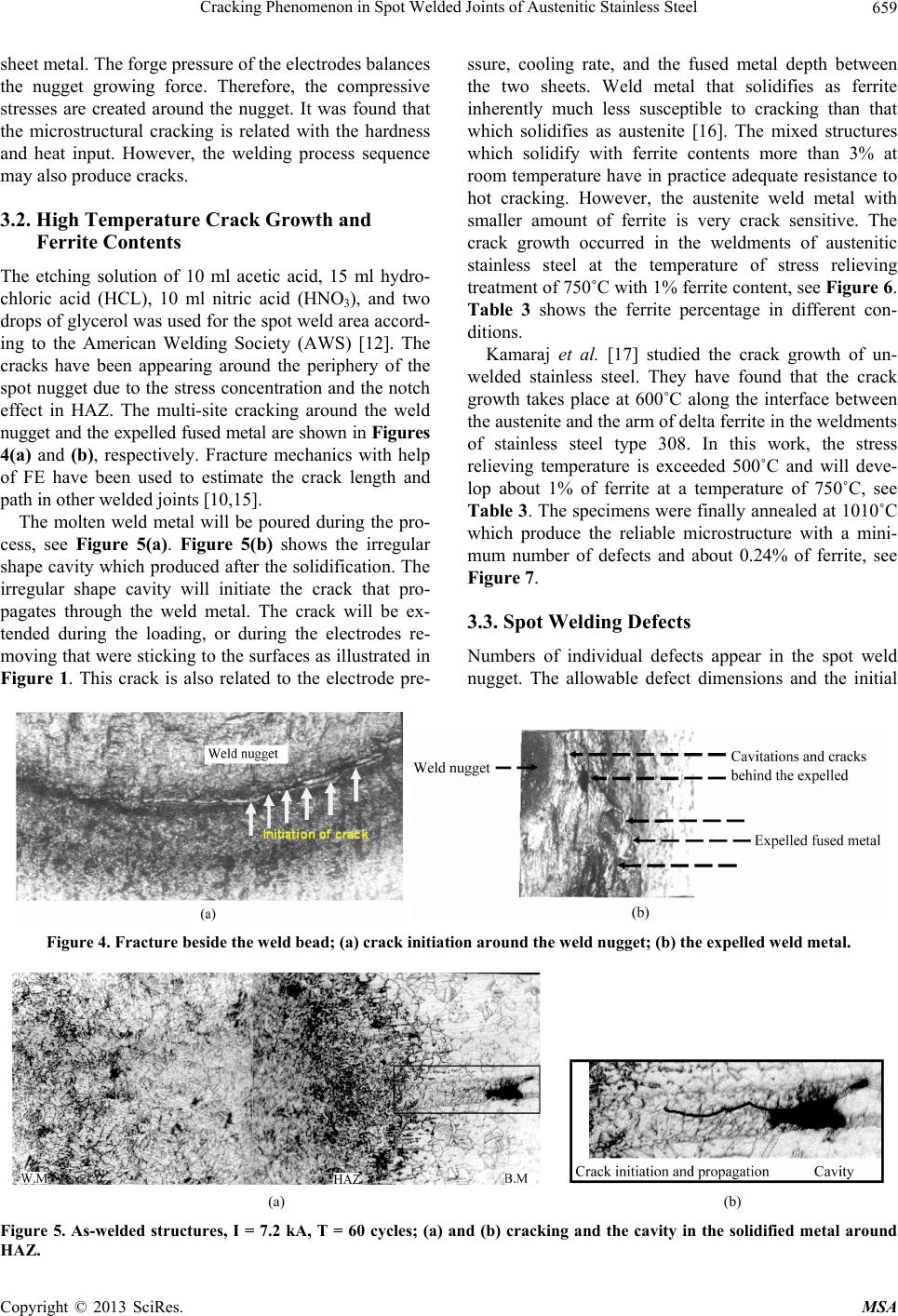
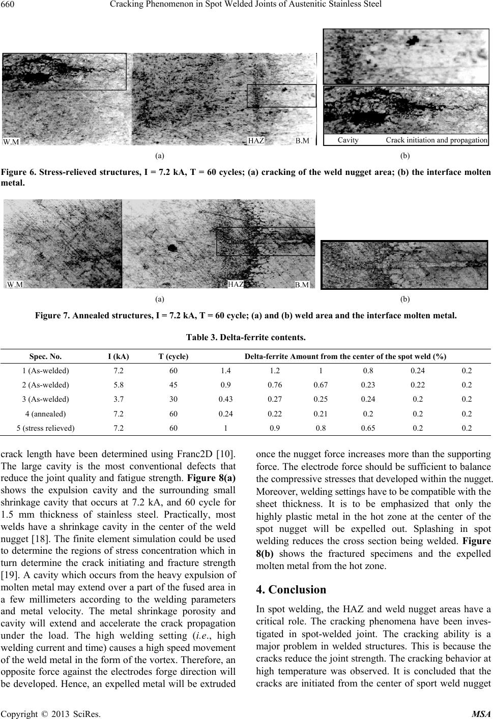
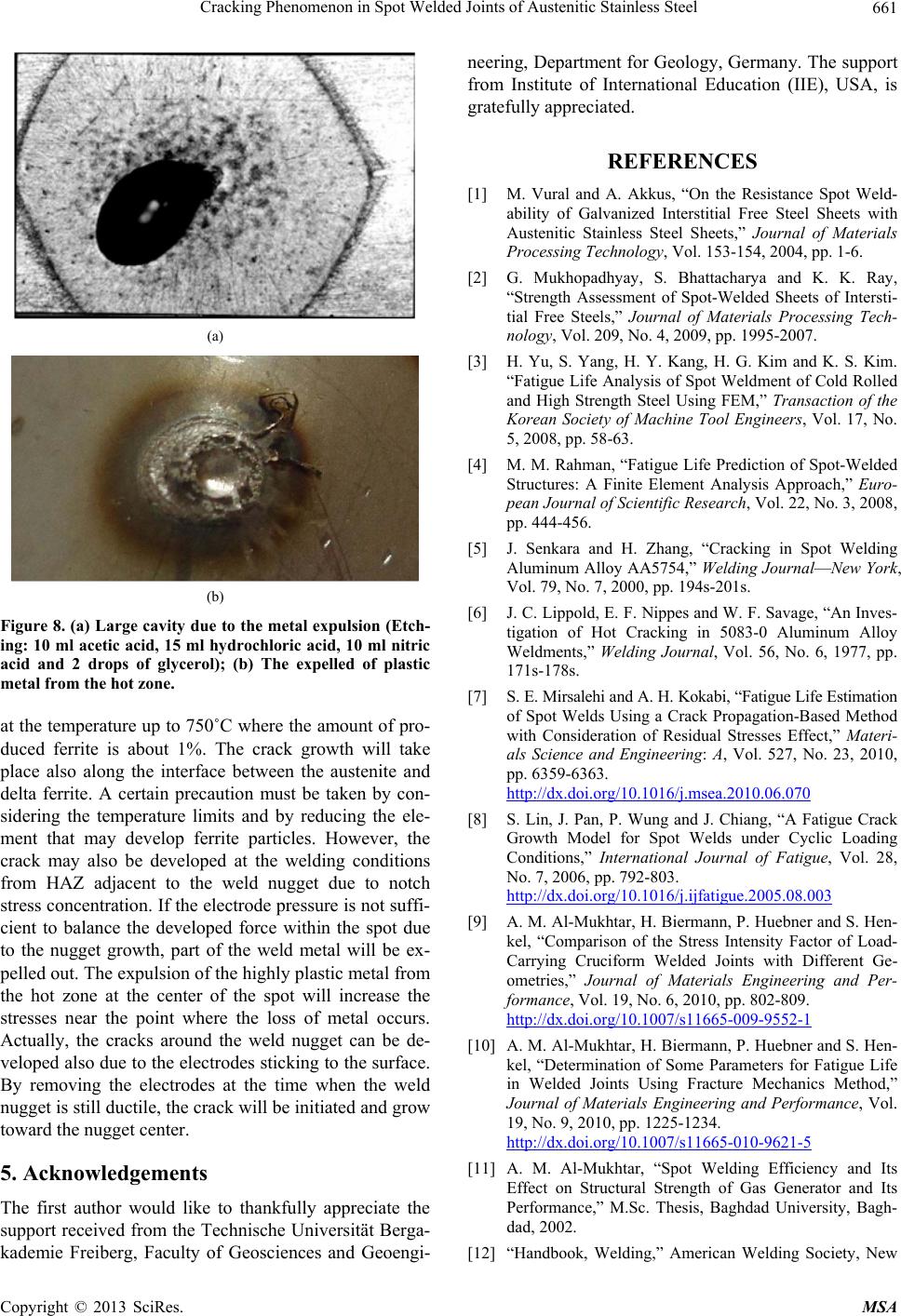
Figure 8. (a) Large cavity due to the metal expulsion (Etch-
ing: 10 ml acetic acid, 15 ml hydrochloric acid, 10 ml nitric
acid and 2 drops of glycerol); (b) The expelled of plastic
metal from the hot zone.
at the temperature up to 750˚C where the amount of pro-
duced ferrite is about 1%. The crack growth will take
place also along the interface between the austenite and
delta ferrite. A certain precaution must be taken by con-
sidering the temperature limits and by reducing the ele-
ment that may develop ferrite particles. However, the
crack may also be developed at the welding conditions
from HAZ adjacent to the weld nugget due to notch
stress concentration. If the electrod e pressure is not suffi-
cient to balance the developed force within the spot due
to the nugget growth, part of the weld metal will be ex-
pelled out. The expulsio n of the highly p lastic metal from
the hot zone at the center of the spot will increase the
stresses near the point where the loss of metal occurs.
Actually, the cracks around the weld nugget can be de-
veloped also due to the electrodes sticking to the surface.
By removing the electrodes at the time when the weld
nugget is still ductile, th e crack will b e initiated and grow
toward the nugget center.
5. Acknowledgements
The first author would like to thankfully appreciate the
support received from the Technische Universität Berga-
kademie Freiberg, Faculty of Geosciences and Geoengi-
neering, Department for Geology, Germany. The support
from Institute of International Education (IIE), USA, is
gratefully appreciated.
REFERENCES
[1] M. Vural and A. Akkus, “On the Resistance Spot Weld-
ability of Galvanized Interstitial Free Steel Sheets with
Austenitic Stainless Steel Sheets,” Journal of Materials
Processing Technology, Vol. 153-154, 2004, pp. 1-6.
[2] G. Mukhopadhyay, S. Bhattacharya and K. K. Ray,
“Strength Assessment of Spot-Welded Sheets of Intersti-
tial Free Steels,” Journal of Materials Processing Tech-
nology, Vol. 209, No. 4, 2009, pp. 1995-2007.
[3] H. Yu, S. Yang, H. Y. Kang, H. G. Kim and K. S. Kim.
“Fatigue Life Analysis of Spot Weldment of Cold Rolled
and High Strength Steel Using FEM,” Transaction of the
Korean Society of Machine Tool Engineers, Vol. 17, No.
5, 2008, pp. 58-63.
[4] M. M. Rahman, “Fatigue Life Prediction of Spot-Welded
Structures: A Finite Element Analysis Approach,” Euro-
pean Journal of Scientific Research, Vol. 22, No. 3, 2008,
pp. 444-456.
[5] J. Senkara and H. Zhang, “Cracking in Spot Welding
Aluminum Alloy AA5754,” Welding JournalNew York,
Vol. 79, No. 7, 2000, pp. 194s-201s.
[6] J. C. Lippold, E. F. Nippes and W. F. Savage, “An Inves-
tigation of Hot Cracking in 5083-0 Aluminum Alloy
Weldments,” Welding Journal, Vol. 56, No. 6, 1977, pp.
171s-178s.
[7] S. E. Mirsalehi a nd A. H. Koka bi, “Fatigue Life Estimatio n
of Spot Welds Using a Crack Propagation-Based Method
with Consideration of Residual Stresses Effect,” Materi-
als Science and Engineering: A, Vol. 527, No. 23, 2010,
pp. 6359-6363.
http://dx.doi.org/10.1016/j.msea.2010.06.070
[8] S. Lin, J. Pan, P. Wung and J. Chiang, “A Fatigue Crack
Growth Model for Spot Welds under Cyclic Loading
Conditions,” International Journal of Fatigue, Vol. 28,
No. 7, 2006, pp. 792-803.
http://dx.doi.org/10.1016/j.ijfatigue.2005.08.003
[9] A. M. Al-Mukhtar, H. Biermann, P. Huebner and S. Hen-
kel, “Comparison of the Stress Intensity Factor of Load-
Carrying Cruciform Welded Joints with Different Ge-
ometries,” Journal of Materials Engineering and Per-
formance, Vol. 19, No. 6, 2010, pp. 802-809.
http://dx.doi.org/10.1007/s11665-009-9552-1
[10] A. M. Al-Mukhtar, H. Biermann, P. Huebner and S. Hen-
kel, “Determination of Some Parameters for Fatigue Life
in Welded Joints Using Fracture Mechanics Method,”
Journal of Materials Engineering and Performance, Vol.
19, No. 9, 2010, pp. 1225-1234.
http://dx.doi.org/10.1007/s11665-010-9621-5
[11] A. M. Al-Mukhtar, “Spot Welding Efficiency and Its
Effect on Structural Strength of Gas Generator and Its
Performance,” M.Sc. Thesis, Baghdad University, Bagh-
dad, 2002.
[12] “Handbook, Welding,” American Welding Society, New
Copyright © 2013 SciRes. MSA
Cracking Phenomenon in Spot Welded Joints of Austenitic Stainless Steel
Copyright © 2013 SciRes. MSA
662
York, 1978.
[13] American Society for Metals, “Metal Handbook: Welding
and Brazing,” 8th Edition, ASM International, Materials
Park, 1971.
[14] A. I. Pugachev, N. B. Demkin and V. I. Ryazantsev,
“Dimensions of Initial Contact in Spot Welding of Light
Alloys,” Welding Research Abroad, April 1969, pp. 72-
76.
[15] A. M. Al-Mukhtar, H. Biermann, P. Huebner and S. Hen-
kel, “The Effect of Weld Profile Geometries of Butt Weld
Joints on Fatigue Life under Cyclic Tensile Loading,”
Journal of Materials Engineering and Performance, Vol.
20, No. 8, 2011, pp. 1385-1391.
http://dx.doi.org/10.1007/s11665-010-9775-1
[16] J. F. Lancaster, “The Metallurgy of Welding, Brazing and
Soldering,” George Alden and Unwin LTD., London,
1970.
[17] M. Kamaraj and V. M. Radhakrishnan, “High Tempera-
ture Crack Growth in Austenitic Weld Metal,” Engineer-
ing Fracture Mechanics, Vol. 33, No. 5, 1989, pp. 801-
811.
[18] Q. Doos and A. M. Al-Mukhtar, “Static Strength Behav-
ior of Austenitic Stainless Steel Sheet,” Journal of Engi-
neering College, Baghdad University, Vol. 10, No. 2,
2004.
[19] A. M. Al-Mukhtar, “Investigation of the Thickness Effect
on the Fatigue Strength Calculation,” Journal of Failure
Analysis and Prevention, Vol. 13, No. 1, 2013, pp. 63-71.
http://dx.doi.org/10.1007/s11668-012-9629-2