Modeling and Numerical Simulation of Material Science, 2013, 3, 1-5
doi:10.4236/mnsms.2013.34B001 Published Online October 2013 (http://www.scirp.org/journal/mnsms)
The Influence of Sheath Solvent’s Flow Rate on the
Quality of Electrospun Ethyl Cellulose Nanofibers
Deng-Guang Yu*, Xiong-Xiu Li, Jia-Wen Ge, Peng-Peng Ye, Xia Wang*
School of Materials Science & Engineering, University of Shanghai for Science and Technology, Shanghai, China
Email: *ydg017@usst.edu.cn, *wangxia@usst.edu.cn
Received May, 2013
ABSTRACT
The present research investigates the influence of sheath solvent’s flow rate on the quality of electrospun ethyl cellulose
(EC) nanofibers using a modified coaxial process. With 24 w/v % EC in ethanol as electrospinnable core fluid and
ethanol as sheath fluid, EC nanofibers generated under different sheath flow rates were generated from the modified
processes. FESEM observations demonstrate that the modified process is effective in preventing the clogging of spin-
neret for a smooth electrospinning. The key for the modified coaxial process is the reasonable selection of a sheath flow
rate matching the drawing process of core EC fluid during the electrpospinning. The EC nanofibers’ diameters (D, nm)
could be manipulated through the sheath-to-core flow rate ratio (f) as D = 819-1651f (R= 0.9754) within a suitable range
of 0 to 0.25. The present paper provides useful data for the implementation of the modified coaxial process controllably
to obtain polymer nanofibers with high quality.
Keywords: Coaxial Electrospinning; Nanofibers; Ethyl Cellulose; Sheath Fluids; Flow rate
1. Introduction
Ethylcellulose (EC) is a derivative of cellulose in which a
defined percentage of the hydroxyl groups of the repeating
glucose units are substituted with ethyl ether groups. It
fulfills all the requirements of major pharmacopoeias
(USP, EP, and JP) and food regulations. EC is an inert,
hydrophobic polymer and is essentially tasteless, odorless,
colorless, non-caloric, and physiologically inert. It has
long been used as solvent-based tablet and pellet coating,
tablet binder, to prepare microcapsules and microspheres,
and both as film and matrix-forming material for
sustained- release dosage forms [1]. Most recently, EC
was selected as the drug carrier and polymer matrix to
generate composite fibers and microparticles to achieve
sustained-release profiles [1,2].
All the above-mentioned EC-based functional nano-
materials were generated using a single fluid electrohy-
drodynamic atomization process (including electrospin-
ning, electrospraying and e-jetting printing), which is a
popular procedure for producing nanofibers or micropar-
ticles due to ease of implementation and cost-effective-
ness, and the unique properties and versatile applications
of the resultant products [1-3]. Although electrospinning
is simple and straightforward, the mechanism of fiber
formation involves complex electro-fluid-mechanical
issues and there are many factors that can affect the fiber
diameters and morphology. Controlled production of
electrospun nanofibers with uniform diameter and struc-
ture remains a challenge [4,5]. To ensure a successful
electrospinning process, the chain-entanglement density
in the working solution must be high enough to prevent
the capillary breakup and also to subdue Rayleigh insta-
bility. However, high concentration polymer solutions
often result in clogging of the spinneret and failure of the
electrospinning process. Thus polymers often have nar-
row windows of electrospinnable solution concentrations,
and the objective of obtaining finer structures (such as by
lowering polymer concentration, by adding salt or sur-
factant, and by manipulating the electrospinning pa-
rameters) is often limited and compromised by sacrific-
ing the fiber uniformity [6,7].
Clogging is a critical but common problem experi-
enced during the traditional single fluid electrospinning,
especially when a high-volatility solvent is used to pre-
pare a polymer solution. With zein as model, Kanjan-
apongkul [8,9] reported that clogging would occur even
when the zein concentration in its ethanol aqueous solu-
tions (85 wt %) decreased from an electrospinning level
to electrospraying level (< 18 wt %), 16 wt % and 10 wt
% zein solutions were also tested. It was found that clog-
ging was still observed in both cases. They have put for-
ward a method to prevent clogging simply by providing
an additional solvent through another syringe pump onto
the surface of the droplet at the needle tip. But this
*Corresponding author.
Copyright © 2013 SciRes. MNSMS
D.-G. YU ET AL.
2
method is difficult for precise control of the process, be-
cause the additional solvent was put on the needle tip
simply by gravity.
Coaxial electrospinning, in which a concentric spin-
neret can accommodate two different liquids, is regarded
as one of the most significant breakthroughs in this area
[10,11]. It has been applied broadly in controlling secon-
dary structures of nanofibers, encapsulating drugs or
biological agents into the polymer nanofibers, preparing
nanofibers from materials that lack filament-forming
properties, enclosing functional liquids within the fiber
matrix, manipulating the size of self-assembled nanopar-
ticles, and preparing ultrafine fibers from concentrated
polymer solutions. It is a common sense that the sheath
fluids must have enough viscosity to overcome the inter-
facial tension between the two solutions through “viscous
dragging” and “contact friction” for a successful coaxial
electrospinning process [11]. However, our group have
broken this concept and developed a modified coaxial
electrospinning process, in which only organic solvent
was used as sheath fluid. This opens a new way for ma-
nipulating the additional solvent to accompany the elec-
trospinnable fluids in a core-sheath and controllable way,
and thus should provide new possibility in controlling the
nanofiber-forming process and also the nanofibers’ quality.
2. Experimental
2.1. Materials
EC (6 mPa·s to 9 mPa·s) was obtained from Aladdin
Chemistry Co., Ltd (Shanghai, China). Methylene blue
and anhydrous ethanol were purchased from Sinopharm
Chemical Reagent Co., Ltd. (Shanghai, China). All other
chemicals used were analytical grade.
2.2. Coaxial Electrospinning
The core solutions were prepared by dissolving 24 g EC,
3 g KET and 2 mg methylene blue in 100 mL ethanol.
The sheath solvent was pure ethanol. Two syringe pumps
(KDS100 and KDS200, Cole-Parmer, IL, USA) and a
high-voltage power supply (ZGF 60kV/2 mA, Shanghai
Sute Corp., Shanghai, China) were used for coaxial elec-
trospinning. All electrospinning processes were carried
out under ambient conditions (21 ± 2 with a relative
humidity 64% ± 6%). A homemade concentric spinneret
was used to conduct the coaxial electrospinning proc-
esses. A stainless steel capillary with an inner diameter
of 0.3 mm was used to conduct the single fluid electro-
spinning.
The electrospinning process was recorded using a dig-
ital video recorder (PowerShot A490, Canon, Tokyo,
Japan). For optimization, the applied voltage was fixed at
14 kV, and the fibers were collected on an aluminum foil
at a distance of 20 cm. All other parameters are listed in
Table 1.
2.3. Characterization
The surface morphologies of electrospun fibers were
assessed using a JSM-5600LV scanning electron micro-
scope (SEM, Japan Electron Optics Laboratory Co. Ltd.).
Prior to the examination, the samples were gold sputter-
coated under argon atmosphere to render them electri-
cally conductive. The pictures were then taken at an ex-
citation voltage of 3 kV. The average fiber diameter was
determined by measuring diameters of fibers at over 100
different locations from the same SEM images using
Image J software (National Institutes of Health, USA).
3. Results and Discussion
A schematic diagram of the modified coaxial electro-
spinning process with solvent as sheath fluid is shown in
Figure 1(a). A homemade concentric spinneret was used
to carry out the modified process (Figure 1(b)). The criti-
cal voltage applied to a fluid to initiate Taylor cone forma-
tion and the straight thinning jet (Vc) have a close rela-
tionship with the diameter of sheath part of the concen-
tric spinneret [12].
2
~
cd
VR
Where Vc is the critical voltage for a jet emanating
from the meniscus tip, d is the electrode separation, ε is
the permittivity, γ is the surface tension, and R is the
principal curvature of the liquid meniscus. A small
Table 1. Parameters of EC nanofibers and their preparation.
Flow rate (ml/h)
No.
Sheath Core
Rsa Morphologyb Diameter
(µm)
F1Single fluid spinning Line 0.42±0.18
F20.1 0.9 0.11 Line 0.34±0.15
F30.2 0.8 0.25 Line 0.23±0.14
F40.3 0.7 0.43 Mixed --
aRsc Sheath-to-core flow rate ratio; bIn this column, “Line” morphology
refers to that nanofibers have few beads or spindles on them; “Mixed” mor-
phology refers to that there are beads/spindles on the nanofibes.
Figure 1. The modified coaxial electrospinning: (a) Sche-
matic diagram of the modified process; (b) The homemade
concentric spinneret.
Copyright © 2013 SciRes. MNSMS
D.-G. YU ET AL. 3
diameter of the spinneret’s orifice means a small R, and
thus a small Vc to imitate the coaxial electrospinning
process. The homemade spinneret here has an out and
inner diameter of 1.2 and 0.3 mm respectively (Figure
1(b)), facilitating the coaxial electrospinning process. In
addition, the inner capillary is a little project out the
sur-face of the out capillary, which should help to make
the sheath ethanol well surround the core EC solutions.
When a single fluid electrospinning of the EC solu-
tions was conducted using a stainless steel capillary, the
spin-neret was clogged from time to time, as shown in
Figure 2(a). Manual remove of semi-solid substance
hung on the nozzle of the spinneret was needed to keep
the electro-spinning process go on. The fast evaporation
of ethanol on the surface of fluid jet led to the formation
of a highly viscous semi-solid substance, which clung to
the nozzle of spinneret and thus retarded the electrospin-
ning process.
When the modified coaxial electrospinning was car-
ried out to prepare the EC nanofibers, two syringe pumps
were used to drive the sheath and core fluids independ-
ently. An alligator clip was used to connect the inner
stainless steel capillary with the high voltage supply
(Figure 2(b)). With ethanol as sheath fluid and under a
sheath-to-core flow rate ratio of 0.25, the arrangement
produced a typical fluid jet trajectory, in which a Taylor
cone followed by a straight fluid jet and a bending and
whipping instability region (Figure 2(c)). The compound
Taylor cone is clear to be composed of two parts with the
sheath solvent well surrounding the core polymer solu-
tions, indicating by the methylene blue in Figure 2 (d).
The coaxial electrospinning process could be car-ried
out without any clogging phenomena and go on smoothly
for finishing the electrospinning of the whole EC solu-
tion in the syringe. Solvent evaporation and vis-cosity of
Figure 2. Observations of the modified coaxial electrospin-
ning and a single fluid process: (a) a typical clogging of the
single fluid electrospinning; (b) a digital picture shows the
connection of the concentric spinneret with the syringe
pump and the power supply; (c) a typical coaxial electro-
spinning process with ethanol as sheath fluid and under a
sheath-to-core flow rate ratio of 0.25 (taken under a magni-
fication of 12×); (d) the compound Taylor cone.
the solution have been noted to have strong impacts on
clogging. High volatility of a solvent accelerates solvent
evaporation, thus increases the likelihood of clogging.
This is because applied electric field cannot overcome
the viscous drag force. If the viscosity is too high, it is
possible that, the higher the solution viscosity is the ap-
plied electrical force would not be adequate to overcome
the viscous drag force at the droplet-air inter-face, lead-
ing to clogging at the spinneret. When sheath ethanol
was exploited to surround the core EC solution during
the electrospinning, the sheath ethanol can effectively
prevent the fast evaporation of the ethanol from the sur-
face of the core EC solutions, retarding the formation of
“skin” surface to smooth the electrospinning of EC solu-
tions.
Nanofibers obtained from the single fluid electro-
spinning and the modified coaxial electrospinning are
showed in Figure 3, and the nanofibers’ diameter distri-
butions are given in Figure 4. All the nanofibers have
linear morphology, except F4 which has a typical beads-
on-a-string morphology resulted from the excessive
sheath solutions (Figure 3 (d)).
Nanofibers F1 obtained from the single fluid elec-
trospinning are showed in Figure 3(a), and the nanofi-
bers had an average diameter of 860 ± 230 nm (Figure
4(a)). Besides a larger diameter, nanofibers F1 also have
a wide distribution of diameters. As the flow rate of
sheath ethanol was increased from 0.1 to 0.2 mL/h, the
resultant nanofibers F2 andF3 were progressively nar-
rower (Figures 3(b) to (c) and Figures 4(b) to (c)), with
Figure 3. FESEM images of EC nanofibers: (a) F1; (b) F2;
(c) F3; (d) F4, the scale bar represents 5 µm.
Figure 4. Nanofiber diameters’ distributions: (a) F1; (b) F2;
(c) F3. The relationships between the EC nanofibers’ diameter
and the sheath-to-core flow rate ratio.
Copyright © 2013 SciRes. MNSMS
D.-G. YU ET AL.
4
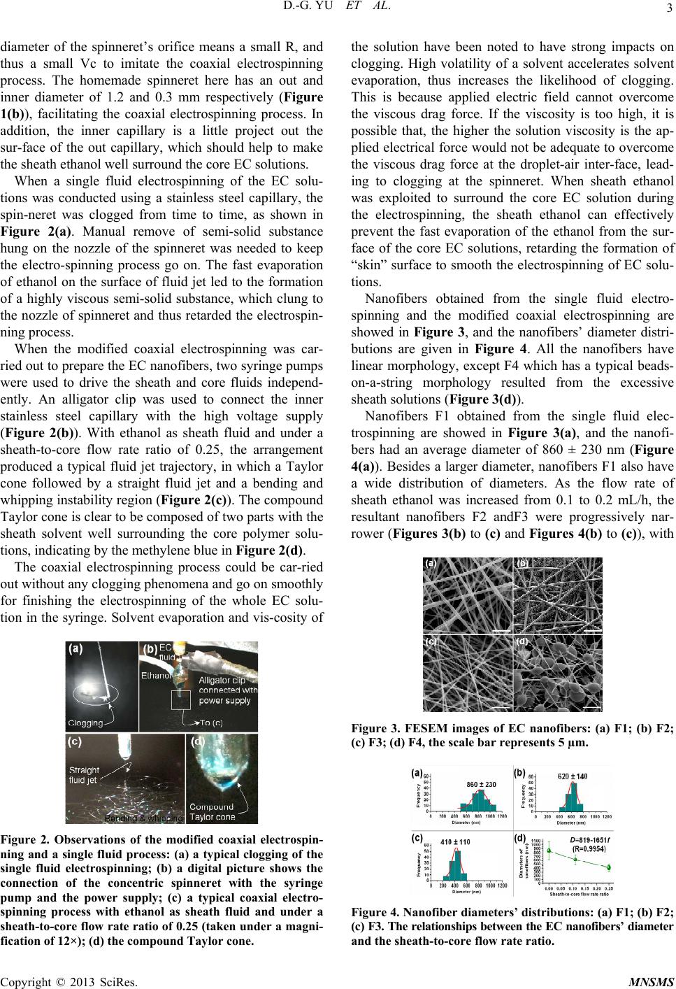
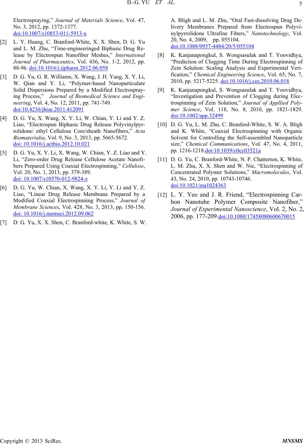
a diameter of 620 ± 140 nm, 410 ± 110 nm, respectively.
Moreover, all had diameters smaller than F1 fibers (Fig-
ure 4(a)) prepared from the single fluid EC solution us-
ing a traditional single fluid electrospinning process.
Both the nanofibers had good structural uniformity and a
relatively small diameter distribution, suggesting a finer
quality of the EC nanofibers. A linear relationship be-
tween the sheath-to-core flow rate ratio (f) and the resul-
tant nano-fibers’ average diameters (D, nm) was found
(Figure 4(d)) within a suitable range. The regressed equ-
ation is D = 819-1651f, with a correlation coefficient of
0.9754. The results suggest that the diameters of uniform
nanofibers can be tailored through manipulating the
sheath flow rates over a suitable range through the modi-
fied coaxial electrospinning.
Throughout the modified coaxial electrospinning, the
sheath solvent would exert the following influences on
the process: 1) facilitating the formation of Taylor cone
due to lower solvent surface tensions; 2) surrounding the
straight thinning jet of the core electrospinnable EC solu-
tions that retards the fast evaporation of the core solvent,
while the sheath solvent itself outwardly evaporates to
the open air; 3) following the core fluid to enter the in-
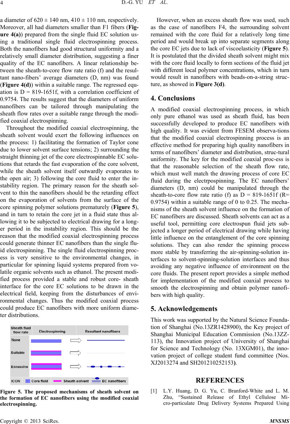
stability region. The primary reason for the sheath sol-
vent to thin the nanofibers should be the retarding effect
on the evaporation of solvents from the surface of the
core spinning polymer solutions prematurely (Figure 5),
and in turn to retain the core jet in a fluid state thus al-
lowing it to be subjected to electrical drawing for a long-
er period in the instability region. This should be the
reason that the modified coaxial electrospinning process
could generate thinner EC nanofibers than the single flu-
id electrospinning. The single fluid electrospinning proc-
ess is very sensitive to the environmental changes, in
particular for spinning liquid systems prepared from vo-
latile organic solvents such as ethanol. The present modi-
fied process provided a stable and robust core- sheath
interface for the core EC solutions to be drawn in the
electrical field, keeping from the disturbances of envi-
ronmental changes. Thus the modified coaxial process
could produce EC nanofibers with more uniform diame-
ter distributions.
Figure 5. The proposed mechanisms of sheath solvent on
the formation of EC nanofibers using the modified coaxial
electrospinning.
However, when an excess sheath flow was used, such
as the case of nanofibers F4, the surrounding solvent
remained with the core fluid for a relatively long time
period and would break up into separate segments along
the core EC jets due to lack of viscoelasticity (Figure 5).
It is postulated that the divided sheath solvent might mix
with the core fluid locally to form sections of the fluid jet
with different local polymer concentrations, which in turn
would result in nanofibers with beads-on-a-string struc-
ture, as showed in Figure 3(d).
4. Conclusions
A modified coaxial electrospinning process, in which
only pure ethanol was used as sheath fluid, has been
successfully developed to produce EC nanofibers with
high quality. It was evident from FESEM observa-tions
that the modified coaxial electrospinning process is an
effective method for preparing high quality nanofibers in
terms of nanofibers’ diameter and distribution, struc-tural
uniformity. The key for the modified coaxial proc-ess is
that the reasonable selection of the sheath flow rate,
which must well match the drawing process of core EC
fluid during the electrpospinning. The EC nanofibers’
diameters (D, nm) could be manipulated through the
sheath-to-core flow rate ratio (f) as D = 819-1651f (R=
0.9754) within a suitable range of 0 to 0.25. The mecha-
nisms of the sheath solvent influence on the formation of
EC nanofibers are discussed. Sheath solvents can act as a
useful tool, permitting core electrospun fluid jets sub-
jected a longer period of electrical drawing while having
little influence on the entanglement of the core spinning
solutions. They can also render the spinning process
more stable by transferring the air-spinning-solution in-
terfaces to solvent-spinning-solution interfaces and thus
avoiding any negative influence of environment on the
core fluids. The present report provides a simple method
for implementation of the modified coaxial process to
smooth the electrospinning and obtain polymer nanofi-
bers with high quality.
5. Acknowledgements
This work was supported by the Natural Science Founda-
tion of Shanghai (No.13ZR1428900), the Key project of
Shanghai Municipal Education Commission (No.13ZZ-
113), the Innovation project of University of Shanghai
for Science and Technology (No. 13XGM01), the inno-
vation project of college student fund committee (Nos.
XJ2013274 and SH201210252153).
REFERENCES
[1] L.Y. Huang, D. G. Yu, C. Branford-White and L. M.
Zhu, “Sustained Release of Ethyl Cellulose Mi-
cro-particulate Drug Delivery Systems Prepared Using
Copyright © 2013 SciRes. MNSMS
D.-G. YU ET AL.
Copyright © 2013 SciRes. MNSMS
5
Electrospraying,” Journal of Materials Science, Vol. 47,
No. 3, 2012, pp. 1372-1377.
doi:10.1007/s10853-011-5913-x
[2] L. Y. Huang, C. Branford-White, X. X. Shen, D. G. Yu
and L. M. Zhu, “Time-engineeringed Biphasic Drug Re-
lease by Electrospun Nanofiber Meshes,” International
Journal of Pharmaceutics, Vol. 436, No. 1-2, 2012, pp.
88-96. doi:10.1016/j.ijpharm.2012.06.058
[3] D. G. Yu, G. R. Williams, X. Wang, J. H. Yang, X. Y. Li,
W. Qian and Y. Li, “Polymer-based Nanoparticulate
Solid Dispersions Prepared by a Modified Electrospray-
ing Process,” Journal of Biomedical Science and Engi-
neering, Vol. 4, No. 12, 2011, pp. 741-749.
doi:10.4236/jbise.2011.412091
[4] D. G. Yu, X. Wang, X. Y. Li, W. Chian, Y. Li and Y. Z.
Liao, “Electrospun Biphasic Drug Release Polyvinylpyr-
rolidone/ ethyl Cellulose Core/sheath Nanofibers,” Acta
Biomaterialia, Vol. 9, No. 3, 2013, pp. 5665-5672.
doi: 10.1016/j.actbio.2012.10.021
[5] D. G. Yu, X. Y. Li, X. Wang, W. Chian, Y. Z. Liao and Y.
Li, “Zero-order Drug Release Cellulose Acetate Nanofi-
bers Prepared Using Coaxial Electrospinning,” Cellulose,
Vol. 20, No. 1, 2013, pp. 379-389.
doi: 10.1007/s10570-012-9824-z
[6] D. G. Yu, W. Chian, X. Wang, X. Y. Li, Y. Li and Y. Z.
Liao, “Linear Drug Release Membrane Prepared by a
Modified Coaxial Electrospinning Process,” Journal of
Membrane Sciences, Vol. 428, No. 3, 2013, pp. 150-156.
doi: 10.1016/j.memsci.2012.09.062
[7] D. G. Yu, X. X. Shen, C. Branford-white, K. White, S. W.
A. Bligh and L. M. Zhu, “Oral Fast-dissolving Drug De-
livery Membranes Prepared from Electrospun Polyvi-
nylpyrrolidone Ultrafine Fibers,” Nanotechnology, Vol.
20, No. 4, 2009, pp. 055104.
doi:10.1088/0957-4484/20/5/055104
[8] K. Kanjanapongkul, S. Wongsasulak and T. Yoovidhya,
“Prediction of Clogging Time During Electrospinning of
Zein Solution: Scaling Analysis and Experimental Veri-
fication,” Chemical Engineering Science, Vol. 65, No. 7,
2010, pp. 5217-5225. doi:10.1016/j.ces.2010.06.018
[9] K. Kanjanapongkul, S. Wongsasulak and T. Yoovidhya,
“Investigation and Prevention of Clogging during Elec-
trospinning of Zein Solution,” Journal of Appllied Poly-
mer Science, Vol. 118, No. 8, 2010, pp. 1821-1829.
doi:10.1002/app.32499
[10] D. G. Yu, L. M. Zhu, C. Branford-White, S. W. A. Bligh
and K. White, “Coaxial Electrospinning with Organic
Solvent for Controlling the Self-assembled Nanoparticle
size,” Chemical Communications, Vol. 47, No. 4, 2011,
pp. 1216-1218.doi:10.1039/c0cc03521a
[11] D. G. Yu, C. Branford-White, N. P. Chatterton, K. White,
L. M. Zhu, X. X. Shen and W. Nie, “Electrospinning of
Concentrated Polymer Solutions,” Macromolecules, Vol.
43, No. 24, 2010, pp. 10743-10746.
doi:10.1021/ma1024363
[12] L. Y. Yeo and J. R. Friend, “Electrospinning Car-
bon Nanotube Polymer Composite Nanofiber,”
Journal of Experimen tal Nanoscience, Vol. 2, No. 2,
2006, pp. 177-209.doi:10.1080/17458080600670015