 Energy and Power Engineering, 2013, 5, 513-522 http://dx.doi.org/10.4236/epe.2013.58056 Published Online October 2013 (http://www.scirp.org/journal/epe) Copyright © 2013 SciRes. EPE Numerical Study on the Hydrogen Fueled SI Engine Combustion Optimization through a Combined Operation of DI and PFI Strategies* Medhat Elkelawy, Hagar Alm-Eldin Bastawissi Department of Mechanical Power Engineering, Tanta University, Tanta, Egypt Email: medhatelkelawy@f-eng.tanta.edu.eg Received August 25, 2013; revised September 25, 2013; accepted October 2, 2013 Copyright © 2013 Medhat Elkelawy, Hagar Alm-Eldin Bastawissi. This is an open access article distributed under the Creative Commons Attribution License, which permits unrestricted use, distribution, and reproduction in any medium, provided the original work is properly cited. ABSTRACT As the practicability of a hydrogen-fueled economy emerges, intermediate technologies would be necessary for the transition between hydrocarbon fueled internal combustion engines and hydrogen powered fuel cells. In the present study, the hydrogen engine efficiency and the load control are the two main parameters that will be improved by using the combined operation of in-cylinder direct fuel injection (DI) and port fuel injection (PFI) strategies to obtain maxi- mum engine power outputs with acceptable efficiency equivalent to gasoline engines. Wide open throttle (WOT) opera- tion has been used to take advantage of the associated increase in engine efficiency, in which the loads have been regu- lated with mixture richness (qualitative control) instead of volumetric efficiency (quantitative control). The capabilities of a 3D-CFD code have been developed and employed to simulate the whole engine physicochemical process which includes the hydrogen injection through the intake manifold (PFI) and/or the hydrogen DI in the engine compression stroke. Conditions with simulated PFI, PFI + DI and DI have been analyzed to study the effects of mixture preparation behaviors on the hydrogen ignition and its flame propagation inside the engine combustion chamber. Numerically, the CFD code has been intensively validated against experimental engine data which provided remarkable agreement in terms of in-cylinder pressure history evaluation. Keywords: Hydrogen Fuel; SI Engine; Port Fuel Injection; Direct Injection; Wide Open Throttle; Kiva-3vr2 1. Introduction Hydrogen engine research topics introduce the engine obstacles such as suffering from abnormal combustion, which has been considered quite challenging, and the re- lated measures to avoid its drawbacks are important for engine design, mixture formation, and load control [1]. For such engines, the hydrogen introducing methods into the engine cylinder determine the engine performance and durability. In this regard, two methods have been used and tested previously, the external and internal mix- ture formation [2]. The injection of water into both suc- tion and compression strokes [3], the late external hy- drogen supply and direct injection are all suggested me- thods to delay or even prevent backfiring by either add- ing a cooling effect or avoiding a combustible mixture during the intake phase. However, external mixture for- mation by means of port fuel injection (PFI) has been demonstrated to result in higher engine efficiencies, ex- tended lean operation, lower cyclic variability and lower NOx production compared to direct fuel injection in compression stroke [4,5]. Thus, it was attributed to en- hancement of the mixture homogeneity due to longer mixing time in the case of PFI fuel supply. However, the mixture preparation is decreased for DI method where the generated turbulence behind the intake valves does not contribute to the mixing process. Hydrogen DI strat- egy is used in high loads conditions coupled with the delaying of injection timing to reduce the significancy of the NOx emissions [6,7]. Basically, when we consider the engine assembly and retrofitting costs, the external mixture formation provides a greater degree of freedom concerning storage methods. Also, DI injectors designs still require more development to obtain high flow rates and reach the robustness needed for the harsh combustion chamber environment condi- tions [8]. Consequently, both external and internal mix- *Optimizing the Hydrogen Engine Performance Techniques.  M. ELKELAWY, H. ALM-ELDIN BASTAWISSI Copyright © 2013 SciRes. EPE 514 ture formations have advantages and disadvantages. DI is better for full load performance; PFI is suggested at part and moderate load conditions [5,9]. Contemporary re- views of mixture formation techniques for hydrogen en- gines can be found in references [10,11] for more details. The optimized operation of the hydrogen-fueled engines can be achieved with a dual injection (PFI + DI) system and throttle valve control [5,12]. In the present study, the engine efficiency and the load control are the two main parameters that will be im- proved by using the hybrid control strategy of PFI + DI, and lean combustion near the engine cylinder wall to obtain maximum engine power outputs with an accept- able efficiency equivalent to gasoline. New simulation capabilities have been implemented into a 3D-CFD Kiva-3vr2 code to simulate the whole engine physico- chemical process which includes the hydrogen jet inter- action with the in-cylinder flow field and its effects on the mixture distribution and homogeneity behind the spark ignition location and the in-cylinder wall. 1.1. Experimental and Numerical Analysis The pressure of the in-cylinder data was measured by a piezoelectric transducer and amplified with the charge amplifier and finally processed by a data acquisition sys- tem. The dynamic top-dead-center (TDC) was estab- lished through the tested engine motoring. The crank angle signal was obtained from an angle-encoder device which mounted on the crank shaft. The signal of the cyl- inder pressure was acquired for every one crank degree, and the acquisition process covered 20 complete succes- sive cycles; the average value of these 20 cycles was outputted as the pressure data used for the calculation of combustion parameters. Wall function for the velocity and temperature within the region in proximity to the walls has been activated in our multidimensional model. Wall function is an analytic solution to simplify turbulence equations which used to calculate wall shear stresses and heat transfer losses. It is used instead of numerical solution of the complete tur- bulence equations near the wall because of the difficul- ties of generating a sufficient engine mesh resolution. The heat transfer derived model is based on the assump- tions of incompressible flows with the perturbation the- ory [13]. However, improved wall function has been used to solve the governing equations which include con- tinuity, momentum, and energy near the cylinder wall [14]. It is employed to the logarithmic law-of-wall to de- fine the velocity and temperature profiles in the near- wall regions. 1.2. Model Governing Equations and Numerical Methods The KIVA-3vr2 code for computational fluid dynamics has been modified and employed to investigate—nu- merically—the hydrogen engine for both the underlying engine physics, which include the hydrogen PFI or/and DI spray dynamics, chemical energy released by fuel combustion, heat transfer flux across the engine bound- ary, and the effects of the in-cylinder flow field on the mixture preparation prior combustion events. However, the code integrates the important principle of physical models which include all the in-cylinder flow field gov- erning equations, gas or liquid spray, combustion behav- iors, turbulence equations, and moving pistons or valve boundaries to simulate the whole internal combustion engine characteristics. The Arbitrary Lagrangian descrip- tion simulation of the hydrogen gas injection, by using an original KIVA spray sub-model, proved to be a compa- rable difficulty to the liquid fuel injection in both diesel and gasoline engines. The primary challenge is the large change of length scale from the flow of gas in the nozzle orifice to the fuel penetration in either intake manifolds or in-cylinder direct injection. The experimental work was carried out by using fuel injection system capable to supply the hydrogen fuel into the intake manifold and the engine cylinder directly from the fuel bottles after using the proper pressure regulator and valves to adjust the fuel line pressure and flow rate. The original liquid fuel injection model is replaced by developing a new sub-model program. The new sub- model program simulates the hydrogen injection process as a Eularian phase description through a new boundary condition which represents the nozzle configuration and its location. It is adjusted to set the inlet velocity of the gas fuel injection boundary as a value known by either experimental tests or the gas dynamic calculation of the injector nozzle. The modification depends on the use of regions where each region has the same or different inlet condition. So, in order to get multiple inlets, it is neces- sary to define a new region which is used as the injector nozzle configuration. This modification enables the use of the suggested model to simulate the gas fuel supply with the hybrid suggested techniques to study the inter- action of the intake manifold and the in-cylinder flow on the homogeneity of fuel/air mixture prior to the combus- tion event. Further details about KIVA-3vr2 code can be found in the original technical report of Los Alamos Na- tional Laboratory [13,14]. Table 1 lists the main specifi- cations of our engine. During our simulation, the engine speed was kept con- stant at 1500 rpm and the engine load was controlled qualitatively with the mixture richness in which the throttling valve was removed (WOT). More information about the location of the ignition point, the location of the nozzle outlet of the injector used the figure of the combustion chamber and the strength of the swirl, squish and tumble in the combustion chamber can be found in  M. ELKELAWY, H. ALM-ELDIN BASTAWISSI Copyright © 2013 SciRes. EPE 515 Table 1. Engine specifications. Bore × Stroke 76.0 mm × 88.0 mm Connecting-Rod length 131.0 mm Displacement Volume 415 cm3 Compression Ratio 14 Number of Valves 2 for Intake & 2 for Exhaust Intake Valve Open/Close 12˚ BTDC/48˚ ABDC Intake Valve Diameter 29.0 mm Exhaust Valve Open/Close 45˚ BBDC/10˚ ATDC Exhaust Valve Diameter 27.0 mm Hydrogen Nozzle Diameter 5.0 mm Piston Shape Spherical Piston Dish Combustion Chamber Shape Pent-Roof the engine reference manual [15]. 2. Results and Discussion At the base case study, the three examined strategies of hydrogen fuel supply systems are simulated at fixed en- gine speed and air-fuel equivalence ratio of 1500 rpm and 0.52, respectively. The results of the in-cylinder mixture formation in the cases of port fuel injection (PFI), in-cylinder direct injection (DI), and the hybrid technique (PFI + DI) types are represented as a function of hydro- gen concentration and air-fuel equivalence ratio distribu- tion in Figure 1. The designed hybrid technique is ad- justed in our case to supply 30% of the total amount of hydrogen which corresponds to the air-fuel equivalence ratio of 0.52 with a wide-open-throttle by using a direct injection. The hydrogen injector is held open a period of 65 crank angle degree and the end of injection [EOI] timing is adjusted at 40 crank angle degrees BTDC in the engine compression stroke. The port fuel injection strat- egy is adjusted to open the hydrogen injector after clos- ing the exhaust valve through suction stroke with 10 crank angle degrees and the injection duration is adjusted to 45 crank angle degrees. As shown in Figure 1, the flow structure through the intake manifold and behind the intake valves inside the cylinder enhances further mixing properties of the hy- drogen air mixture. The manifold hydrogen injection timing and duration have been studied in order to opti- mize the hydrogen air mixture homogeneity and the en- gine efficiency. The earlier timing and shorter duration of hydrogen injection will produce insufficient mixture homogeneity inside the engine cylinder. Also, the engine volumetric efficiency and the possibility of engine back- fire will be reduced. In addition, the late timing and pro- longing the injection duration will cause a high-quality of mixture preparation while the engine volumetric effi- ciency and back fir probability will be increased. That problem is related to the buoyancy and diffusion of hy- drogen in a confined space such as the engine cylinder where the hydrogen clouds can be accumulated together as shown in Figure 1 in the case of PFI and PFI + DI strategy. The demonstration shown in Figure 1 presents the simulation results from kiva-3vr2 code for hydrogen clouds and plumes being released into the engine cylin- der which is filled with air. The portion of the 3-D plot of the cylinder volume has been removed to make the clouds and injected plumes visible. At the beginning of the simulation, the hydrogen clouds in the case of PFI flew into the cylinder to react with the flow field which was created behind the intake valves. Those clouds col- lected together to form a single cloud which rose quickly to the upper region of engine cylinder and then spread out and began to fill the cylinder volume with hydrogen from the top to the bottom. The final cloud consisted of a rich hydrogen region under the intake valves position (Figure 1 PFI Case) on the upper left side of the chamber. As a result, the equivalence ratio at the spark plug loca- tion is almost less than 0.4 and the hydrogen concentra- tion were visibly decreased near the spark plug location and the cloud itself deflected toward the cylinder wall. In the case of hydrogen DI, the hydrogen fuel is re- leased into the engine cylinder as a plume (or jet). That plume starts to expand vertically along the cylinder vol- ume until it reaches the piston bowl to get depressed ver- tically and expand in the horizontal direction towards the cylinder wall. By this method, the air-hydrogen equiva- lence ratio distribution is concentrated at the central re- gion of the cylinder volume to form a higher value of an equivalence ratio than a whole cylinder average value which is adjusted herein to be 0.52. So, the hybrid tech- nique will take the benefits of other types (PFI, and DI) through injecting a certain percentage of the hydrogen fuel by DI method while the remaining will be supplied by using PFI method. However, by using the hybrid technique, the hydrogen fuel concentration at the spark plug location is quite enough to form a sufficient hydro- gen flame. The flame of hydrogen fuel is characterized as a higher burning velocity and shorter quenching gap (or quenching distance), which is the main cause of reducing the thermal efficiency of hydrogen-fueled engines in comparison with conventionally fueled engines. Thus, the quenching gap of hydrogen is approximately three times less than that of other fuels, such as gasoline. Therefore, hydrogen flames will travel closer to the cyl- inder wall before they are extinguished and this makes it more difficult to quench than gasoline flames. This smaller quenching distance can also increase the ten- dency for backfire since the flame from a hydrogen-air mixture can get past a nearly closed intake valve more readily than the flame from a hydrocarbon-air mixture.  M. ELKELAWY, H. ALM-ELDIN BASTAWISSI Copyright © 2013 SciRes. EPE 516 Figure 1. Mixture formations as a function of an air-fuel equivalence ratio of the three tested cases at different crank angle positions, PFI + 30% DI ratio, total equivalence ratio 0.52, EOI at 40 crank angle degrees BTD, DI duration is 65 crank angle degrees, and engine speed of 1500 rpm. So, our proposed techniques of hybrid fuel supply will reduce the hydrogen concentration close to the cylinder wall (as shown in Figure 1) and enhance a further dis- tribution of the fuel inside the combustion chamber prior to the start of ignition events. Figure 2 shows the relationship between the in-cyl- inder pressure and temperature with the engine crank rotation angle at three different operating methodologies which are introduced in Figure 1. The in-cylinder aver- age pressure curves show a pronounced difference in both the in-cylinder pressure trace during the engine compression stroke and the crank angle corresponding to a maximum cylinder pressure where hydrogen DI me- thod causes a significant rise of the in-cylinder pressure during the compression stroke. This results, is reflecting the effect of hydrogen direct injection on increasing the cylinder charge mass and its pressure which will increase the pumping loss of the cycle when we compare it with the PFI case. However, the engine pumping losses were calculated by consider the required piston work only, which is done against the direct injection mass flow and its pressure rise effect into the engine during compres- sion stroke. The tested engines are designed to minimize the restriction of air flowing into the engine during suc- tion stroke so that the air can be drawn into the cylinder as close as possible to atmospheric pressure. 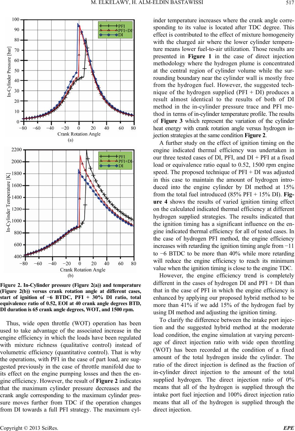 M. ELKELAWY, H. ALM-ELDIN BASTAWISSI Copyright © 2013 SciRes. EPE 517 (a) (b) Figure 2. In-Cylinder pressure (Figure 2(a)) and temperature (Figure 2(b)) versus crank rotation angle at different cases, start of ignition of −6 BTDC, PFI + 30% DI ratio, total equivalence ratio of 0.52, EOI at 40 crank angle degrees BTD, DI duration is 65 crank angle degrees, WOT, and 1500 rpm. Thus, wide open throttle (WOT) operation has been used to take advantage of the associated increase in the engine efficiency in which the loads have been regulated with mixture richness (qualitative control) instead of volumetric efficiency (quantitative control). That is why the operations, with PFI in the case of part load, are sug- gested previously in the case of throttle manifold due to its effect on the engine pumping losses and then the en- gine efficiency. However, the result of Figure 2 indicates that the maximum cylinder pressure decreases and the crank angle corresponding to the maximum cylinder pres- sure moves further from TDC if the operation changes from DI towards a full PFI strategy. The maximum cyl- inder temperature increases where the crank angle corre- sponding to its value is located after TDC degree. This effect is contributed to the effect of mixture homogeneity with the charged air where the lower cylinder tempera- ture means lower fuel-to-air utilization. Those results are presented in Figure 1 in the case of direct injection methodology where the hydrogen plume is concentrated at the central region of cylinder volume while the sur- rounding boundary near the cylinder wall is mostly free from the hydrogen fuel. However, the suggested tech- nique of the hydrogen supplied (PFI + DI) produces a result almost identical to the results of both of DI method in the in-cylinder pressure trace and PFI me- thod in terms of in-cylinder temperature profile. The results of Figure 3 which represent the variation of the cylinder heat energy with crank rotation angle versus hydrogen in- jection strategies at the same condition Figure 2. A further study on the effect of ignition timing on the engine indicated thermal efficiency was undertaken in our three tested cases of DI, PFI, and DI + PFI at a fixed load or equivalence ratio equal to 0.52, 1500 rpm engine speed. The proposed technique of PFI + DI was adjusted in this case to maintain the amount of hydrogen intro- duced into the engine cylinder by DI method at 15% from the total fuel introduced (85% PFI + 15% DI). Fig- ure 4 shows the results of varied ignition timing effect on the calculated indicated thermal efficiency at different hydrogen supplied strategies. The results indicated that the ignition timing has a significant influence on the en- gine indicated thermal efficiency for all of tested cases. In the case of hydrogen PFI method, the engine efficiency increases with retarding the ignition timing angle from −11 to −6 BTDC to be more than 40% while more retarding will reduce the engine efficiency to reach its minimum value when the ignition timing is close to the engine TDC. However, the engine efficiency trend is completely different in the cases of hydrogen DI and PFI + DI than that in the case of PFI in which the engine efficiency is enhanced by applying our proposed hybrid method to be more than 41% if we add 15% of the hydrogen fuel by using DI method and adjusting the ignition timing. To clarify the difference between the intake port injec- tion and the suggested hybrid method at the moderate load condition, the engine simulation at varying percent- age of direct injection ratio with wide open throttling (WOT) has been recorded at the condition of a fixed amount of the total hydrogen inside the cylinder. The ratio of the direct injection is defined as the fraction of in-cylinder direct injection to the amount of the total supplied hydrogen. The direct injection ratio of 0% means that all of the hydrogen is supplied through the intake port fuel injection and 100% direct injection ratio means that all of the hydrogen is supplied through the direct injection. 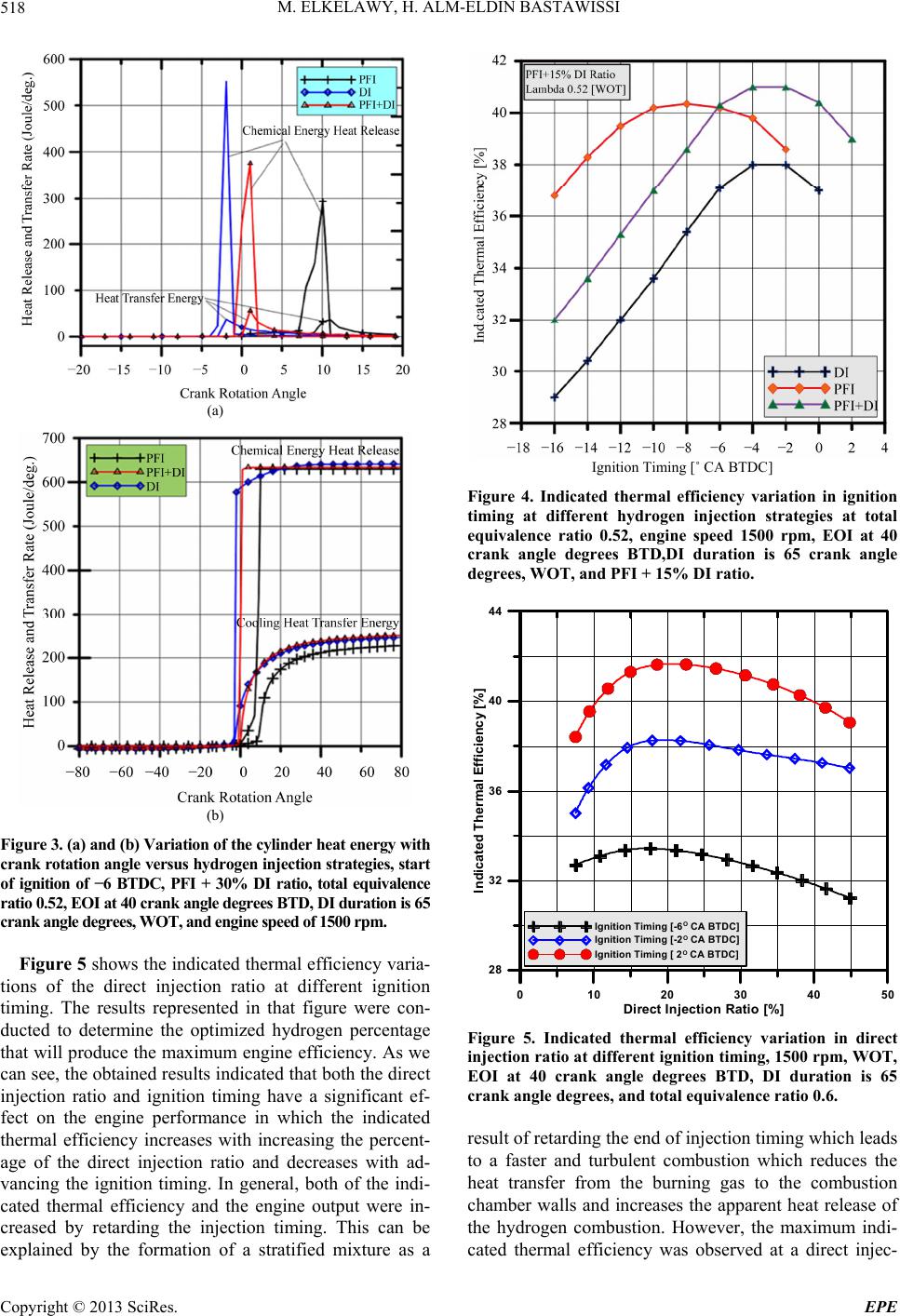 M. ELKELAWY, H. ALM-ELDIN BASTAWISSI Copyright © 2013 SciRes. EPE 518 (a) (b) Figure 3. (a) and (b) Variation of the cylinder heat energy with crank rotation angle versus hydrogen injection strategies, start of ignition of −6 BTDC, PFI + 30% DI ratio, total equivalence ratio 0.52, EOI at 40 crank angle degrees BTD, DI duration is 65 crank angle degrees, WOT, and engine speed of 1500 rpm. Figure 5 shows the indicated thermal efficiency varia- tions of the direct injection ratio at different ignition timing. The results represented in that figure were con- ducted to determine the optimized hydrogen percentage that will produce the maximum engine efficiency. As we can see, the obtained results indicated that both the direct injection ratio and ignition timing have a significant ef- fect on the engine performance in which the indicated thermal efficiency increases with increasing the percent- age of the direct injection ratio and decreases with ad- vancing the ignition timing. In general, both of the indi- cated thermal efficiency and the engine output were in- creased by retarding the injection timing. This can be explained by the formation of a stratified mixture as a Ignition Timing [˚ CA BTDC] Figure 4. Indicated thermal efficiency variation in ignition timing at different hydrogen injection strategies at total equivalence ratio 0.52, engine speed 1500 rpm, EOI at 40 crank angle degrees BTD,DI duration is 65 crank angle degrees, WOT, and PFI + 15% DI ratio. 0 1020304050 Direct In j ecti o n Rati o [%] 28 32 36 40 44 Indicated Thermal Efficiency [%] IgnitionTiming [-6O CA BTDC] IgnitionTiming [-2O CA BTDC] IgnitionTiming [ 2O CA BTDC] Figure 5. Indicated thermal efficiency variation in direct injection ratio at different ignition timing, 1500 rpm, WOT, EOI at 40 crank angle degrees BTD, DI duration is 65 crank angle degrees, and total equivalence ratio 0.6. result of retarding the end of injection timing which leads to a faster and turbulent combustion which reduces the heat transfer from the burning gas to the combustion chamber walls and increases the apparent heat release of the hydrogen combustion. However, the maximum indi- cated thermal efficiency was observed at a direct injec- 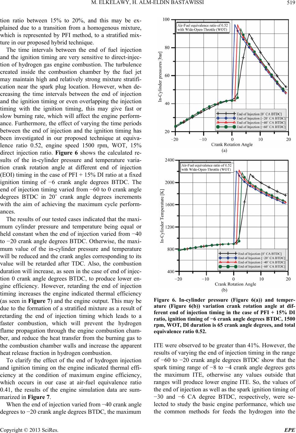 M. ELKELAWY, H. ALM-ELDIN BASTAWISSI Copyright © 2013 SciRes. EPE 519 tion ratio between 15% to 20%, and this may be ex- plained due to a transition from a homogenous mixture, which is represented by PFI method, to a stratified mix- ture in our proposed hybrid technique. The time intervals between the end of fuel injection and the ignition timing are very sensitive to direct-injec- tion of hydrogen gas engine combustion. The turbulence created inside the combustion chamber by the fuel jet may maintain high and relatively strong mixture stratifi- cation near the spark plug location. However, when de- creasing the time intervals between the end of injection and the ignition timing or even overlapping the injection timing with the ignition timing, this may give fast or slow burning rate, which will affect the engine perform- ance. Furthermore, the effect of varying the time periods between the end of injection and the ignition timing has been investigated in our proposed technique at equiva- lence ratio 0.52, engine speed 1500 rpm, WOT, 15% direct injection ratio. Figure 6 shows the calculated re- sults of the in-cylinder pressure and temperature varia- tion crank rotation angle at different end of injection (EOI) timing in the case of PFI + 15% DI ratio at a fixed ignition timing of −6 crank angle degrees BTDC. The end of injection timing varied from −60 to 0 crank angle degrees BTDC in 20˚ crank angle degrees increments with the aim of achieving the maximum cycle perform- ances. The results of our tested cases indicated that the maxi- mum cylinder pressure and temperature being equal or held constant when the end of injection varied from −40 to −20 crank angle degrees BTDC. Otherwise, the maxi- mum value of the in-cylinder pressure and temperature will be reduced and the crank angles corresponding to its value will be retarded after TDC. Also, the combustion duration will increase, as seen in the case of end of injec- tion 0 crank angle degrees BTDC, to produce lower en- gine efficiency. However, retarding the end of injection timing increases the engine indicated thermal efficiency (as seen in Figure 7) and the engine output. This may be due to the formation of a stratified mixture as a result of retarding the end of injection timing which leads to a faster combustion, which will prevent the hydrogen flame propagation through the engine combustion cham- ber, and reduce the heat transfer from the burning gas to the combustion chamber walls and increase the apparent heat release fraction in hydrogen combustion. To clarify the effect of the end of hydrogen injection and ignition timing on the engine indicated thermal effi- ciency at the condition of maximum engine efficiency, which occurs in our case at air-fuel equivalence ratio 0.41, the results of the engine simulation data are sum- marized in Figure 7. When the end of injection varied from −40 crank angle degrees to −20 crank angle degrees BTDC, the maximum (a) (b) Figure 6. In-cylinder pressure (Figure 6(a)) and temper- ature (Figure 6(b)) variation crank rotation angle at dif- ferent end of injection timing in the case of PFI + 15% DI ratio, ignition timing of −6 crank angle degrees BTDC, 1500 rpm, WOT, DI duration is 65 crank angle degrees, and total equivalence ratio 0.52. ITE were observed to be greater than 41%. However, the results of varying the end of injection timing in the range of −60 to −20 crank angle degrees BTDC show that the spark timing range of −8 to −4 crank angle degrees gets the maximum ITE, otherwise any values outside that ranges will produce lower engine ITE. So, the values of the end of injection as well as the spark ignition timing of −30 and −6 CA degree BTDC, respectively, were se- lected to study the basic engine performance, which use the common methods for feeds the hydrogen into the 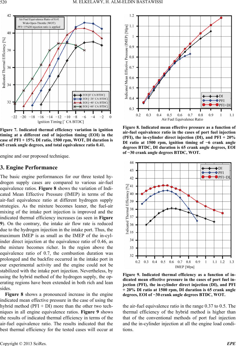 M. ELKELAWY, H. ALM-ELDIN BASTAWISSI Copyright © 2013 SciRes. EPE 520 Figure 7. Indicated thermal efficiency variation in ignition timing at a different end of injection timing (EOI) in the case of PFI + 15% DI ratio, 1500 rpm, WOT, DI duration is 65 crank angle degrees, and total equivalence ratio 0.41. engine and our proposed technique. 3. Engine Performance The basic engine performances for our three tested hy- drogen supply cases are compared to various air-fuel equivalence ratios. Figure 8 shows the variation of Indi- cated Mean Effective Pressure (IMEP) in terms of the air-fuel equivalence ratio at different hydrogen supply strategies. As the mixture becomes leaner, the fuel-air mixing of the intake port injection is improved and the indicated thermal efficiency increases (as seen in Figure 9). On the contrary, the intake air flow rate is reduced due to the hydrogen injection in the intake port. Thus, the maximum IMEP is as small as the IMEP of the in-cyl- inder direct injection at the equivalence ratio of 0.46, as the mixture becomes richer. In the region above the equivalence ratio of 0.7, the combustion duration was prolonged and the backfire occurred in the intake port in our experimental activity and the engine could not be stabilized with the intake port injection. Nevertheless, by using the hybrid method of the hydrogen supply, the op- erating regions have been extended in both rich and lean sides. Figure 8 shows a pronounced increase in the engine indicated mean effective pressure in the case of using the hybrid method (PFI + DI) more than the other two tech- niques in all engine equivalence ratios. Figure 9 shows the results of indicated thermal efficiency in terms of the air-fuel equivalence ratio. The results indicated that the best thermal efficiency for the tested cases will occur at Figure 8. Indicated mean effective pressure as a function of air-fuel equivalence ratio in the cases of port fuel injection (PFI), the in-cylinder direct injection (DI), and PFI + 20% DI ratio at 1500 rpm, ignition timing of −6 crank angle degrees BTDC, DI duration is 65 crank angle degrees, EOI of −30 crank angle degrees BTDC, WOT. Figure 9. Indicated thermal efficiency as a function of in- dicated mean effective pressure in the cases of port fuel in- jection (PFI), the in-cylinder direct injection (DI), and PFI + 20% DI ratio at 1500 rpm, DI duration is 65 crank angle degrees, EOI of −30 crank angle degrees BTDC, WOT. the air-fuel equivalence ratio in the range 0.37 to 0.5. The thermal efficiency of the hybrid method is higher than that of the conventional methods of port fuel injection and the in-cylinder injection at all the engine load condi- tions. 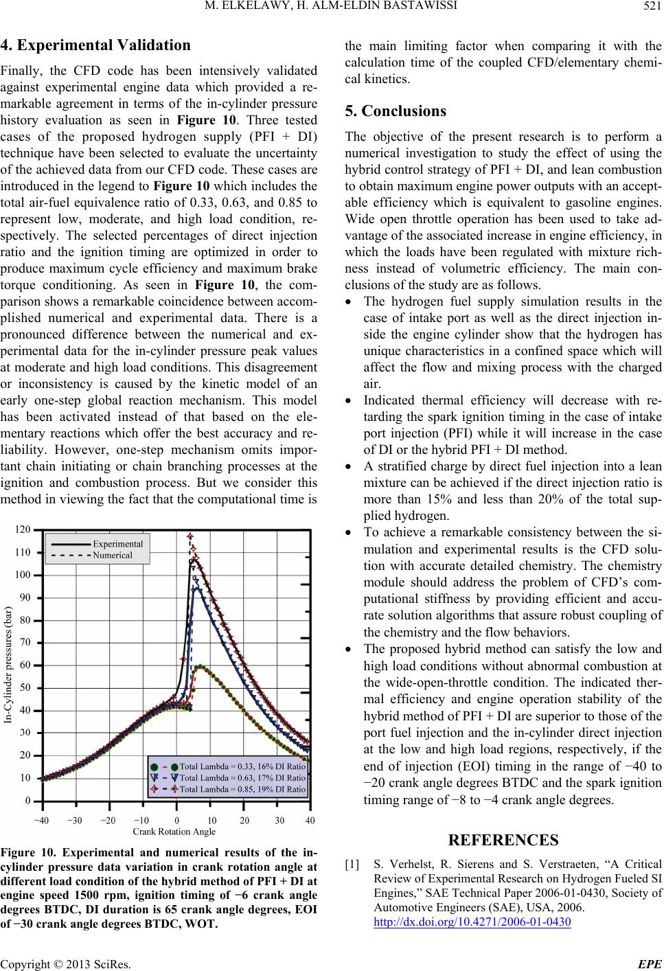 M. ELKELAWY, H. ALM-ELDIN BASTAWISSI Copyright © 2013 SciRes. EPE 521 4. Experimental Validation Finally, the CFD code has been intensively validated against experimental engine data which provided a re- markable agreement in terms of the in-cylinder pressure history evaluation as seen in Figure 10. Three tested cases of the proposed hydrogen supply (PFI + DI) technique have been selected to evaluate the uncertainty of the achieved data from our CFD code. These cases are introduced in the legend to Figure 10 which includes the total air-fuel equivalence ratio of 0.33, 0.63, and 0.85 to represent low, moderate, and high load condition, re- spectively. The selected percentages of direct injection ratio and the ignition timing are optimized in order to produce maximum cycle efficiency and maximum brake torque conditioning. As seen in Figure 10, the com- parison shows a remarkable coincidence between accom- plished numerical and experimental data. There is a pronounced difference between the numerical and ex- perimental data for the in-cylinder pressure peak values at moderate and high load conditions. This disagreement or inconsistency is caused by the kinetic model of an early one-step global reaction mechanism. This model has been activated instead of that based on the ele- mentary reactions which offer the best accuracy and re- liability. However, one-step mechanism omits impor- tant chain initiating or chain branching processes at the ignition and combustion process. But we consider this method in viewing the fact that the computational time is Figure 10. Experimental and numerical results of the in- cylinder pressure data variation in crank rotation angle at different load condition of the hybrid method of PFI + DI at engine speed 1500 rpm, ignition timing of −6 crank angle degrees BTDC, DI duration is 65 crank angle degrees, EOI of −30 crank angle degrees BTDC, WOT. the main limiting factor when comparing it with the calculation time of the coupled CFD/elementary chemi- cal kinetics. 5. Conclusions The objective of the present research is to perform a numerical investigation to study the effect of using the hybrid control strategy of PFI + DI, and lean combustion to obtain maximum engine power outputs with an accept- able efficiency which is equivalent to gasoline engines. Wide open throttle operation has been used to take ad- vantage of the associated increase in engine efficiency, in which the loads have been regulated with mixture rich- ness instead of volumetric efficiency. The main con- clusions of the study are as follows. The hydrogen fuel supply simulation results in the case of intake port as well as the direct injection in- side the engine cylinder show that the hydrogen has unique characteristics in a confined space which will affect the flow and mixing process with the charged air. Indicated thermal efficiency will decrease with re- tarding the spark ignition timing in the case of intake port injection (PFI) while it will increase in the case of DI or the hybrid PFI + DI method. A stratified charge by direct fuel injection into a lean mixture can be achieved if the direct injection ratio is more than 15% and less than 20% of the total sup- plied hydrogen. To achieve a remarkable consistency between the si- mulation and experimental results is the CFD solu- tion with accurate detailed chemistry. The chemistry module should address the problem of CFD’s com- putational stiffness by providing efficient and accu- rate solution algorithms that assure robust coupling of the chemistry and the flow behaviors. The proposed hybrid method can satisfy the low and high load conditions without abnormal combustion at the wide-open-throttle condition. The indicated ther- mal efficiency and engine operation stability of the hybrid method of PFI + DI are superior to those of the port fuel injection and the in-cylinder direct injection at the low and high load regions, respectively, if the end of injection (EOI) timing in the range of −40 to −20 crank angle degrees BTDC and the spark ignition timing range of −8 to −4 crank angle degrees. REFERENCES [1] S. Verhelst, R. Sierens and S. Verstraeten, “A Critical Review of Experimental Research on Hydrogen Fueled SI Engines,” SAE Technical Paper 2006-01-0430, Society of Automotive Engineers (SAE), USA, 2006. http://dx.doi.org/10.4271/2006-01-0430  M. ELKELAWY, H. ALM-ELDIN BASTAWISSI Copyright © 2013 SciRes. EPE 522 [2] M. K. Mahesh, Neelu, C. Prakash and G. Viswanathan, “Review of Fuel Induction Technologies for Automotive Hydrogen Propulsion,” SAE Technical Paper 2005-26- 350, Society of Automotive Engineers (SAE), USA, 2005. http://dx.doi.org/10.4271/2005-26-350 [3] A. M. Nande, T. Wallner and J. Naber, “Influence of Water Injection on Performance and Emissions of a Di- rect-Injection Hydrogen Research Engine,” SAE Techni- cal Paper 2008-01-2377, Society of Automotive Engin- eers (SAE), USA, 2008. http://dx.doi.org/10.4271/2008-01-2377 [4] J. R. Smith, S. Aceves and P. Van Blarigan, “Series Hy- brid Vehicles and Optimized Hydrogen Engine Design,” SAE Technical Paper 951955, Society of Automotive En- gineers (SAE), USA, 1995. http://dx.doi.org/10.4271/951955 [5] H. S. Yi, K. Min and E. S. Kim, “The Optimised Mixture Formation for Hydrogen Fuelled Engines,” International Journal of Hydrogen Energy, Vol. 25, No. 7, 2000, pp. 685-690. http://dx.doi.org/10.1016/S0360-3199(99)00082-8 [6] D. Messner, A. Wimmer, U. Gerke and F. Gerbig, “Ap- plication and Validation of the 3D CFD Method for a Hydrogen Fueled IC Engine with Internal Mixture For- mation,” SAE Technical Paper 2006-01-0448, Society of Automotive Engineers (SAE), USA, 2006. http://dx.doi.org/10.4271/2006-01-0448 [7] A. Wimmer, T. Wallner, J. Ringler and F. Gerbig, “H2- Direct Injection—A Highly Promising Combustion Con- cept,” SAE Technical Paper 2005-01-0108, Society of Automotive Engineers (SAE), USA, 2005. http://dx.doi.org/10.4271/2005-01-0108 [8] H. Rottengruber, M. Berckmüller, G. Elsässer, N. Brehm, et al., “Direct-Injection Hydrogen SI-Engine—Operation Strategy and Power Density Potentials,” SAE Technical Paper 2004-01-2927, Society of Automotive Engineers (SAE), USA, 2004. http://dx.doi.org/10.4271/2004-01-2927 [9] H. Rottengruber, et al., “A High-Efficient Combustion Con- cept for Direct Injection Hydrogen Internal Combustion Engine,” 15th World Hydrogen Energy Conference, Yo- kohama, 27 June-2 July 2004. [10] W. Peschka and W. Escher, “Germany’s Contribution to the Demonstrated Technical Feasibility of the Liquid- Hydrogen Fueled Passenger Automobile,” SAE Technical Paper 931812, Society of Automotive Engineers (SAE), USA, 1993. http://dx.doi.org/10.4271/931812 [11] S. Verhelst and T. Wallner, “Hydrogen-Fueled Internal Com- bustion Engines,” Progress in Energy and Combustion Science, Vol. 35, No. 6, 2009, pp. 490-527. http://dx.doi.org/10.1016/j.pecs.2009.08.001 [12] S. Toshio, “Improving Thermal Efficiency by Reducing Cooling Losses in Hydrogen Combustion Engines,” In- ternational Journal of Hydrogen Energy, Vol. 32, No. 17, 2007, pp. 4285-4293. http://dx.doi.org/10.1016/j.ijhydene.2007.06.002 [13] A. A. Amsden, P. J. O’Rourke and T. D. Butler, “KIVA- II: A Computer Program for Chemically Reactive Flows with Sprays,” Los Alamos National Laboratory Report 1989. [14] A. A. Amsden, “KIVA-3V: A Block-Structured KIVA Pro- gram for Engines with Vertical or Canted Valves,” Los Alamos National Laboratory Report, 1997. [15] Orbital Engine Company (Australia) Pty Ltd, “Orbital Project: UTP001. OCP UTP Single Cylinder Research En- gine,” Orbital Engine Company, Australia, 2004.
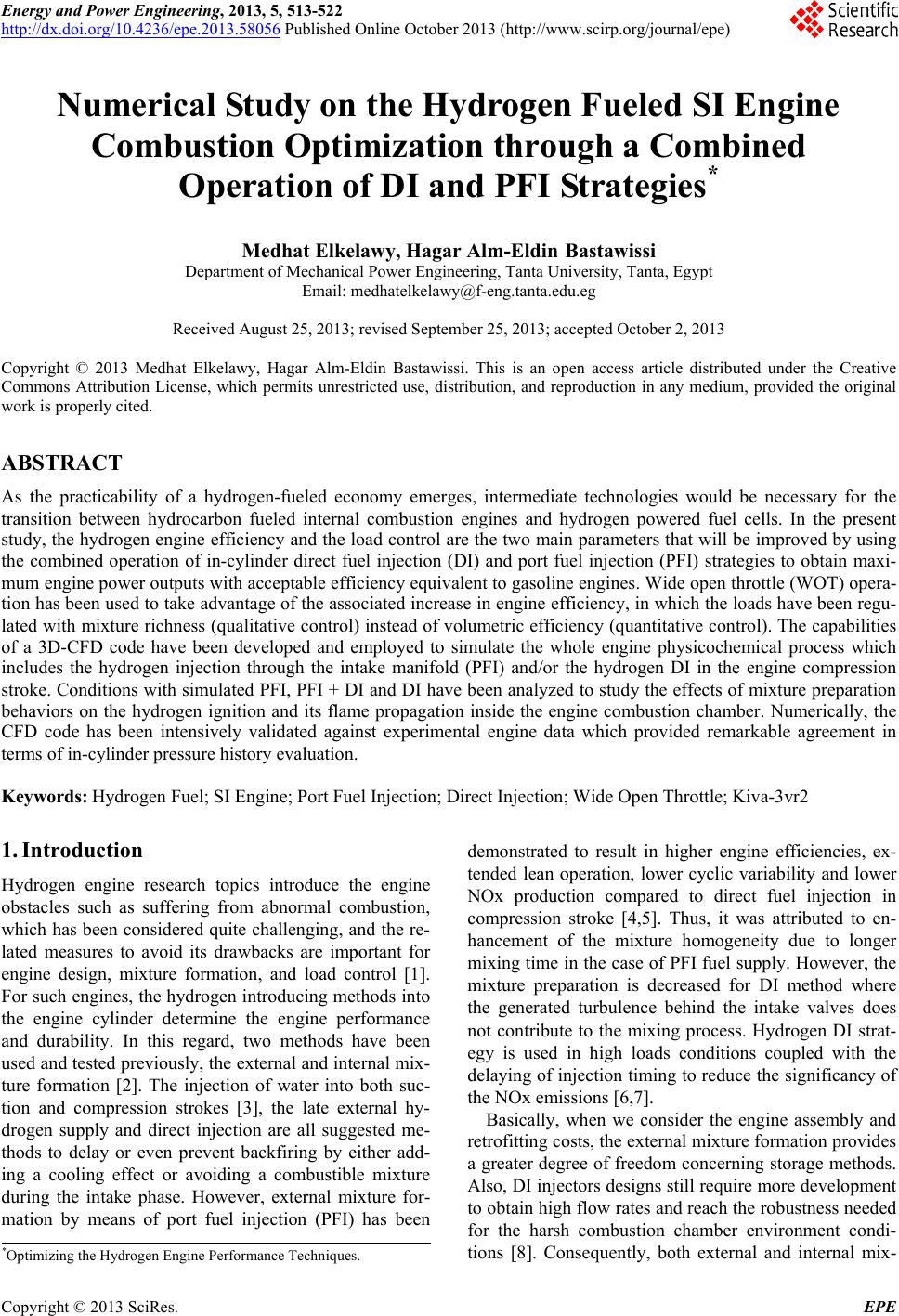
|