Journal of Software Engineering and Applications, 2013, 6, 49-55
doi:10.4236/jsea.2013.2013.67B009 Published Online July 2013 (http://www.scirp.org/journal/jsea)
Kinematic Motion Analysis and Structural Analysis of
Bellcrank Structures Using FEM
Byeong-Sam Kim1, Kyoungwoo Park2
1Department of Automotive engineering, Hoseo University, Asan-City, Korea; 2Department of Mechanical engineering, Hoseo Uni-
versity, Asan-City, Korea.
Email: kbs@hoseo.edu
Received June, 2013
ABSTRACT
The results of kinematic motion analysis were used for the structural analysis based on data that the load applied to each
part. The problem of the fatigue strength estimation of materials or components containing natural defects, inclusions or
in homogeneities is of great importance for both a scientifically or industrial point of view. Fatigue behavior in com-
ponents is often affected by the presence of residual stresses introduced by processes such as actuator system. Analysis
can provide the estimation of the crack growth curves with sufficient accuracy, even in case of complicated bell crank
structures which are crucial for preserving aileron integrity and which participate in transfer of load. Probability of
crack detection or any other damage detection is a result of many factors. An endurance life prediction of bell crank is
used finite element analyses. Endurance test data for slim test specimens were compared with the predicted fatigue life
for verification.
Keywords: Kinematic Motion Analysis; Fatigue Life Analysis; FEM; Bell Crank System; Structural Analysis
1. Introduction
The share of air flight control device wing aileron,
elevator, rudder control of the main control device (Pri-
mary control system) and secondary day personal flap,
spoiler, leading edge flap control of a secondary control
device (Secondary control system), they are divided into
domestic demand, despite the abundance of technology
received recognition in the civil aircraft market, has not
been adopted. Medium-class business jet existing parts of
the aircraft wing flaps protruding actuators have been
called for air resistance and fuel economy. In this study,
the protruding parts of an aircraft wing flaps actuators
(aileron actuator) mounted inside the wing to remove the
protruding part, and the resulting increase in air re-
sistance and fuel economy were targeted. In this study,
the wings are mounted inside the actuator system in order
to meet the requirements for the design and kinematic
analysis of aileron (kinematic motion system) and struc-
tural analysis to ensure the structural safety through the
analysis results are presented. Kinematic motion analysis
program by Sim Designer acting on each joint of aileron
force and torque aileron requirements for information
corresponding to the conditions that were identified,
based to identify the characteristics of each part and the
structural basis of this analysis using ABAQUS 6.5
model was developed separately by each working on
structural analysis, structural characteristics and per-
formance and forecasts were performed. In addition,
components of the safety margin for hydraulic compo-
nents were confirmed by checking the structural safety.
2. Kinematic Motion Analysis
2.1. Fatigue Prediction Analysis
The static and cyclic stress-strain curves are modified by
the local plastic strain as a effect of material hardening.
Specifically, analytical expressions to describe material
behavior have been adapted for the implementation into
the software FEMFAT v4.6 where local SN-curves are
used for linear damage accumulation according Palm-
gren-Miner’s rule. The estimate the simulation number of
cycles, We used FEMFAT v4.6 with a high diagram
–admissible amplitude by given mean for high cycle fa-
tigue with bending influence relative stress gradient
(bending χ' = 2/b).

1
1
2
altben altTC
genDurance
fb

 (1)
The construction of High diagram calculates the fa-
tigue life of a part under constant amplitude oscillatory
loading assuming the stress range controls fatigue life.
The Stress-Life method is the Wohler, or S-N diagram,
Copyright © 2013 SciRes. JSEA
Kinematic Motion Analysis and Structural Analysis of Bellcrank Structures Using FEM
50
where a suitable structural stress, S (or strain or stress
intensity factor) shown schematically for two materials
[1]. The S-N diagram plots nominal stress amplitude S
versus cycles to failure N. Rainflow cycle counting is
used together with Palmgren-Miner’s accumulated dam-
age rule to process variable amplitude loading. In this
model it is assumed that the damage on the structures per
load cycle is constant at a given stress range and equal.
The total damage accumulated during N cycles of ampli-
tude is given by:
i
a
S
1n
0
i
i
d
where, 1
a
.i
b
i
s
S
K
(2)
or
1
1nS
d
0i
b
a
i
s
d
K
(3)
The accumulated damage
is independent of the
sequence in which stress will occur. According to Min-
er’s rule, fatigue failure occurs if total damage i
a >
S
d
, where d
is the critical cumulative damage,
which is often taken as 1. Letting i
a=S d
, the basic
damage expression of equation can be expresses in terms
of time to failure [2].
2.2. Mechanism System
In the generic fighter of aileron example discussed in this
paper, linear models will be used. This is not a requisite,
but for the analysis based on non-linear models, more
detailed information and motion algorithm. The linear
actuators of mechanism can be either hydraulic rams or
electric spindle devices. The aileron actuator motion-
bases generally utilize a mechanism known’s as the
Stwart Platform or “hexapod”, which was originally
proposed for a base-frame, six actuator legs (the jacks).
This method can be applied to both the gravitational
forces and the aerodynamic load and gravitational forces
categories [3]. The positioning of the links and joints are
not changed within the analysis, because of the nature of
the design synthesis performed on the mechanism. By
changing the lengths of members or moving the links or
joints, the desired motion for morphing the wing may no
longer be achievable. Aileron’s system as shown in the
3D model is composed of the larger piston, bell crank,
clevis, stroke and flap in Figure 1. By using kinematic
motion system analysis, all of the above free design
variable and constraints can be combined to yield the
most architecture aileron actuator of the four major parts.
This is part of joint connecting the four joint. For simpli-
fied system analysis, in this point unnecessary pin were
also removed. This method can be applied to both the
gravitational forces and the aerodynamic load and gravi-
tational forces categories for aileron mechanism in Fig-
ure 2.
Aileron mechanism have moved up the wing when the
maximum angle of 1(TEU 19°), went down to be-
low 11° (TED 11°) at Case1 and when the wings
moved up 24° (TEU 24°), went down to below 16°
(TED 16°) Case 2 a time were compared. The rated
pressure of the pressure piston (rated pressure) 2775 psi,
the maximum pressure 3000 psi applied when compared
in each case. The motion analysis represented a Sim De-
sign@ and, Adams@, program. See Table 1.
2.3. Structural Analysis
The structural analysis model can be divided into three.
The piston rod, bellcrank, stroke is these three different
parts. The results of kinematic motion analysis were used
for the structural analysis based on data that the load ap-
plied to each part. The static pressure range because it
Figure 1. Aircraft control system movement.
Table 1. Kinematic motion analysis in each case.
Case Aileron Angle Pressure (psi)
2775
TEU 19°
3000
2775
Case1
TED 11°
3000
2775
TEU 24° 3000
2775
Case2
TED 16°
3000
Copyright © 2013 SciRes. JSEA
Kinematic Motion Analysis and Structural Analysis of Bellcrank Structures Using FEM 51
Figure 2. Connection composition and joint mechanism.
contains the maximum pressure in the range of a maxi-
mum pressure of 3000 psi was the result of applying the
data. Case 1 in Table 2 and Case 2 in Table 3 also occurs
in the value of the force and torque limit value because
they are included within the scope of Case 2 is a TEU 24
°TED 16°and in the context of structural analysis was
carried out. The pressure of piston can be used the
maximum pressure 3000 psi. Each model defines a mate-
rial density as well as linear, elastic isotropic values of
modulus of elasticity, and Poisson’s ratio. As with the
real constants sets, the first tentative designs are modeled
after the second generation model [4, 5]. The materials
property include stainless steel (AMS5862 15-5PH) was
applied, element type the Tetra mesh (C3D4) were used
for ABAQUS 5.7@.
3. Results of FE Analysis
3.1. Results of FE Structural Analysis
Table 3 shows the result of FE analysis in each part. The
results of margin of safety for bell crank (TED 16°) and
(TED 24°) with this final design are 0.434 and 0.429
when the load is estimated to be insufficient to withstand
in Figure 3. Bell crank joint connection with the piston
rod in the most stress and displacement results showed
values of the angle did not differ significantly [6]. The
stroke is associated with the bell crank joint was the most
stress and displacement. However, the resulting values
were different angle, TEU 24°at a TED 16°greater
than the stress and displacement angles seen representing
the larger part that the recipient can know the load is
greater in Figure 4 of piston, and Figure 5 of stroke.
Table 2. The results of kinematic motion analysis in case 1.
TED 11° TEU 19°
Joint Pressure
(psi) Force
(N)
Torque
(in-lb)
Force
(N)
Torque
(in-lb)
2775 37936 2929.2 379362929.2
Piston &
Bell crank 3000 41012 3166.8 410123166.8
Bell crank
& Clevis 2775 54983 8222.8 67412 11340.4
Table 3. The results of kinematic motion analysis in case 2.
TED 16° TEU 24°
Joint Pressure
(psi) Force
(N)
Torque
(in-lb)
Force
(N) Torque (in-lb)
2775 379362929.2 37936 2929.2
Piston &
Bell crank3000 410123166.8 41012 3166.8
2775 569798497.3 79347 14713.8
Bell crank
& Clevis3000 616009186.8 85781 15907.1
2775 394733269.7 61413 5081.8
Bell crank
& Stroke3000 426743534.9 66392 5493.8
2775 394733031.2 61413 4717.5
Stroke &
Flap 3000 426743094.4 66392 5100.0
The stroke, but also belong within the range of margin of
safety is sufficient to withstand the loads are evaluated.
When applied to the piston displacement amount 3000
Copyright © 2013 SciRes. JSEA
Kinematic Motion Analysis and Structural Analysis of Bellcrank Structures Using FEM
52
psi maximum pressure 0.105 mm, Von-Mises Stresses
274.6 Mpa 2.446 calculated by the margin of safety is
sufficient to withstand the loads are evaluated [7,8].
3.2. Results of Fatigue Analysis
By a standard fatigue life analysis with FEMFAT the
following influences are considered: Influence of the
relative stress gradient to consider notch support effects -
Mean stress influence Modification of high diagram by
calculating a notch ultimate strength statistic influence.
The calculation for the fatigue life presented in this para-
graph deviates in some important aspects from standard
calculations for fatigue life. Prior to the fatigue analysis a
forming simulation with FEMFAT v4.6 has
been made [9]. The results of this simulation have been
mapped onto a new mesh better suitable for a structural
analysis in Figure 6. The structural analysis delivers the
additional stresses of each load cycle. Therefore follow-
ing data is included additional to a standard calculation in
the model. The second point needs special attention here
because the residual stresses are very high. Usually it is
assumed that the high stresses resulting from manufac-
turing are somehow relieved in the first load cycles.
However, such an effect cannot be simulated with a pro-
gram on the basis of continuum mechanics in Figure 7.
TED16°
Max. Stress Displacement
(a)
TEU 24°
Max. Stress Displacement
(b)
Figure 3. FE Analysis of aileron bellcrank in TED 16°and bellcrank in TED 24°
Copyright © 2013 SciRes. JSEA
Kinematic Motion Analysis and Structural Analysis of Bellcrank Structures Using FEM 53
TED16°
Max. Stress Displacement
Figure 4. FE Analysis of piston in TED 16°.
Max. Stress Displacement
Figure 5. FE Analysis of Stroke in TED 24°
Copyright © 2013 SciRes. JSEA
Kinematic Motion Analysis and Structural Analysis of Bellcrank Structures Using FEM
Copyright © 2013 SciRes. JSEA
54
Figure 6. Haigh diagram of stroke in TED 24
Table 4. Results of FE Fatigue analysis.
Pressure (psi) Angle Mean.
Stress (Mpa)
Margin of
Safety (N.S.)
Max.
Displacement (mm)
16° 659.8 0.434 0.253
Bell crank 3000
24° 662.1 0.429 0.256
16° 443.6 1.133 0.796
Stroke 3000
24° 620.1 0.527 0.923
Piston 3000 274.6 2.446 0.105
(a) (b)
Figure 7. Results of fatigue analysis of stroke and bell crank (a) After results of fatigue analysis of bell crank (b) After results
of fatigue analysis of stroke.
To account for this effect precisely further measure-
ments are necessary, here the mean stresses have been
halved. Inclusion of the plastic equivalent strain accord-
ing Masendorf shows a clear influence on the results:
without it the computed fatigue life is 1,44 million load
cycles, with it 1.752 million load cycles.
This research to improve the endurance life of stroke
required for the life cycle design, analysis and testing for
the integration of these technologies and secure source
technology to derive prototype has been applied, the fol-
lowing were able to obtain useful results. The FE results,
designed and built by the stroke was able to reduce the
time and cost. The endurance life cycle how to establish
durable, and is designed to help improve productivity,
and to be tested.
Therefore the fatigue life calculated is lower than the
fatigue life measured. By generation of new materials for
different plastic equivalent strains according to the mate-
rial’s property the fatigue life result can be improved once
again. See Table 4.
Kinematic Motion Analysis and Structural Analysis of Bellcrank Structures Using FEM 55
4. Conclusions and Discussion
In this paper, FE structural analysis and Fatigue pre-
diction analysis of the flight control actuators for capa-
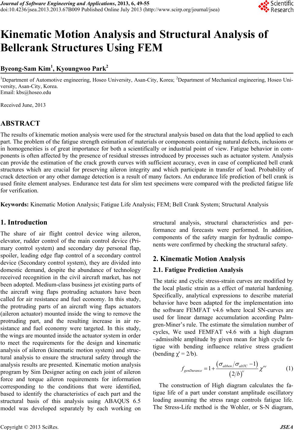
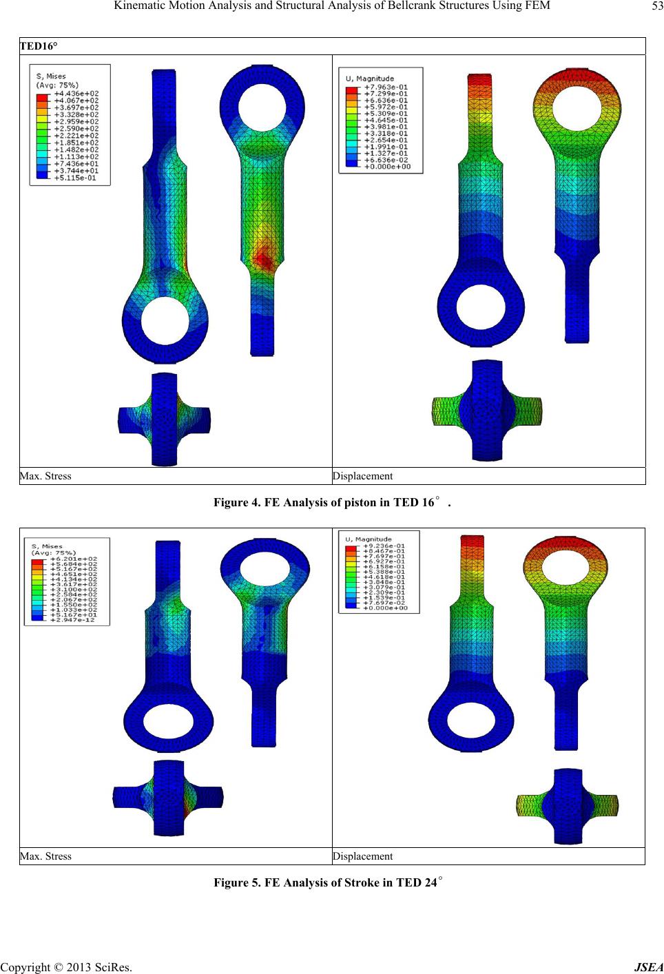
city are presented. Aileron actuator 3 main parts of the
piston, bell crank, divided by the stroke of 3D analysis
model was developed. Verification calculations prove the
model developed in Sim Design and ABAQUS 5.7 and
FEMFAT 4.6 as being accurate. FE structural analysis
and Fatigue prediction analysis performed on the basis of
stress distribution and the amount of displacement could
be predicted. Analysis of aileron actuator model experi-
ments and simulations to create the actual equipment that
would reduce costs and time are considered. In addition,
through the optimization of the analytical model analysis
time and results can be predicted more accurately than is
believed to be Through comparison of the test results and
analysis, aileron actuator of the results for the endurance
can secure the trust stroke, piston, bell crank, depth due
to the number of design guidelines to provide for the en-
durance in life expectancy. By including the results from
process simulations, significant improvements regarding
correlation of fatigue life predictions to test results can be
achieved. Among the biggest effects are influences from
material. Methods and interfaces have been implemented
in FEMFAT to account for the manufacturing influences.
Benefits from applying these new features are high at
reasonable efforts because results from process simula-
tion are usually available during concurrent engineering.
5. Acknowledgment
This research was supported by the Korea Institute for
Advancement of Technology, supporting fund of Honam
Leading Industry Office in 2013 by grant No. 2013-0114.
REFERENCES
[1] B. S. Kim et al., “A Numerical Analysis of the Dimen-
sional Stability of the Plastic Composites Using a Ther-
moviscoelastic Composite Using a Thermoviscoelastic,”
Journal of Composite Material, Vol. 36, No. 20, 2002, pp.
2389-2403. doi:10.1177/0021998302036020882
[2] B. S. Kim et al., “Dimensional Stability Analysis of
Themoviscoelastic for EMI Shielding Using Mela-
mine-Formaldehyde Composite Materials,” Int's Confer-
ence on Advances in Structural Engineering and Me-
chanics (ASEM02), 2002.
[3] T. K. Ahn and C. D. Mote Jr., “Monitoring and Prevent-
ing the Kick-off during Cutting,” California Cedar Prod-
uct Co., 1996.
[4] M. K. Choi and E. K. Kim, “Ultra-Thinned Si Wafer
Processing for Wafer Level 3D Packaging,” Journal of
KWJS, Vol. 26, No. 1, 2008, pp. 12-16.
[5] S. A. Nasar, “Linear Electric Motors: Theory, Design,
and Pratical Applications,” 2008, Prentice-Hall. Inc.
[6] P. C. Sen, “On Linear Synchronous Motor (LSM) for
High Speed Propulsion,” IEEE Transaction on Magnetics,
Vol. Mag-11, No. 5, 1975, pp. 1484-1486.
doi:10.1109/TMAG.1975.1058873
[7] C. W. Jun, K.Y. Park and Q. S. Kang, “On the Static
Test of Aileron Control System for a Basic Trainer,”
KSAS journal, Vol. 28, No. 3, 2000, pp. 150-155.
[8] S. S. Kim, Y. J. Kang and K. I. Lee, “Experimental Veri-
fication of Flexible Multibody Dynamic Simulations for
A Rotating Beam,” KSME International Journal, Vol. 26,
No. 2, 2002, pp. 267-274.
[9] I. H. Moon and Y. K. Huang, “Evaluation of a Wafer
Transportation Speed for Propulsion Nozzle Array on Air
Levitation System,” Journal of Mechanical Science and
Technology (KSME Int. J.), Vol. 20, No. 9, 2006, pp.
1492-1501.
Copyright © 2013 SciRes. JSEA