Paper Menu >>
Journal Menu >>
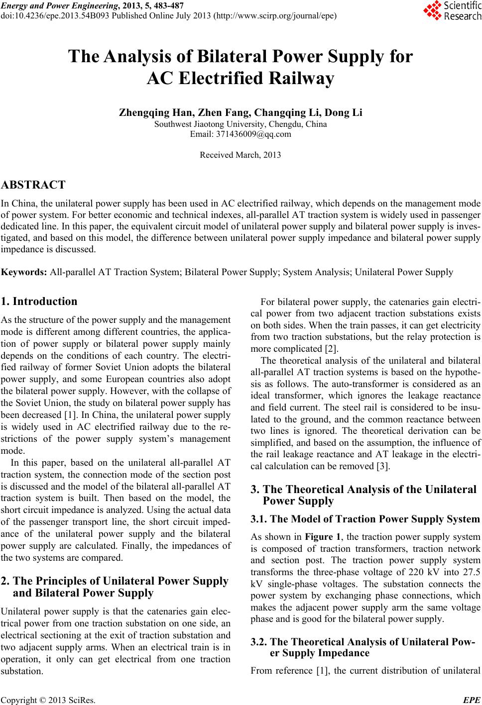 Energy and Power Engineering, 2013, 5, 483-487 doi:10.4236/epe.2013.54B093 Published Online July 2013 (http://www.scirp.org/journal/epe) The Analysis of Bilateral Power Supply for AC Electrified Railway Zhengqing Han, Zhen Fang, Changqing Li, Dong Li Southwest Jiaotong University, Chengdu, China Email: 371436009@qq.com Received March, 2013 ABSTRACT In China, the unilateral power supply has been used in AC electrified railway, which depends on the management mode of power system. For better economic and technical indexes, all-parallel AT traction system is widely used in passenger dedicated line. In this paper, the equivalent circuit model of unilateral power supply and bilateral power supply is inves- tigated, and based on this model, the difference between unilateral power supply impedance and bilateral power supply impedance is discussed. Keywords: All-parallel AT Traction System; Bilateral Power Supply; System Analysis; Unilateral Power Supply 1. Introduction As the structure of the power supply and the management mode is different among different countries, the applica- tion of power supply or bilateral power supply mainly depends on the conditions of each country. The electri- fied railway of former Soviet Union adopts the bilateral power supply, and some European countries also adopt the bilateral power supply. However, with the collapse of the Soviet Union, the study on bilateral power supply has been decreased [1]. In China, the unilateral power supply is widely used in AC electrified railway due to the re- strictions of the power supply system’s management mode. In this paper, based on the unilateral all-parallel AT traction system, the connection mode of the section post is discussed and the model of the bilateral all-parallel AT traction system is built. Then based on the model, the short circuit impedance is analyzed. Using the actual data of the passenger transport line, the short circuit imped- ance of the unilateral power supply and the bilateral power supply are calculated. Finally, the impedances of the two systems are compared. 2. The Principles of Unilateral Power Supply and Bilateral Power Supply Unilateral power supply is that the catenaries gain elec- trical power from one traction substation on one side, an electrical sectioning at the exit of traction substation and two adjacent supply arms. When an electrical train is in operation, it only can get electrical from one traction substation. For bilateral power supply, the catenaries gain electri- cal power from two adjacent traction substations exists on both sides. When the train passes, it can get electricity from two traction substations, but the relay protection is more complicated [2]. The theoretical analysis of the unilateral and bilateral all-parallel AT traction systems is based on the hypothe- sis as follows. The auto-transformer is considered as an ideal transformer, which ignores the leakage reactance and field current. The steel rail is considered to be insu- lated to the ground, and the common reactance between two lines is ignored. The theoretical derivation can be simplified, and based on the assumption, the influence of the rail leakage reactance and AT leakage in the electri- cal calculation can be removed [3]. 3. The Theoretical Analysis of the Unilate ral Power Supply 3.1. The Model of Traction Power Supply System As shown in Figure 1, the traction power supply system is composed of traction transformers, traction network and section post. The traction power supply system transforms the three-phase voltage of 220 kV into 27.5 kV single-phase voltages. The substation connects the power system by exchanging phase connections, which makes the adjacent power supply arm the same voltage phase and is good for the bilateral power supply. 3.2. The Theoretical Analysis of Unilateral Pow- er Supply Impedance From reference [1], the current distribution of unilateral Copyright © 2013 SciRes. EPE 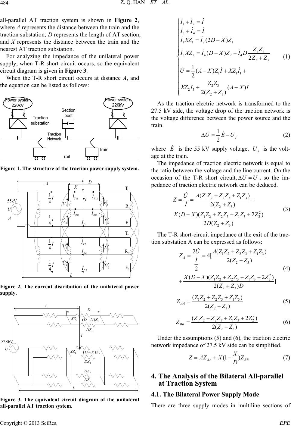 Z. Q. HAN ET AL. 484 all-parallel AT traction system is shown in Figure 2, where A represents the distance between the train and the traction substation; D represents the length of AT section; and X represents the distance between the train and the nearest AT traction substation. For analyzing the impedance of the unilateral power supply, when T-R short circuit occurs, so the equivalent circuit diagram is given in Figure 3. When the T-R short circuit occurs at distance A, and the equation can be listed as follows: Figure 1. The struct ur e of the traction power supply sy stem. 1 4 I 1 4I 1 4I 1 4I I A D X 11T I 12T I 11 R I 12 R I 1F I 2T I 2 R I 2 F I 1 T 1 R 1 F 2 T 2 R 2 F L U 55kV ' 1 U ' 2 U ' 1 U ' 2 U 1 U 2 U 1 U 2 U A Figure 2. The current distribution of the unilateral power supply. 2 D Z 3 DZ 3 DZ 2 () D XZ 2 X Z 1 DZ I 1 X Z 1 () D XZ D A L U 27.5kV Figure 3. The equivalent circuit diagram of the unilateral all-parallel AT traction system. 12 34 11 21 23 3242 4 2 111 23 23 23 (2 ) () 2 1() 2 () 2( ) II I II I IXZIDXZ 3 Z Z IXZI DXZID Z Z UAXZIXZI ZZ XZ IAXI ZZ (1) As the traction electric network is transformed to the 27.5 kV side, the voltage drop of the traction network is the voltage difference between the power source and the train. 1 2 j UEU (2) where is the 55 kV supply voltage, E j U is the volt- age at the train. The impedance of traction electric network is equal to the ratio between the voltage and the line current. On the occasion of the T-R short circuit,, so the im- pedance of traction electric network can be deduced. UU 1223 13 23 2 1223 132 23 () 2( ) ()( 2 2( ) AZZZZ ZZ U ZZZ I ) X DXZZZZZZZ DZ Z (3) The T-R short-circuit impedance at the exit of the trac- tion substation A can be expressed as follows: 1223 13 23 2 1223 132 23 () 24[ 2( ) 2 ()( 2 ] 2( ) A AZZ ZZZZ U ZZZI XDXZZZZZZZ ZZD ) (4) 1223 13 23 ( 2( ) AA ) Z ZZZZZ ZZZ (5) 2 1223 132 23 (2 2( ) BB ) Z ZZZZZ Z ZZZ (6) Under the assumptions (5) and (6), the traction electric network impedance of 27.5 kV side can be simplified. (1 ) AA BB X Z AZ XZ D (7) 4. The Analysis of the Bilateral All-parallel at Traction System 4.1. The Bilateral Power Supply Mode There are three supply modes in multiline sections of Copyright © 2013 SciRes. EPE 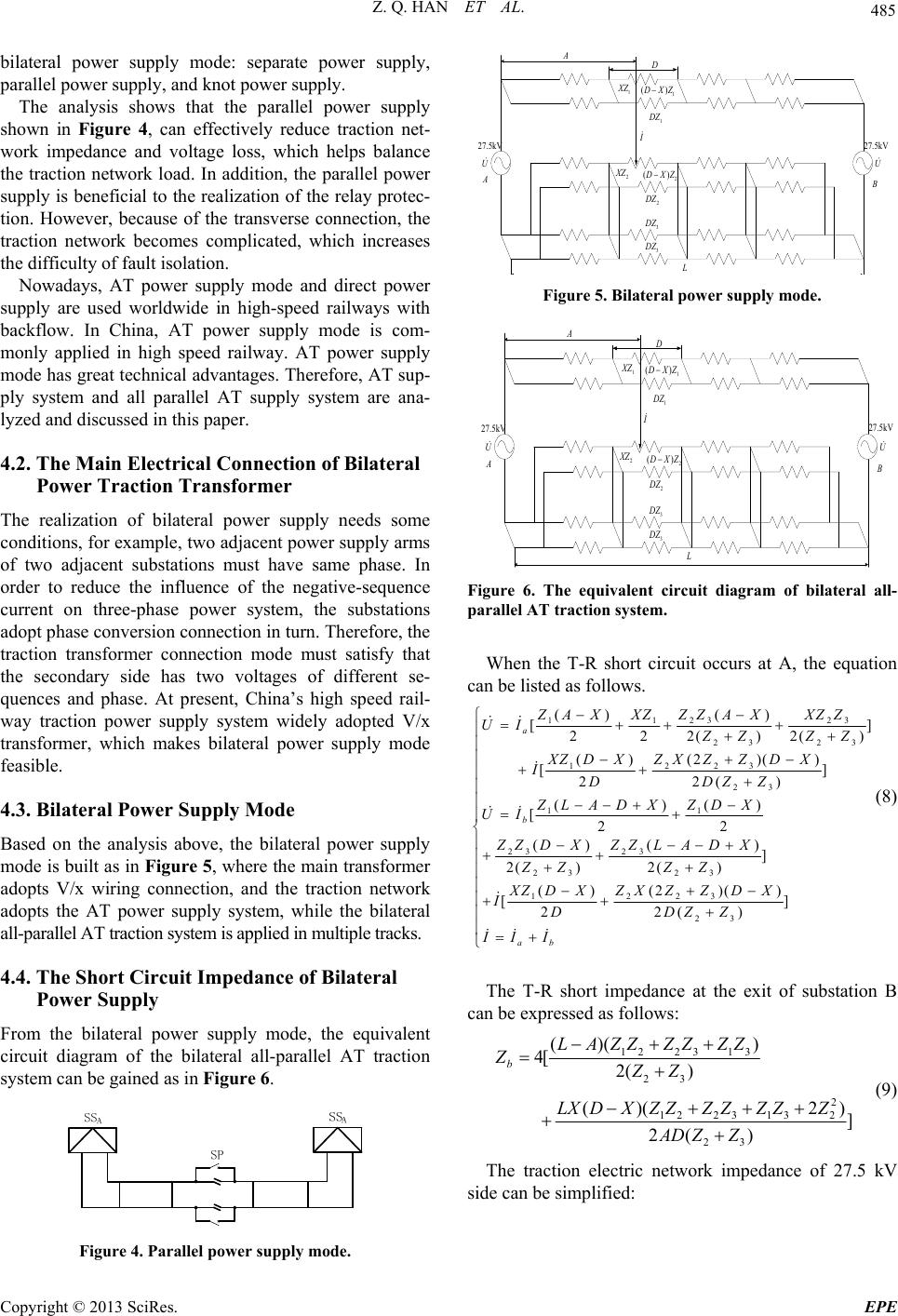 Z. Q. HAN ET AL. 485 bilateral power supply mode: separate power supply, parallel power supply, and knot power supply. The analysis shows that the parallel power supply shown in Figure 4, can effectively reduce traction net- work impedance and voltage loss, which helps balance the traction network load. In addition, the parallel power supply is beneficial to the realization of the relay protec- tion. However, because of the transverse connection, the traction network becomes complicated, which increases the difficulty of fault isolation. Nowadays, AT power supply mode and direct power supply are used worldwide in high-speed railways with backflow. In China, AT power supply mode is com- monly applied in high speed railway. AT power supply mode has great technical advantages. Therefore, AT sup- ply system and all parallel AT supply system are ana- lyzed and discussed in this paper. 4.2. The Main Electrical Connection of Bilateral Power Traction Transformer The realization of bilateral power supply needs some conditions, for example, two adjacent power supply arms of two adjacent substations must have same phase. In order to reduce the influence of the negative-sequence current on three-phase power system, the substations adopt phase conversion connection in turn. Therefore, the traction transformer connection mode must satisfy that the secondary side has two voltages of different se- quences and phase. At present, China’s high speed rail- way traction power supply system widely adopted V/x transformer, which makes bilateral power supply mode feasible. 4.3. Bilateral Power Supply Mode Based on the analysis above, the bilateral power supply mode is built as in Figure 5, where the main transformer adopts V/x wiring connection, and the traction network adopts the AT power supply system, while the bilateral all-parallel AT traction system is applied in multiple tracks. 4.4. The Short Circuit Impedance of Bilateral Power Supply From the bilateral power supply mode, the equivalent circuit diagram of the bilateral all-parallel AT traction system can be gained as in Figure 6. Figure 4. Parallel power supply mode. U 27.5kV A U 27.5kV B 2 D Z 3 D Z 3 D Z 2 () D XZ 2 XZ 1 D Z 1 XZ 1 () D XZ D A L I Figure 5. Bilateral power supply mode . U 27.5kV A U 27.5k V B 2 D Z 3 D Z 3 D Z 2 () D XZ 2 XZ 1 D Z 1 XZ 1 () D XZ D A L I Figure 6. The equivalent circuit diagram of bilateral all- parallel AT traction system. When the T-R short circuit occurs at A, the equation can be listed as follows. 23 23 11 23 23 223 1 23 11 23 23 23 23 223 1 () () [] 222()2( (2)( ) () [] 22() ()() [22 () () ] 2( )2( ) (2 )( () [2 a b ZZ A XXZZ ZA XXZ UI ) Z ZZZ ZX ZZD X XZ DX IDDZZ ZLA DXZDX UI ZZ DXZZ LADX ZZ ZZ ZXZZD X XZ DX ID 23 )] 2( ) ab DZ Z II I (8) The T-R short impedance at the exit of substation B can be expressed as follows: 1223 13 23 2 1223 132 23 ()( ) 4[ 2( ) ()( 2 ] 2( ) b LA ZZZZZZ ZZZ LXDXZZZZZZZ AD ZZ ) (9) The traction electric network impedance of 27.5 kV side can be simplified: Copyright © 2013 SciRes. EPE 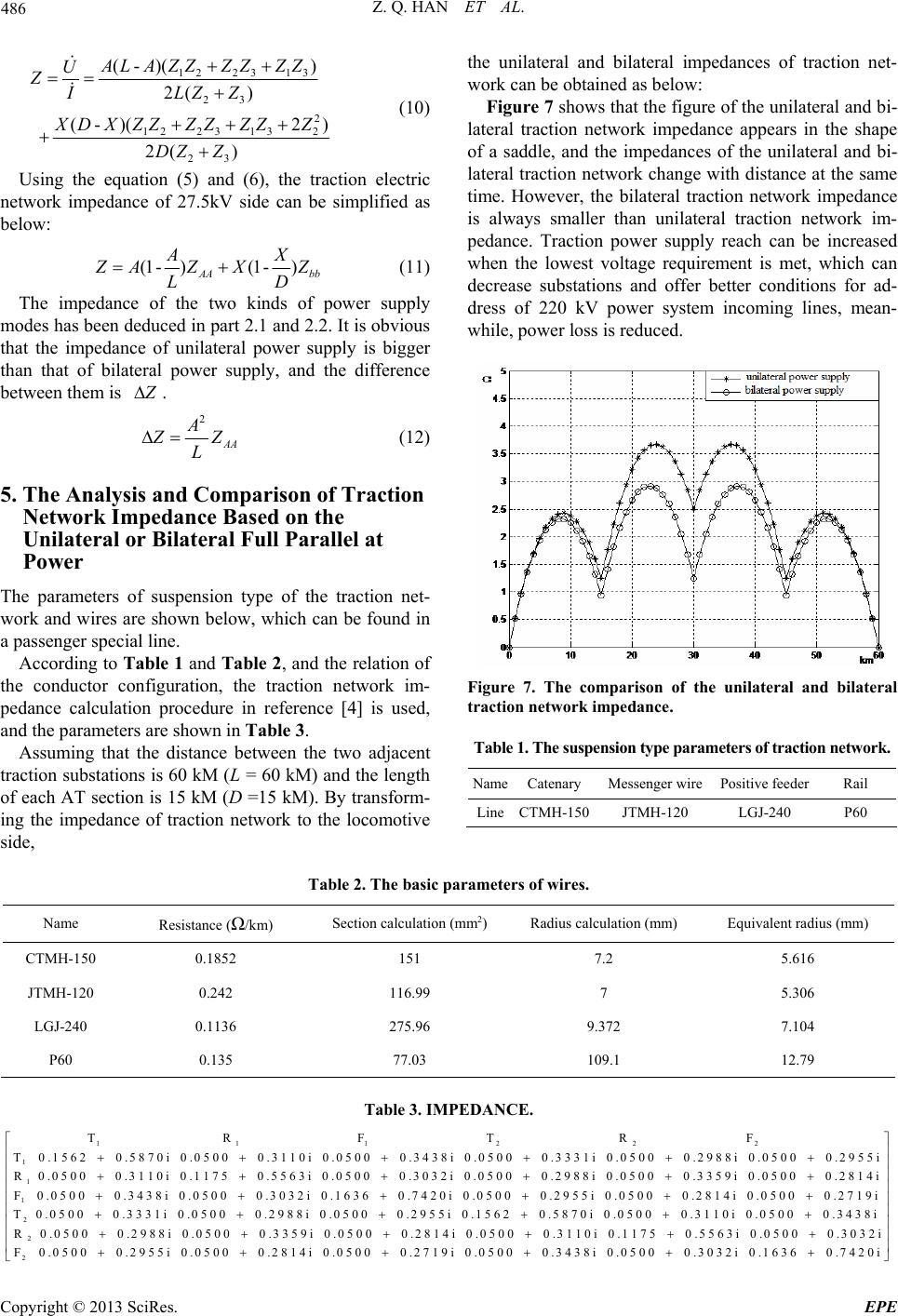 Z. Q. HAN ET AL. Copyright © 2013 SciRes. EPE 486 the unilateral and bilateral impedances of traction net- work can be obtained as below: 1223 13 23 2 1223 132 23 (-)( ) 2( ) (-)(2 ) 2( ) ALA ZZZZZZ U ZLZ Z I X D XZZZZZZZ DZ Z (10) Figure 7 shows that the figure of the unilateral and bi- lateral traction network impedance appears in the shape of a saddle, and the impedances of the unilateral and bi- lateral traction network change with distance at the same time. However, the bilateral traction network impedance is always smaller than unilateral traction network im- pedance. Traction power supply reach can be increased when the lowest voltage requirement is met, which can decrease substations and offer better conditions for ad- dress of 220 kV power system incoming lines, mean- while, power loss is reduced. Using the equation (5) and (6), the traction electric network impedance of 27.5kV side can be simplified as below: (1 -)(1 -) AA bb AX Z AZX Z LD (11) The impedance of the two kinds of power supply modes has been deduced in part 2.1 and 2.2. It is obvious that the impedance of unilateral power supply is bigger than that of bilateral power supply, and the difference between them is Z . 2 AA A Z Z L (12) 5. The Analysis and Comparison of Traction Network Impedance Based on the Unilateral or Bilateral Full Parallel at Power The parameters of suspension type of the traction net- work and wires are shown below, which can be found in a passenger special line. According to Table 1 and Tabl e 2, and the relation of the conductor configuration, the traction network im- pedance calculation procedure in reference [4] is used, and the parameters are shown in Table 3. Figure 7. The comparison of the unilateral and bilateral traction network impedanc e. Table 1. The suspension type parameters of traction network. Assuming that the distance between the two adjacent traction substations is 60 kM (L = 60 kM) and the length of each AT section is 15 kM (D =15 kM). By transform- ing the impedance of traction network to the locomotive side, NameCatenaryMessenger wire Positive feeder Rail LineCTMH-150JTMH-120 LGJ-240 P60 Table 2. The basic parameters of wires. Name Resistance (Ω/km) Section calculation (mm2) Radius calculation (mm) Equivalent radius (mm) CTMH-150 0.1852 151 7.2 5.616 JTMH-120 0.242 116.99 7 5.306 LGJ-240 0.1136 275.96 9.372 7.104 P60 0.135 77.03 109.1 12.79 Table 3. IMPEDANCE. 111222 1 T R F T R F T 0.1562 0.5870i 0.0500 0.3110i 0.0500 1 1 0.3438i 0.0500 0.3331i 0.0500 0.2988i 0.0500 0.2955i R 0.0500 0.3110i 0.1175 0.5563i 0.0500 0.3032i 0.0500 0.2988i 0.0500 0.3359i 0.0500 0.2814i F 0.0500 0.3438i 0.0500 2 2 0.3032i 0.1636 0.7420i 0.0500 0.2955i 0.0500 0.2814i 0.0500 0.2719i T 0.0500 0.3331i 0.0500 0.2988i 0.0500 0.2955i 0.1562 0.5870i 0.0500 0.3110i 0.0500 0.3438i R 0.0500 2 0.2988i 0.0500 0.3359i 0.0500 0.2814i 0.0500 0.3110i 0.1175 0.5563i 0.0500 0.3032i F 0.0500 0.2955i 0.0500 0.2814i 0.0500 0.2719i 0.0500 0.3438i 0.0500 0.3032i 0.1636 0.7420i  Z. Q. HAN ET AL. 487 6. Conclusions Based on the analysis of the unilateral and bilateral trac- tion power supply model, the bilateral traction network impedance is smaller than the unilateral traction network impedance, so the loss of voltage and the power loss caused by the train will be reduced. With the bilateral traction power supply, the investment of the auto-passion phase separations can be reduced, and the capacity and the reliability of the power supply system can be im- proved. As the bilateral power supply has such advan- tages, it will be widely applied in passenger dedicated lines in China. REFERENCES [1] D. Li, “Study on Protective Schemes of Bilateral Traction Power Supply Systems for High Speed Railways,” 2011, pp. 34-38. [2] Z. L. Li, W. Chen and P. Dang, “The Principle Analysis of Auto-transformer in Electrified Railway,” Journal of East China Jiaotong University, 1993, pp. 48-53. [3] X. B. Tan, “AC Electrified Railway Tractive Power Sup- ply System,” Southwest Jiongtong University Press, 2006, pp. 44-45. [4] Ministry of Railways Survey and Design Institute, “A Handbook of Electrified Railway Design,” China Railway Publishing House, 1988, pp. 19-25. Copyright © 2013 SciRes. EPE |