Paper Menu >>
Journal Menu >>
 Energy and Power Engineering, 2013, 5, 468-473 doi:10.4236/epe.2013.54B090 Published Online July 2013 (http://www.scirp.org/journal/epe) The Research of Intelligent Substation Time Synchronization System and the Influence of Its Fault to Relay Protection Chang-bao Xu1, Han Xiong2, Li-fu He3, Zhong-min Li3, Jun Yang3 1Guizhou Electric Power Research Institute, Guiyang, China 2Wuhan Zhongyuan Huadian Science & Technology CO., LTD, Wuhan, China 3School of Electrical Engineering, Wuhan University, Wuhan, China Email: 863227870@qq.com Received February, 2013 ABSTRACT The intelligent substation realizes the digitization of information in th e whole substation and thus time synchronization system becomes more and more important. This paper in troduces time synchron ization technology of intelligen t substa- tion and puts forward the principles for designing intelligent substation time synchronization system. According to some relay protection malfunction examples caused by time synchronization system fault, analyze the influence of time synchronization system fault to relay protection and correspondingly put forward some improving measures. Keywords: Intelligent Substation; Time Synchronization System; Protection Device; Influence 1. Introduction Compared with the conventional transformer substation, there exist great changes in intelligent substation struc- ture. The intelligent substation secondary system com- monly contains electronic transformer, merger unit (MU), switch, protection and monitor device, etc. The complex cable connection of transformers, protection and circuit breaker has been replaced by fiber optics. The input of voltage and current sampling values of protection and control device have transformed from the analog signals to digital signals. The analog signal sampling of protec- tion and monitor device is realized by proposed merger units instead of the device itself. These changes induce higher request to intelligent substation time synchroniza- tion system [1]. Conventional transformer substations adopt cluster sampling. Regardless of the transmission delay of the primary and secondary electric parameters, relay protec- tion devices and other automation devices can ensure the simultaneity of sampling data by sampling corresponding TA, TV secondary parameters in a certain moment, ac- cording to its sampling pulse. After using electronic in- strument transformer, the data acquisition module of re- lay protection devices and other automation devices move forwards to merging units. The primary electric parameters of mutual inductor need the sampling of the front-end module and the processing of merging unit afterward. The acquisition and processing of every mu- tual inductor is inde pendent and has no unified coordina- tion. And the transmission delay of the primary and sec- ondary electric parameters brings in time delay. So the secondary electric parameters have no simultaneity be- tween different transformers and thus can’t be directly used for the calculation of the automatic device. High- accuracy clock synchronization can be used to make sure that every interval merging unit conducts data acquisitio n at the same time. Clock synchronization has become an important part of relay protection, and its performance affects the normal work of the relay protection directly [2]. According to the demand of intelligent substation , this paper introduces the intelligent substation time synchro- nization technology, puts forward the principle of time synchronization system. Afterwards, the paper analyzes a substation malfunction examples caused by time syn- chronization system fault and puts forward the corre- sponding solu tions. 2. Time Synchronization Technology Time synchronization technology provides unified time reference for various protection and control devices, playing a vital role in power network accident analysis and guaranteeing the safety of power system operation [3,4]. IEC61850 has very definite requirement to the ac- Copyright © 2013 SciRes. EPE 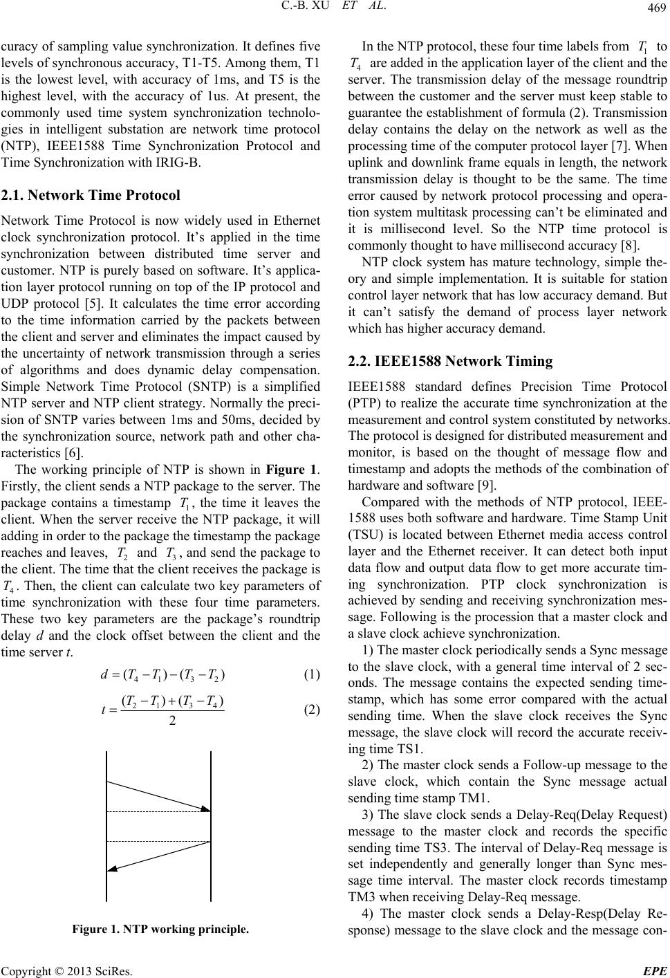 C.-B. XU ET AL. 469 curacy of sampling value synchronization. It defines five levels of synchronous accuracy, T1-T5. Among them, T1 is the lowest level, with accuracy of 1ms, and T5 is the highest level, with the accuracy of 1us. At present, the commonly used time system synchronization technolo- gies in intelligent substation are network time protocol (NTP), IEEE1588 Time Synchronization Protocol and Time Synchronization with IRIG-B. 2.1. Network Time Protocol Network Time Protocol is now widely used in Ethernet clock synchronization protocol. It’s applied in the time synchronization between distributed time server and customer. NTP is purely based on software. It’s applica- tion layer protocol running on top of the IP protocol and UDP protocol [5]. It calculates the time error according to the time information carried by the packets between the client and server and eliminates the impact caused by the uncertainty of network transmission through a series of algorithms and does dynamic delay compensation. Simple Network Time Protocol (SNTP) is a simplified NTP server and NTP client strategy. Normally the preci- sion of SNTP varies between 1ms and 50ms, decided by the synchronization source, network path and other cha- racteristics [6]. The working principle of NTP is shown in Figure 1. Firstly, the client sends a NTP package to the server. The package contains a timestamp 1, the time it leaves the client. When the server receive the NTP package, it will adding in order to the p a ckag e th e ti mestamp the p a ckag e reaches and leaves, 2 and 3 T, and send the package to the client. The time that the client receives the package is 4. Then, the client can calculate two key parameters of time synchronization with these four time parameters. These two key parameters are the package’s roundtrip delay d and the clock offset between the client and the time server t. T T T 41 32 ()(dTT TT) (1) 21 34 ()( 2 TT TT t ) (2) Figure 1. NTP working principle. In the NTP protocol, these four time labels from 1 to 4 are added in the application layer of the client and the server. The transmission delay of the message roundtrip between the customer and the server must keep stable to guarantee the establishment of formula (2). Transmission delay contains the delay on the network as well as the processing time of the computer protocol layer [7]. When uplink and downlink frame equals in length, the network transmission delay is thought to be the same. The time error caused by network protocol processing and opera- tion system multitask processing can’t be eliminated and it is millisecond level. So the NTP time protocol is commonly thought to have millisecond accuracy [8]. T T NTP clock system has mature technology, simple the- ory and simple implementation. It is suitable for station control layer network that has low accuracy demand. But it can’t satisfy the demand of process layer network which has higher acc ura cy dema nd. 2.2. IEEE1588 Network Timing IEEE1588 standard defines Precision Time Protocol (PTP) to realize the accurate time synchronization at the measurement and control syste m constituted by network s. The protocol is designed for distributed measurement and monitor, is based on the thought of message flow and timestamp and adopts the method s of the combination of hardware and software [9]. Compared with the methods of NTP protocol, IEEE- 1588 uses both software and hardware. Time Stamp Unit (TSU) is located between Ethernet media access control layer and the Ethernet receiver. It can detect both input data flow and output data flow to get more accurate tim- ing synchronization. PTP clock synchronization is achieved by sending and receiving synchronization mes- sage. Following is the procession that a master clock and a slave clock achieve synchronization. 1) The master clock periodically sends a Sync message to the slave clock, with a general time interval of 2 sec- onds. The message contains the expected sending time- stamp, which has some error compared with the actual sending time. When the slave clock receives the Sync message, the slave clock will record the accurate receiv- ing time TS1. 2) The master clock sends a Follow-up message to the slave clock, which contain the Sync message actual sending time stamp TM1. 3) The slave clock sends a Delay-Req(Delay Request) message to the master clock and records the specific sending time TS3. The interval of Delay-Req message is set independently and generally longer than Sync mes- sage time interval. The master clock records timestamp TM3 when receiving Delay-Req message. 4) The master clock sends a Delay-Resp(Delay Re- sponse) message to the slave clock and the message con- Copyright © 2013 SciRes. EPE 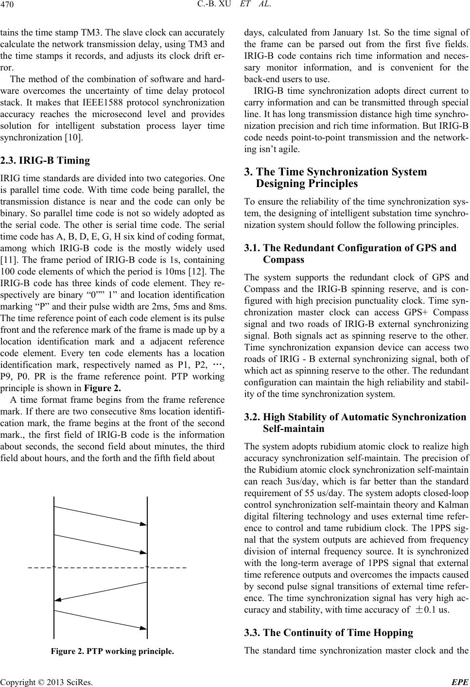 C.-B. XU ET AL. 470 tains the time stamp TM3. The slave clock can accurately calculate the network transmission delay, using TM3 and the time stamps it records, and adjusts its clock drift er- ror. The method of the combination of software and hard- ware overcomes the uncertainty of time delay protocol stack. It makes that IEEE1588 protocol synchronization accuracy reaches the microsecond level and provides solution for intelligent substation process layer time synchronizati o n [1 0] . 2.3. IRIG-B Timing IRIG time standards are divided into two categories. One is parallel time code. With time code being parallel, the transmission distance is near and the code can only be binary. So parallel time code is not so widely adopted as the serial code. The other is serial time code. The serial time code has A, B, D, E, G, H six kind of coding format, among which IRIG-B code is the mostly widely used [11]. The frame period of IRIG-B code is 1s, containing 100 code elements of which the period is 10ms [12]. The IRIG-B code has three kinds of code element. They re- spectively are binary “0”” 1” and location identification marking “P” and their pulse width are 2ms, 5ms and 8ms. The time reference point of each code element is its pulse front and the reference mark of the frame is made up by a location identification mark and a adjacent reference code element. Every ten code elements has a location identification mark, respectively named as P1, P2, …, P9, P0. PR is the frame reference point. PTP working principle is shown in Figure 2. A time format frame begins from the frame reference mark. If there are two consecutive 8ms location identifi- cation mark, the frame begins at the front of the second mark., the first field of IRIG-B code is the information about seconds, the second field about minutes, the third field about hours, and the forth and the fifth field about Figure 2. PTP working principle. days, calculated from January 1st. So the time signal of the frame can be parsed out from the first five fields. IRIG-B code contains rich time information and neces- sary monitor information, and is convenient for the back-end users to use. IRIG-B time synchronization adopts direct current to carry information and can be transmitted through special line. It has long transmission distance high time synchro- nization precision and rich time information. But IRIG-B code needs point-to-point transmission and the network- ing isn’t agile. 3. The Time Synchronization System Designing Principles To ensure the reliability of the time synchronization sys- tem, the designing of in telligent substation time synchro- nization system should follow the following principles. 3.1. The Redundant Configuration of GPS and Compass The system supports the redundant clock of GPS and Compass and the IRIG-B spinning reserve, and is con- figured with high precision punctuality clock. Time syn- chronization master clock can access GPS+ Compass signal and two roads of IRIG-B external synchronizing signal. Both signals act as spinning reserve to the other. Time synchronization expansion device can access two roads of IRIG - B external synchronizing signal, both of which act as spinning reserve to the other. The redundant configuration can maintain the h igh reliability and stabil- ity of the time synchronization system. 3.2. High Stability of Automatic Synchronization Self-maintain The system adopts rubidium atomic clock to realize high accuracy synchronization self-maintain. The precision of the Rubidium atomic clock synchronization self-maintain can reach 3us/day, which is far better than the standard requirement of 55 us/day. The system adopts closed-loop control synchronization self-maintain theory and Kalman digital filtering technology and uses external time refer- ence to control and tame rubidium clock. The 1PPS sig- nal that the system outputs are achieved from frequency division of internal frequency source. It is synchronized with the long-term average of 1PPS signal that external time reference outputs and overcomes the impacts caused by second pulse signal transitions of external time refer- ence. The time synchronization signal has very high ac- curacy and stability, with time accuracy of ±0.1 us. 3.3. The Continuity of Time Hopping The standard time synchronization master clock and the Copyright © 2013 SciRes. EPE 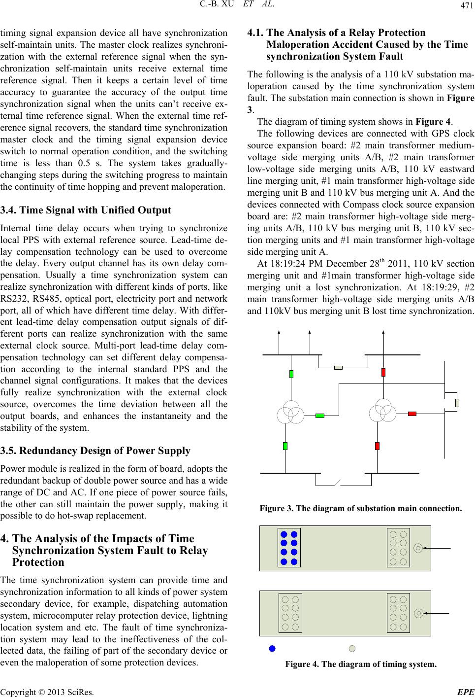 C.-B. XU ET AL. 471 timing signal expansion device all have synchronization self-maintain units. The master clock realizes synchroni- zation with the external reference signal when the syn- chronization self-maintain units receive external time reference signal. Then it keeps a certain level of time accuracy to guarantee the accuracy of the output time synchronization signal when the units can’t receive ex- ternal time reference signal. When the external time ref- erence signal recovers, the standard time synchronization master clock and the timing signal expansion device switch to normal operation condition, and the switching time is less than 0.5 s. The system takes gradually- changing steps during the switching pro gress to maintain the continuity of time hop ping and prevent maloperation. 3.4. Time Signal with Unified Output Internal time delay occurs when trying to synchronize local PPS with external reference source. Lead-time de- lay compensation technology can be used to overcome the delay. Every output channel has its own delay com- pensation. Usually a time synchronization system can realize synchronization with different kinds of ports, like RS232, RS485, optical port, electricity port and network port, all of which have different time delay. With differ- ent lead-time delay compensation output signals of dif- ferent ports can realize synchronization with the same external clock source. Multi-port lead-time delay com- pensation technology can set different delay compensa- tion according to the internal standard PPS and the channel signal configurations. It makes that the devices fully realize synchronization with the external clock source, overcomes the time deviation between all the output boards, and enhances the instantaneity and the stability of the system. 3.5. Redundancy Design of Power Supply Power module is realized in the form of board, adopts the redundant backup of double power source and has a wide range of DC and AC. If one piece of power source fails, the other can still maintain the power supply, making it possible to do hot-swap replacement. 4. The Analysis of the Impacts of Time Synchronization System Fault to Relay Protection The time synchronization system can provide time and synchronization information to all kinds of power system secondary device, for example, dispatching automation system, microcomputer relay protection device, lightning location system and etc. The fault of time synchroniza- tion system may lead to the ineffectiveness of the col- lected data, the failing of part of the secondary device or even the maloperation of some protection devices. 4.1. The Analysis of a Relay Protection Maloperation Accident Caused by the Time synchronization System Fault The following is the analysis of a 110 kV substation ma- loperation caused by the time synchronization system fault. The substation main connection is shown in Figure 3. The diagram of timing system shows in Fig u r e 4. The following devices are connected with GPS clock source expansion board: #2 main transformer medium- voltage side merging units A/B, #2 main transformer low-voltage side merging units A/B, 110 kV eastward line merging unit, #1 main transformer high-voltage side merging unit B and 110 kV bus merg ing unit A. And the devices connected with Compass clock source expansion board are: #2 main transformer high-voltage side merg- ing units A/B, 110 kV bus merging unit B, 110 kV sec- tion merging units and #1 main transformer high-voltage side merging unit A. At 18:19:24 PM December 28th 2011, 110 kV section merging unit and #1main transformer high-voltage side merging unit a lost synchronization. At 18:19:29, #2 main transformer high-voltage side merging units A/B and 110kV bus merging unit B lost time synchronization. Figure 3. The diagram of substation main connection. Figure 4. The diagram of timing system. Copyright © 2013 SciRes. EPE  C.-B. XU ET AL. 472 At 18:19:30, 110 kV section merging unit and #1main transformer high-voltage side merging unit A recovered time synchronization. At 18:19:34.824, #2 main trans- former high-voltage side merging units A/B and 110 kV bus merging unit B recovered time synchronization. At 18:19:34.891, #2 main transformer A differential protec- tion tripped three sides of switches 112, 312 and 012. After that, the inspection results showed that primary system devices hasn’t failed and this trip was preliminar- ily judged to be relay protection malfunction. In normal operation condition, merging units sample 4000 sampling point per second, counted from 0 to 3999. Every when the synchronization second pulse arrives, the merging units reset the sampling value and count the sampling points from 0. Main transformer differential protection trips according to the sample count. For ex- ample, if the sample count of h igh-voltage side sampling point is 0, the main transformer will compare it with the medium-voltage side and the low-voltage side sampling point sampling point whose sample count are 0. Table 1 shows the contrast of the synchronization of #2 main transformer merging unit A raw data of three sides during the accident. When the merging unit lost synchronization for three seconds, at 18:19:32.824345, the sample count hopped 705 frames from 3291 to 3996. At 18:19:34.824335, the merging unit recovered syn- chronization and the high-voltage side had a gap of 705 frames with the medium-voltage side and the low-voltage side. When recovered synchronization, the main trans- former judged that the sampling data was effective, opened the differential protection, and caused the mal- function of the differential operation. At 18:19:36.824652, the system lost synchronization again. Checking results showed that 110 kV bus merging unit, 110 kV section merging units, #1 main transformer merging unit A and #2 main transformer merging unit B all experienced the lost of synchronization, the hopping of count, the recovery of synchronization and the lost of synchronization once again. The hopping amplitudes are all 705 frames, but the hopping time and the recovery time were different. They lost synchronization again at the same time Field tests showed that #2 main transformer merging units had no synchronization self-maintain function. When the Compass system lost satellite signal, the sys- tem couldn’t switch to GPS time. Meanwhile all the ex- pansion boards on GPS clock source stopped sending timing signal, and thus the devices connected to the ex- pansion boards lost synchronization. According to the management of the merging units to sampling data dur- ing the accident, it is obvious that the merging units connected to the expansion boards on GPS clock all hopped the same extent o f 705 fram es . When the sampling lost synchronization, the main transformer locked the differential protection. When the sampling recovered synchronization, the main trans- former opened the differential protection and calculated the remainder of the sample count divided by 80 to make sure the synchronization of sampling points from three sides. On this condition, only time delay caused by net- work transmission was taken into consideration and the main transformer couldn’t deal correctly with the cases that the time difference longer than one cycle. The direct cause of the accident is the defect of the main transformer relay protection. When the sample count of three sides didn’t agree with each other, the dif- ferential protection was not normally locked and mal- functioned. The indirect cause is that the system couldn’t normally switch to GPS clock source and stopped send- ing timing signal when the system lost the Compass clock source signal. It directly caused the inconformity of the sample count of the three sides. Table 1. The contrast of the synchronization of #2 main transformer merging units A. Merging units A Time High -voltage count Medium -voltage Count Low -voltage count Note 18:19 :29.000838 3998 3997 3997 Losing synchroniza-tion, no hoppoing 18:19 :29.001323 0 3999 3999 18:19 :30.001343 0 3999 3999 18:19 :31.001343 0 3999 3999 18:19 :32.001343 0 3999 3999 18:19 :32.824345 3996 3291 3291 Hopping from 3291 to 3996 18:19 :32.82534 0 3294 3295 18:19 :33.825339 0 3294 3295 18:19 :34.824335 3995 3290 3291 Recovering synchro- niza-tion, no hopping 18:19 :34.82534 0 3294 3295 18:19 :34.89110 262 3557 3558 18:19 :36.824652 3998 3292 3293 Losing synchroniza-tion Copyright © 2013 SciRes. EPE  C.-B. XU ET AL. Copyright © 2013 SciRes. EPE 473 4.2. Some Improving Measures to Protection Devices and the Time Synchronization System On the basis of a detailed analysis of the cause of the accident, put forward the following suggestions and measures for protection devices and the time synchroni- zation system. 1) Some logical criterion should be added to the main transformer protection: when the sampling synchroniza- tion clock bit is “FALSE”, the main transformer should lock the differential protection; when the synchronization recovers, the sampling synchronization clock bit should switch to “TURE”. The main transformer protection should be able to judg e whether the sample counts of the three sides are consistent; if they aren‘t consistent, the main transformer protection should lock the differential protection until the sample counts recover accordance. 2) Eliminate the defects of the timing system, maintain the normal switch between different clocks, and make sure that there is no clock hopping during the switch. 3) The three merging units of the three sides of the same main transformer use the same clock expansion board. 4) In the case of double configuration of merging units, the two merging units of the same protection device can’t use the same clock expansion board. 5) The system should provide corresponding warning signals to the background. 6) Punctuality function should be added to merging units to satisfy relevant technical standards. 5. Conclusions The intelligent substation realizes the digitization of all the substation information, the network of communica- tion platform and the standardization of information sharing. All the devices and subsystems exchange data through fiber optic Ethernet, putting forward higher re- quirements to the substation time synchronization system. This paper introduces several time synchronization tech- nologies commonly used in practice, gives the design principles of time synchronization system, analyzes the impacts of time synchronization system error to protec- tion devices, and puts forward some improving measures, which is vital to the reliable operation of the intelligent substation. REFERENCES [1] Y.-C. Su and Q. Liu, “Time Synchronization and Its Ap- plication in Smart Substation,” Jiangxi Electric Power, Vol. 34, No. 4, 2010, pp. 6-8. [2] Z.-Y. Gao, C.-H. Li and R.-P. Liu, “Discussion on Ap- plication of Network-based Timing Technology in Power Plant and Substation Automation Systems,” Electric Power Automation Device, Vol. 26, No. 7, 2006, pp. 84-89. [3] X. Huang, Y. F. Wang, D. N. Zhang, Q. Li and B. Y. Bian, “IEC 61588 Time Synchronization System and Se- curity Evaluation for Smart Substations,” Automation of Electric Power Systems, Vol. 36, No. 13, 2012, pp. 76-80. [4] C. Fan, Y. M. Ni, J. Shen, Z. H. He, L. Xie and G. F. Huang, “Research on the Application of IEEE 1588 in the Merging Unit Based on IEC 61850-9-2,” Automation of Electric Power Systems, Vol. 35, No. 06, 2011. [5] Y. Wang, H. B. Zhao, Y. Xian, Z. Chen, L. Teng and L. F. Lu, “Applications and Development of High-Precision Time Synchronization System in the Power System,” Telecommunications for Electric Power System, Vol. 32, No. 219, 2011, pp. 16-19. [6] Y. Wang, H. B. Zhao, Y. Xian, Z. Chen, L. Teng and L. F. Lu, “Time Synchronizing System for Power System,” Automation of Electric Power Systems, Vol. 32, No. 7, 2008, pp. 82-86. [7] Y. Luo and L. Wang, “Analyze about Time Synchroniza- tion Technique in Auto-test Network System,” 2nd In- ternaitonal Conference on Future Computer and Com- munication, Vol. 1, 2010, pp. 831-834. [8] Z. L. Yin, W. S. Liu, Q. X. Yang and Y. L. Qin, “A New IEEE 1588 Based Technology for Realizing the Sampled Values Synchronization on the Substation Process Bus,” Automation of Electric Power Systems, Vol. 29, No. 13, 2005, pp. 60-63. [9] L. H. Wang, Y. Xu, Y. P. Lu, Y. B. Yuan and J. Sun, “Synchronized Sampling of Process Layer in Digital Sub- station,” Electric Power Automation Device, Vol. 30, No. 8, 2010, pp. 37-40. [10] L. Zhao and Y. F. Zhao, “Analysis and Experiment of Transparent Clock in Time Synchronization System of Smart Substation,” Automation of Electric Power Systems, Vol. 36, No. 6, 2012, pp. 106-111. [11] B. Zhao, G. F. Huang, Y. X. Wang and H. Zhang, “Time Synchronization with IRIG-B Code in Substation IED,” Electric Power Automation Device, Vol. 25, No. 9, 2005, pp. 86-88. [12] Z.-G., Bing, K. Shu and Y. F. Gu, “Application of IRIG-B Code in Time Synchronization System,” Modern Electronics Technique, Vol. 35, No. 7, 2012, pp. 16-18. |

