 Energy and Power Engineering, 2013, 5, 435-441 doi:10.4236/epe.2013.54B084 Published Online July 2013 (http://www.scirp.org/journal/epe) Copyright © 2013 SciRes. EPE Wide-Area Delay-Dependent Adaptive Supervisory Control of Multi-machine Power System Based on Improve Free W eighting Matrix Approach* Ziyong Zhang1, Zhijian Hu1, Yukai Liu1, Yang Gao2, He Wang1, Jianglei Suo1 1School of Electrical Engineering, Wuhan University, Wuhan, China. 2Jiangsu Suzhou Power Supply Company, STATE GRID Corporation of China, Suzhou, China Email: zzyhohai@163.com Received January, 2013 ABSTRACT The paper demonstrates the possibility to enhance the damping of inter-area oscillations using Wide Area Measurement (WAM) based adaptive supervisory controller (ASC) which considers the wide-area signal transmission delays. The paper uses an LMI-based iterative nonlinear optimization algorithm to establish a method of designing state-feedback controllers for power systems with a time-varying delay. This method is based on the delay-dependent stabilization conditions obtained by the improved free weighting matrix (IFWM) approach. In the stabilization conditions, the upper bound of feedback signal’s transmission delays is taken into consideration. Combining theories of state feedback con- trol and state observer, the ASC is designed and time-delay output feedback robust controller is realized for power sys- tem. The ASC uses the input information from Phase Measurement Units (PMUs) in the system and dispatches supple- mentary control signals to the available local controllers. The design of the ASC is explained in detail and its perfor- mance validated by time domain simulations on a New England test power system (NETPS). Keywords: Adaptive Supervisory Controller (ASC); Delay-de pendent Dampi ng Co ntrol; Power Oscillation; IFWM; LMI; Free Weighting Matrix Approa ch; Time-varying Delay; WAMS 1. Introduction WITH the deregulation of power systems, many tie lines between control areas are driven to operate near their maximum capacity, especially those serving heavy load centers. Stressed operating conditions can increase the inter-area oscillation between different control areas and can even break up the system. The incidents of system outage resulting from these oscillations are of growing concern. Over the past few decades, attention has been focused on designing controllers to dampen inter-area oscillations. The traditional method of damping inter-area oscillations is via the installation of power system stabilizers (PSS) which provide control action through the excitation con- trol of generators[1]. Local PSSs are usually tuned based on several typical operating conditions of corresponding generators. z An inappropriate coordination among the local controllers may cause serious problems [2]. It has been suggested that centralized controllers using wide-area signals rely on the PMUs technology[3]. PMUs are used to capture the power system’s dynamic data (e.g., voltages, currents, angles and frequency.) through synchronized measurements enabled by the GPS satellites. It has been shown that by using the remote signals the controller can enhance the damping of inter area oscillations and improve the overall dynamic per- formance of the power system[4]. A new PSS using two signals, the first to dampen the local mode in the area and the second, global signal, to dampen inter-area modes, is propose d in [5]. Application of techniques for designing robust power system damping controllers has been reported in the lite- rature [6-9]. The solution to the control design problem based on the method of Riccati equations usually pro- duces a controller that suffers from pole-zero cancella- tions between the system plant and the controller [10]. The application of the linear matrix inequality (LMI) approach as an alternative for damping controller design for PSS has been reported in [11,12]. A mixed -sensitivity based LMI approach has been applied to inter-area damping control design in [6,9]. In [9], FACTs are em- ployed to damp inter-area oscillations. However, the cost of FACTs devices is quite high so that it currently re- *This work is supported by Special Scientific and Research Funds for Doc- toral Speciality of Institution of Higher Learning(2011014111 0032) and Fundamental Research Funds for the Central Universities(2012207020205). 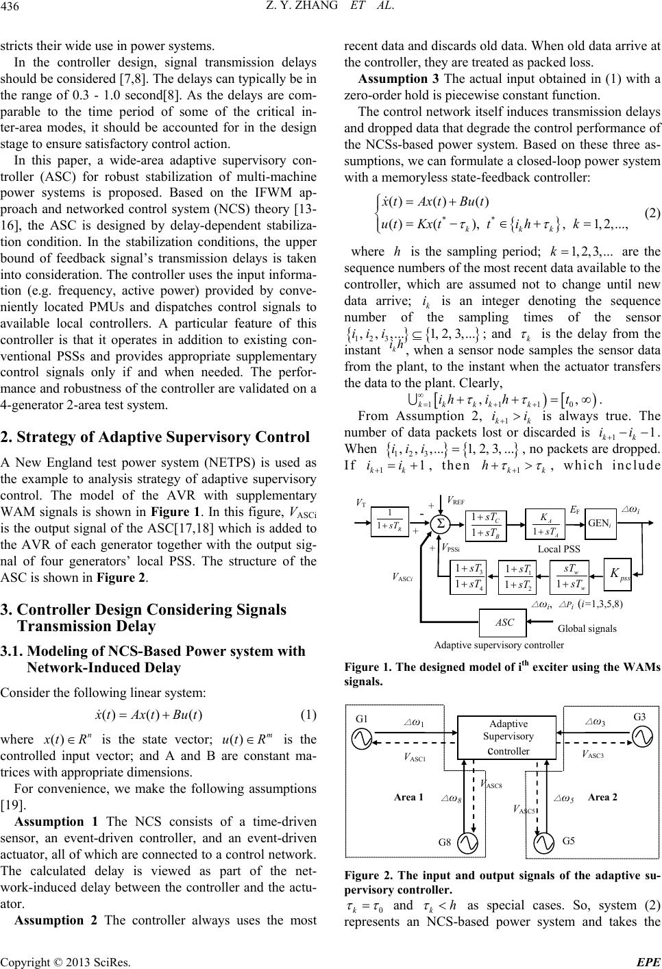 Z. Y. ZHANG ET AL. Copyright © 2013 SciRes. EPE stricts their wide use in power systems. In the controller design, signal transmission delays should be considered [7,8]. The delays can typically be in the range of 0.3 - 1.0 second[8]. As the delays are com- parable to the time period of some of the critical in- ter-area modes, it should be accounted for in the design stage to ensure satisfactory control action. In this paper, a wide-area adaptive supervisory con- troller (ASC) for robust stabilization of multi-machine power systems is proposed. Based on the IFWM ap- proach and networked control system (NCS) theory [13- 16], the ASC is designed by delay-dependent stabiliza- tion condition. In the stabilization conditions, the upper bound of feedback signal’s transmission delays is taken into consideration. The controller uses the input informa- tion (e.g. frequency, active power) provided by conve- niently located PMUs and dispatches control signals to available local controllers. A particular feature of this controller is that it operates in addition to existing con- ventional PSSs and provides appropriate supplementary control signals only if and when needed. The perfor- mance and robustness of the controller are validated on a 4-generator 2-area test system. 2. Strategy of Adaptive Supervisory Control A New England test power system (NETPS) is used as the example to analysis strategy of adaptive supervisory control. The model of the AVR with supplementary WAM signals is shown in Figure 1. In this figure, VASCi is the output signal of the ASC[17,18] which is added to the AVR of each generator together with the output sig- nal of four generators’ local PSS. The structure of the ASC is shown in Figure 2. 3. Controller Design Considering Signals Transmission Delay 3.1. Modeling of NCS-Based Power system with Network-Induced Delay Consider the following linear system: (1) where is the state vector; is the controlled input vector; and A and B are constant ma- trices with appropriate dimensions. For convenience, we make the following assumptions [19]. Assumption 1 The NCS consists of a time-driven sensor, an event-driven controller, and an event-driven actuator, all of which are connected to a control network. The calculated delay is viewed as part of the net- work-induced delay between the controller and the actu- ator. Assumption 2 The controller always uses the most recent data and discards old data. When old data arrive at the controller, they are treated as packed loss. Assumption 3 The actual input obtained in (1) with a zero-order hold is piecewise constant function. The control network itself induces transmission delays and dropped data th at de grade the control performance of the NCSs-based power system. Based on these three as- sumptions, we can formulate a closed-loop power system with a memoryless state-feedback controller: { } ** ()()() ( )(),,1,2,..., k kk x tAx tBu t u tKxtti hk ττ = + = −∈+= (2) where h is the sampling period; are the sequence numbers of the most recent data available to the controller, which are assumed not to change until new data arrive; k i is an integer denoting the sequence number of the sampling times of the sensor { } { } 123 ,,,...1, 2,3,...iii ⊆ ; and k τ is the delay from the instant , when a sensor node samples the sensor data from the plant, to the instant when the actuator transfers the data to the plant. Clearly, [ ) [ ) 11 10 k kkkk ihi ht ττ ∞ = ++ . From Assumption 2, 1 +> is always true. The number of data packets lost or discarded is 11 + . When { } { } 123 ,,,...1, 2, 3,...iii = , no packets are dropped. If 11 +=+ , then 1 h + , which include Adap tive supervisory controller Figure 1. The de signed model of ith exciter using the WAMs signals. Adaptive Supervi sory c ontroller Figure 2. The input and output signals of the adaptive su- pervisory controller. 0k = and as special cases. So, system (2) represents an NCS-based power system and takes the 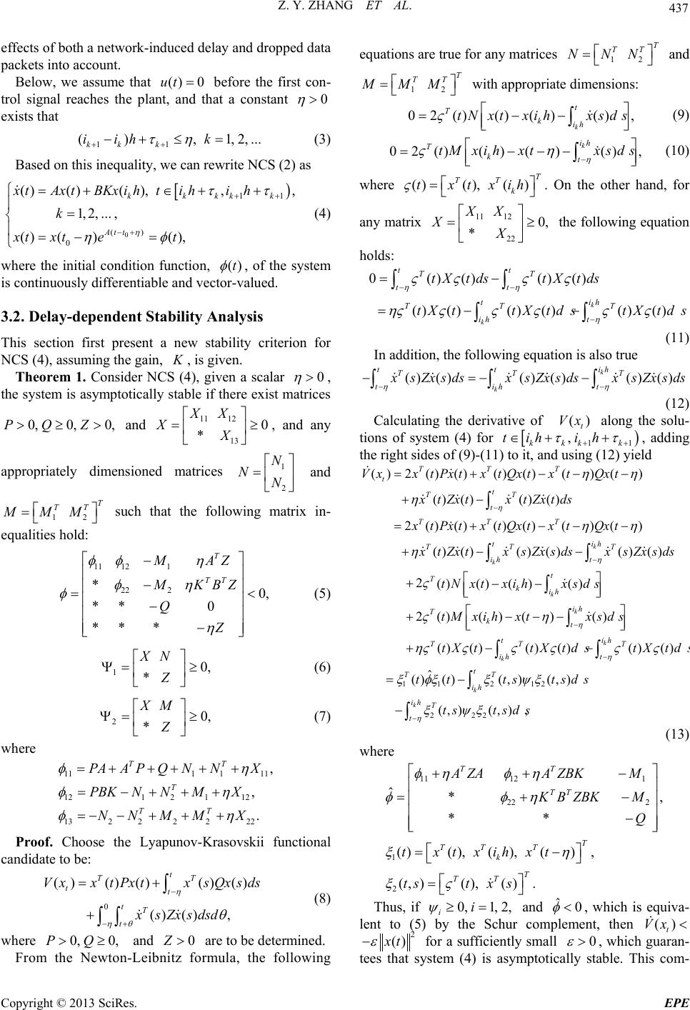 Z. Y. ZHANG ET AL. Copyright © 2013 SciRes. EPE effects of both a network-induced delay and dropped data packets into account. Below, we assume that () 0ut = before the first con- trol signal reaches the plant, and that a constant exists that 11 (),1,2,... kk k i ihk τη ++ −+≤ = (3 ) Based on this inequality, we can rewrite NCS (2) as ) 0 () 0 ()()( ),,, 1,2,..., () ()(), kkkkk At t xtAxt BKxiht ihih k xt xtet η ηφ −+ = +∈++ = =−= (4) where the initial condition function, φ , of the system is continuously differentiable and vector-valued. 3.2. Delay-dependent Stability Analysis This section first present a new stability criterion for NCS (4), as s u ming the gain, , is given. Theorem 1. Consider NCS (4), given a scalar , the system is asymptotically stable if there exist matrices and 11 12 13 0 * XX XX = ≥ , and any appropriately dimensioned matrices 1 2 N NN = and T M MM = such that the following matrix in- equalities hold: 11 121 22 2 *0, **0 ** * T TT M AZ M KBZ Q Z φφ η φη φ η − − = < − − (5) (6) (7) where 111 111 121 2112 132 22222 , , . TT T TT PAAPQNNX PBK NNMX NNMM X φη φη φη =+++ ++ =−++ + =−− +++ Proof. Choose the Lyapunov-Krasovskii functional candidate to be: 0 ( )()()()() ()(), t tt tT t VxxtPx txs Qx sds xs Zx s dsd η ηθ θ − −+ = + + ∫ ∫∫ (8 ) where and are to be determined. From the Newton-Leibnitz formula, the following equations are true for any matrices T N NN = and with appropriate dimensions: 0 2 ()()()(), k t Tkih tN xtxihxsds ς = −− ∫ (9) 0 2 ()()()(), k ih Tkt tMxihxtxsds η ςη − =− −− ∫ (10) where ()(),()T TT k txtxih ς = . On the other hand, for any matrix 1112 22 0, * XX XX = ≥ the following equation holds: 0() ()() () () ()() ()() () k k tt TT tt t ih ih t tXt dstXt ds tX ttX tdstX tds ηη η ςς ςς −− − = − ∫∫ (11) In addition, the following equation is also true () ()() ()()() k k tt ih tih t xs Zx s dsxs Zx s dsxs Zx sds ∫ ∫∫ (12) Calculating the derivative of along the solu- tions of system (4) for , adding the right sides of (9)-(11) to it, and using (12) yield ()2()()()()()() ()()()() 2()()()()()() ()()()()()() 2 k k TTT t t TT t TTT t ih TT T ih t T VxxtPxtxtQxtx tQxt xtZx txtZxtds x tPxtx tQxtx tQxt xtZx txs Zx s dsxs Zx s ds η η ηη η ηη η ς − − =+−− − +− =+−− − +− − + ∫ ∫∫ 1 1212 2 22 ()()()() 2 ()()()() () ()() ()()() ˆ ()()(, )(, ) (,)(,) k k k k k k t kih ih Tkt t ih TT T ih t t TT ih ih T t tN xtxihxsds tM xihxtxsds tX ttXtdstXtds t ttstsds ts tsds η η η ςη ηςς ςςςς ξφξξψξ ξ ψξ − − − −− +− −− +− − = − − ∫ ∫ ∫∫ ∫ , ∫ (13) where 11 121 22 2 1 2 ˆ*, ** ( )(),(),(), ( ,)(),(). TT TT T TTT k T TT A ZAA ZBKM KBZBKM Q txtxih xt tstx s φη φη φ φη ξη ξς ++ − = +− − = − = Thus, if 0,1, 2, ii ψ ≥= and 0 φ <, which is equiva- lent to (5) by the Schur complement, then for a sufficiently small , which guaran- tees that system (4) is asymptotically stable. This com-  Z. Y. ZHANG ET AL. Copyright © 2013 SciRes. EPE pletes the proof. When and (where is a suffi- ciently small scalar), the following corollary readily fol- lows from Theorem 1. Corollary 1 Consider NCS (4), given a scalar , the system is asymptotically stable if there exist matrices and , and any appro- priately dimensioned matrix such that ma- trix inequality (6) and the following one hold: 11 12 22 * 0, ** T TT AZ KBZ Z η η η ΞΞ Ξ= Ξ< − (14) where 111 111 121 212 222 222 , , . TT T T PAAPNNX PBK NNX NN X η η η Ξ=++++ Ξ=−++ Ξ=− −+ 3.3. Design of State F eedback Controller Theorem 1 is extended to the design of a stabilization controller with gain for syste m (4). Theorem 2. Consider NCS (4), for a given scalar , if there exist matrices and 11 12 22 0, * YY YY = ≥ and any appropriately dimensioned matrices 12 12 , TT TT TT SSSTTT = = , and such that the following matrix inequalities hold: 11 121 22 2 *0, ** 0 *** T TT T LA T VB W R η η η ΞΞ− Ξ− Ξ= < − − (15) 110, * YS LR L − Π= ≥ (1 6 ) (1 7 where 111 111 121 2 112 22222 222 , , . TT T TT AL LAWSSY BV SSTY SS TTY η η η Ξ=+++ ++ Ξ=−+++ Ξ=− −+++ then the system is asymptotically stable, and 1 K VL− = is a stabilizing controller gain. Proof. Pre-and post-multiply in (5) by diag , and pre- and post-multiply ,1, 2, ii ψ = in (6) and (7) by di ag . Then, make the following changes to the variables: { }{ } 11 11 11 ,,, ,,1, 2, , ,,. i iii L PR ZVKL SLN LTLMLi WLQLYdiag PPXdiag PP −− −− −− = = = = == = =⋅⋅ These manipulations yield matrix inequalities (15)- (17). This completes the proof. Note that the conditions in Theorem 2 are no longer LMI conditions due to the term in (16) and (17). Thus, that cannot use a convex optimization algorithm to obtain an appropriate gain matrix, , for the state- feedback controller. This problem can be solved by using the idea for solving a cone complementarity problem [20]. Define a new variable, U, for which ; and let PLHU ==and . Now, we convert the nonconvex problem into the following LMI-based nonli- near minimization problem: Minimize Subject to (15) and 0, 0,0, ** * 0,0,0. ** * YS YTHP UU Z LI UIRI P HZ ≥≥ ≥ ≥ ≥≥ (18) We use the ICCL algorithm to obtain and optimal K for power systems because of its advantages. Algorithm. Step1: Choose a sufficiently small initial , such that there exists a feasible solution to (15) and (18). Set a specified number of iterations N. Step2:Find a feasible set of values satisfying (15) and (18), 0000 00 (,, ,,,,,,,,)PLWSTYZRU HV .Set 0k= Step3: Solve the following LMI problem for the va- riables ,, ,,,,,,, ,,PLWSTYZRUHV and : Minimize { } kkk kkk TrLPLPUHUHRZRZ++ +++ Subject to (15) and (1 8). Set kkkk k P PLLUUHHRR ===== and 1k +=. Step4: For the obtained in step 3, if LMIs (15) and (18) are feasible for the variables and , then set max =, increase , and return to Step 2. If LMIs (5)-(7) are infeasible and without a spe- cified number of iterations, then exit. Otherwise, set 1kk= + and go to Step 3. Figure 3 shows the flowchart of nonlinear iterative optimization algorithm for the state feedback controller design. This condition and nonlinear iterative optimiza- tion algorithm, which has an improved stop condition, are used to design a state-feedback networked controller. But the operating state variables of wide-area power sys-  Z. Y. ZHANG ET AL. Copyright © 2013 SciRes. EPE tem cannot be completely observed, it is necessary to use measurable states. Here, combining theories of state feedback control and state observer, the ASC is designed and time-delay ou tput feedback robust control is realized for power system[21]. 4. Study System The New England test power system (NETPS) which consists of ten synchronous units in the sys tem connected by weak tie-lines is shown in Figure 4[22]. This system is considered to be one of the benchmark models for performing studies on inter-area oscillations because of its realistic structure and availability of system parame- ters. To validate the designed robust controller, the follow- ing disturbances were considered: Case 1: A 2-phase fault at one of the lines between buses 6-11 followed by successful auto-reclosing of the circuit breaker after 4 cycles; Case 2: A 3-phase fault at one of the lines between buses 6-11 followed by successful auto-reclosing of the circuit breaker after 4 cycles; { } kkk kkk TrLPL PUHUHRZRZ++ +++ 0000 00 (,, ,,,,,,,,)PLWSTYZRU HV Minimise Subject to (15) and (18) Set Find a feasible set of values stasfiying (15) and (18) : and then set k=0 Input matrix A and B Set iteration nunber N and step Choose a small initial values Satisfy (15) and (18)?k<=N? Stop ? 111 1 11 ,, ,, , kkk k kk SetPPLLUUHH RRandZZ ++ ++ ++ = === = = Output the required state feedback controller Figure 3. Flowchart of nonlinear iterative optimization al- gorithm. 5. Simulation Results To validate the performance and robustness of the pro- posed control scheme involving ASC, simulations were carried out corresponding to the probable fault scenarios in the test system. If no time delay was considered, the simulation results were given in [17,18]. In each of the two cases, the total time delay for the feedback signals to arri ve at th e controller, then for the controller to send th e signals to AVRs is 0.5 seconds. 5.1. Case 1 The rotor speed difference responses of multi-machine power system following a 2-phase fault are shown in Figures 5 and 6. 5.2. Case 2 The rotor speed difference responses of multi-machine power system following a 3-phase fault are shown in Figures 7 and 8. 1 10 9 8 7 6 5 4 32 30 37 25 26 28 29 27 38 21 16 17 183 2 1 39 15 14 2436 23 22 35 4 5 96 11 12 13 19 20 7 8 10 31 3234 33 Ld15 L26 L25 Ld16 Figure 4. The New England test power system. 0510 15 -6 -4 -2 0 2 4 6x 10⁻⁴ time,seco nd rotor speed (G3-G4) (p.u.) without ASC with ASC an d 0.5s signal tran smission delay Figure 5. Rotor speed difference response of G3 and G4 following a 2-phase fault.  Z. Y. ZHANG ET AL. Copyright © 2013 SciRes. EPE 05 10 15 -4 -3 -2 -1 0 1 2 3 4x 10 -4 tim e,second rotor speed (G2-G3) (p.u.) withou t ASC with AS C and 0.5s signal tran smission delay Figure 6. Rotor speed difference response of G2 and G3 following a 2-phase fault. 05 10 15 -1.5 -1 -0.5 0 0.5 1 1.5x 10⁻³ tim e,second rotor speed (G3-G4) (p.u.) withou t ASC with ASC and 0. 5s signal transmission delay Figure 7. Rotor speed difference response of G3 and G4 following a 3-phase fault. 05 10 15 -1.5 -1 -0.5 0 0.5 1 1.5x 10⁻³ time,second rotor speed (G2-G3) (p.u.) without ASC with ASC and 0. 5s signal transmission delay Figure 8. Rotor speed difference response of G2 and G3 following a 3-phase fault. 6. Conclusions A wide-area adaptive supervisory controller (ASC) for the robust stabilization of multi-machine power systems accounting for the time delays of feedback signals from remote locations is proposed. This paper first uses the IFWM approach to establish an improved stability condi- tion for NCSs-based power system that does not ignore any terms in the derivative of the Lyapunov-Krasovskii functional, but rather considers the relation ships among a network -induced delay, its upper bound, and the differ- ence between them. This condition and an ICCL algo- rithm, which has an improved stop condition, are used to design a state-feedback networked controller. Combining theories of state feedback control and state observer, the ASC is designed and time-delay output feedback robust control is realized for power system. With the control of the ASC, the system oscillations reduce considerably. Additionally, the ASC ensures system stability even in the case of cascading faults. REFERENCES [1] P. Kundur, Power system stability and control, New York: McGraw-Hill, 1994. [2] G. J. Rogers, “The Application of Power System Stabiliz- ers to a Multi-Generator Plant,” IEEE Transacti Power Systems, Vol. 15, No. 1,2000. doi:10.1109/59.852143 [3] B. Bhargava, “Synchronized Phasor Measurement System Project at Southern California Edison Co.,” in Proc. IEEE power Engineering Society Summer Meeting, 1999, pp. 16-22. [4] H. Ni, G. T. Heydt and L. Mili, “Power System Stability Agents Using Robust Wide Area Control,” IEEE Tran- sacti Power Systems, Vol. 17, No. 4, 2002, pp. 1123-1131.doi:10.1109/TPWRS.2002.805016 [5] M. E. Aboul-Ela, A. A. Sallam, J. D. McCalley and A. A. Fouad, “Damping Controller Design for Power System Oscillation,”IEEE Transacti Power Systems, Vol. 11, No. 2, , 1996, pp. 76 7-773. doi:10.1109/59.496152 [6] M. Klein, L. Le, G. Rogers, S. Farrokpay and N. Balu, “H∞ Damping Controller Design in Large Power Sys- tem,” IEEE Transacti Power Systems, Vol. 10, No. 1, 1995, pp. 158-166. doi:10.1109/59.373938 [7] H. Wu, S. Tsakalis and G. T. Heydt, “Evaluation of Time Delay Effects to Wide-area Power System Stabilizer De- sign,” IEEE Transacti Power Systems, Vol. 19, No. 4, 2004, pp. 1935-1941. doi:10.1109/TPWRS.2004.836272 [8] B. Chaudhuri, R. Majumder and B. Pal, “Wide Area Mea- surement Based Stabilizing Control of Power System Considering Signal Transmission Del ay,” IEEE Transacti Power Systems, Vol. 19, No. 4, 2004, pp. 1971-1979. doi:10.1109/TPWRS.2004.835669 [9] B. Chaudhuri, B. Pal, A. C. Zolotas, I. M. Jaimoukha and T. C. Green, “Mixed-sensitivity approach to H∞ control of power system oscillations employing multiple facts devices,” IEEE Transacti P ower Systems, Vol. 18, No. 3, 2003, pp. 1149-1156. doi:10.1109/TPWRS.2003.811311 [10] S. Skogestad and I. Postlethwaite, Multivariable feedback control, John Wiley and Sons, UK, 2001. [11] P. Gahinet and P. Apkarian, “A Linear Matrix Inequality Approach to H∞ Control,” International Journal of Ro- bust and Non-linear Control, Vol. 4, No. 4, 1994, pp. 421-448. doi:10.1002/rnc.4590040403 [12] C. Scherer, P. Gahinet and M. Chilali, “Multi-Objective  Z. Y. ZHANG ET AL. Copyright © 2013 SciRes. EPE Output Feedback Control Via LMI Optimization,” IEEE Transacti Automatic Control, Vol. 42, No. 7, 1997, pp. 896-911. doi:10.1109/9.599969 [13] Jianhua Z, Guolian H, Yunze W, et al., “Networked Con- trol For Robotic Manipulators Via T-S Fuzzy Control And Descriptor Representation,” 2006. [14] Zhigang X, Chaoyang D, Lijie X, et al., Networked Con- trol of Guided Weapon Using Time -delay Switched Sys- tem with Compensatory Model[C]. 2009. [15] G. C. Goodwin, H. Haimovich, D. E. Quevedo, et al., “A Moving Horizon Approach to Networked Control System Design, Automatic Control, IEEE Transactions on, Vol. 49, No. 9, 2004, pp. 1427-1445. doi:10.1109/TAC.2004.834132 [16] G. P. Liu, Y. Q. Xia, D. Rees and W. S. Hu, “Design and Stability Criteria of Networked Predictive Control Sys- tems With Random Network Delay in the Feedback Channel,” Systems, Man, and Cybernetics, Part C: Ap- plications and Reviews, IEEE Transactions on, Vol. 37, No. 2, 2007, pp. 173-184. doi:10.1109/TSMCC.2006.886987 [17] Z. Hu and J. V. Milanović, “Damping of Inter-area Oscil- lations by WAM Based Supplementary Controller,” in Proc. IEEE PES GM 2007, 24-28 June 2007, Tampa, Florida, USA. [18] Z. Hu and J. V. Milanović, “The Effectiveness of WAM Based Adaptive Supervisory Controller for Global Stabi- lization of Power Systems,” in Proc. IEEE Power Tech 2007, 1-5, July 2007, Lausanne, Switzerl and. [19] F.-L. Lian, J. K. Yook, D. M. Tilbury, et al., “Network Architecture and Communication Modules for Guaran- teeing Acceptable Control and Communication Perfor- mance for Networked Multi-agent Sy st ems,” Industrial Informatics, IEEE Transactions on, Vol. 2, No. 1, 2006, pp. 12-24. doi:10.1109/TII.2005.857611 [20] L. El Ghaoui, F. Oustry and M. Aitrami, “A Cone Com- plementarity Linearization Algorithm for Static Out- put-Feedback and Related Problems,” Automatic Control, IEEE Transactions on. Vol. 42, No. 8, 1997, pp. 1171-1176. doi:10.1109/9.618250 [21] F. Liu, R. Yokoy a ma, Y. Zhou, et al., SVC Robust Addi- tional Damping Controller Design for Power System with Considering Time-delay of Wide-area Signals. 2010. [22] E. Vittal, M. O'Malley and A. Keane, “Rotor Angle Sta- bility With High Penetrations of Wind Generation,” Power Systems, IEEE Transactions on, Vol. 27, No. 1, 2012, pp. 353-362. doi:10.1109/TPWRS.2011.2161097
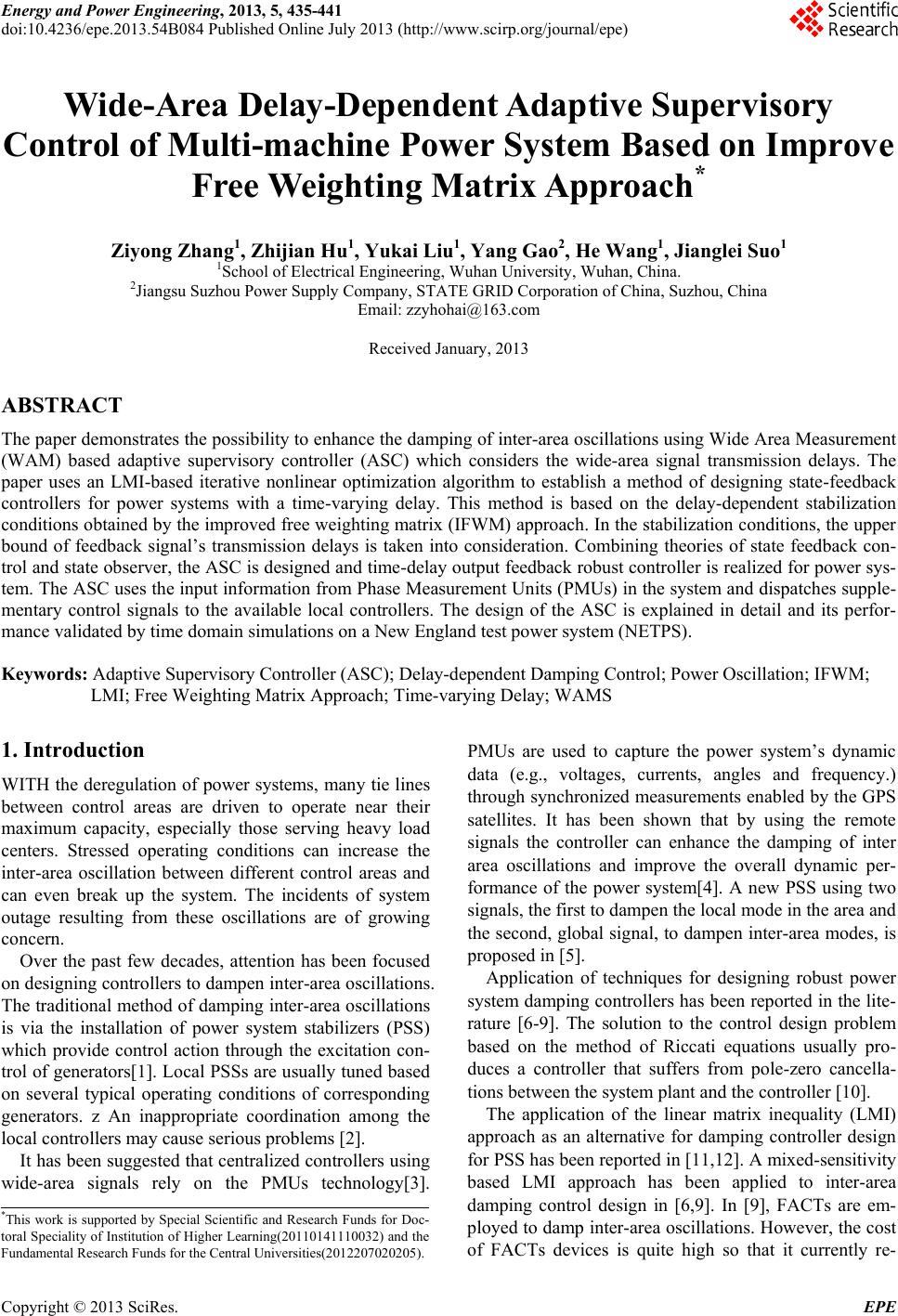
|