 Journal of Surface Engineered Materials and Advanced Technology, 2013, 3, 20-28 http://dx.doi.org/10.4236/jsemat.2013.34A1003 Published Online October 2013 (http://www.scirp.org/journal/jsemat) Copyright © 2013 SciRes. JSEMAT Characterization of Pectin Nanocoatings at Polystyrene and Titanium Surfaces Katarzyna Gurzawska1,2*, Kai Dirscherl3, Yu Yihua4, Inge Byg5, Bodil Jørgensen5, Rikke Svava5, Martin W. Nielsen6, Niklas R. Jørgensen1, Klaus Gotfredsen2 1Research Center for Ageing and Osteoporosis, Departments of Medicine and Diagnostics, Copenhagen University Hospital Glostrup, Glostrup, Denmark; 2Institute of Odontology, Faculty of Health and Medical Sciences, University of Copenhagen, Copenhagen, Denmark; 3Dansk Fundamental Metrologi A/S, Lyngby, Denmark; 4Microtechnology and Surface Analysis, Danish Technological Institute, Taastrup, Denmark; 5Department of Plant and Environment Sciences, Faculty of Science, University of Copenhagen, Frederiksberg, Denmark; 6Department of Systems Biology, Technical University of Denmark, Lyngby, Denmark. Email: *kagu@sund.ku.dk Received June 20th, 2013; revised July 19th, 2013; accepted August 6th, 2013 Copyright © 2013 Katarzyna Gurzawska et al. This is an open access article distributed under the Creative Commons Attribution License, which permits unrestricted use, distribution, and reproduction in any medium, provided the original work is properly cited. ABSTRACT The titanium implant surface plays a crucial role for implant incorporation into bone. A new strategy to improve im- plant integration in a bone is to develop surface nanocoatings with plant-derived polysaccharides able to increase adhe- sion of bone cells to the implant surface. The aim of the present study was to physically characterize and compare poly- styrene and titanium surfaces nanocoated with different Rhamnogalacturonan-Is (RG-I) and to visualize RG-I nano- coatings. RG-Is from potato and apple were coated on aminated surfaces of polystyrene, titianium discs and titanium implants. To characterize, compare and visualize the surface nanocoatings measurements of contact angle measure- ments and surface roughness with atomic force microscopy, scanning electron microscopy, and confocal microscopy was performed. We found that, both unmodified and enzymatic modified RG-Is influenced surface wettability, without any major effect on surface roughness (Sa, Sdr). Furthermore, we demonstrated that it is possible to visualize the pectin RG-Is molecules and even the nanocoatings on titanium surfaces, which have not been presented before. The compari- son between polystyrene and titanium surface showed that the used material affected the physical properties of non-coated and coated surfaces. RG-Is should be considered as a candidate for new materials as organic nanocoatings for biomaterials in order to improve bone healing. Keywords: Surface Properties; Titanium; Polystyrene; Rhamnogalacturonan-I; Osseointegration 1. Introduction The implant surface plays a crucial role for implant in- corporation into the bone and implant surface modifica- tions which are continuously developed in attempts to enhance and accelerate bone formation at the implant surface [1-5]. The development has been approached by chemically and physically modifications of the surface [1,3-8]. The first concept focuses on incorporating inor- ganic and/or organic molecules at the surface whereas the second focuses on changing surface properties in- cluding the surface topography [3,9]. The chemical and physical surface modification can be performed at dif- ferent levels [1,3,6]. From a biological point of view, the osseointegration process takes place at the cellular level, and therefore especially micro and nanoscale investiga- tions have great importance for developing new surfaces [4,6]. It has been demonstrated that nanoscale modifica- tion of titanium implants affects surface properties, such as hydrophilicity, biochemical bonding capacity and roughness, which influence cell behaviour on the surface such as adhesion, proliferation and differentiation of cells as well as the mineralization of the extracellular matrix at the implant surfaces [2,4-6,9-12]. The inorganic and organic nanocoatings are continu- ously developed and tested in vitro and in vivo. For in vitro examination, Tissue Culture Polystyrene Surfaces (TCPS) or titanium discs (Grade 2 or 4) are most fre- quently used [9], whereas for in vivo experiments tita- nium implant surfaces of Grade 4 titanium are the most frequently used [1,12]. To obtain the best conformity be- *Corresponding author. 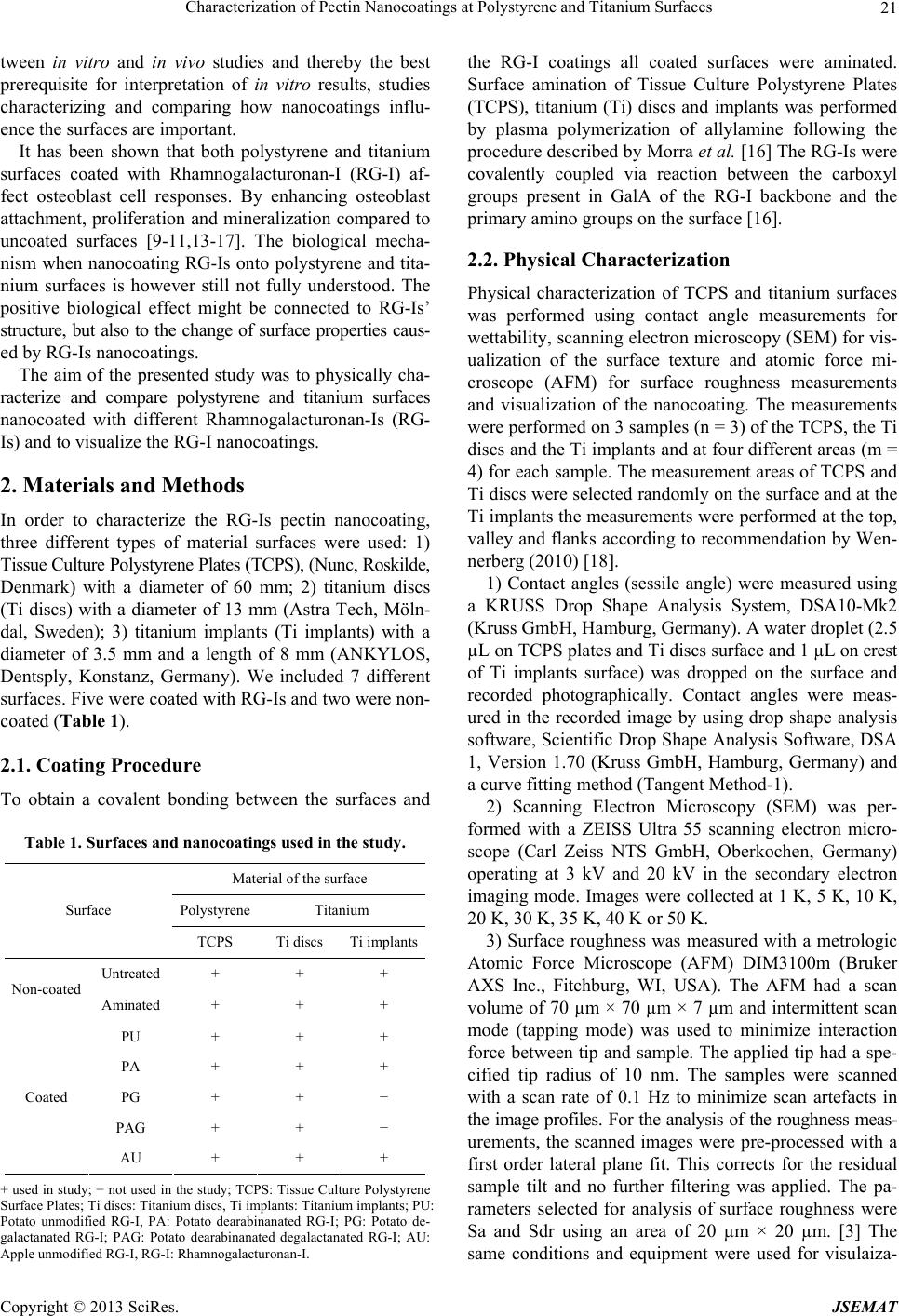 Characterization of Pectin Nanocoatings at Polystyrene and Titanium Surfaces Copyright © 2013 SciRes. JSEMAT 21 tween in vitro and in vivo studies and thereby the best prerequisite for interpretation of in vitro results, studies characterizing and comparing how nanocoatings influ- ence the surfaces are important. It has been shown that both polystyrene and titanium surfaces coated with Rhamnogalacturonan-I (RG-I) af- fect osteoblast cell responses. By enhancing osteoblast attachment, proliferation and mineralization compared to uncoated surfaces [9-11,13-17]. The biological mecha- nism when nanocoating RG-Is onto polystyrene and tita- nium surfaces is however still not fully understood. The positive biological effect might be connected to RG-Is’ structure, but also to the change of surface properties caus- ed by RG-Is nanocoatings. The aim of the presented study was to physically cha- racterize and compare polystyrene and titanium surfaces nanocoated with different Rhamnogalacturonan-Is (RG- Is) and to visualize the RG-I nanocoatings. 2. Materials and Methods In order to characterize the RG-Is pectin nanocoating, three different types of material surfaces were used: 1) Tissue Culture Polystyrene Plates (TCPS), (Nunc, Roskilde, Denmark) with a diameter of 60 mm; 2) titanium discs (Ti discs) with a diameter of 13 mm (Astra Tech, Möln- dal, Sweden); 3) titanium implants (Ti implants) with a diameter of 3.5 mm and a length of 8 mm (ANKYLOS, Dentsply, Konstanz, Germany). We included 7 different surfaces. Five were coated with RG-Is and two were non- coated (Table 1). 2.1. Coating Procedure To obtain a covalent bonding between the surfaces and Table 1. Surfaces and nanocoatings used in the study. Material of the surface Polystyrene Titanium Surface TCPS Ti discs Ti implants Untreated + + + Non-coated Aminated + + + PU + + + PA + + + PG + + − PAG + + − Coated AU + + + + used in study; − not used in the study; TCPS: Tissue Culture Polystyrene Surface Plates; Ti discs: Titanium discs, Ti implants: Titanium implants; PU: Potato unmodified RG-I, PA: Potato dearabinanated RG-I; PG: Potato de- galactanated RG-I; PAG: Potato dearabinanated degalactanated RG-I; AU: Apple unmodified RG-I, RG-I: Rhamnogalacturonan-I. the RG-I coatings all coated surfaces were aminated. Surface amination of Tissue Culture Polystyrene Plates (TCPS), titanium (Ti) discs and implants was performed by plasma polymerization of allylamine following the procedure described by Morra et al. [16] The RG-Is were covalently coupled via reaction between the carboxyl groups present in GalA of the RG-I backbone and the primary amino groups on the surface [16]. 2.2. Physical Characterization Physical characterization of TCPS and titanium surfaces was performed using contact angle measurements for wettability, scanning electron microscopy (SEM) for vis- ualization of the surface texture and atomic force mi- croscope (AFM) for surface roughness measurements and visualization of the nanocoating. The measurements were performed on 3 samples (n = 3) of the TCPS, the Ti discs and the Ti implants and at four different areas (m = 4) for each sample. The measurement areas of TCPS and Ti discs were selected randomly on the surface and at the Ti implants the measurements were performed at the top, valley and flanks according to recommendation by Wen- nerberg (2010) [18]. 1) Contact angles (sessile angle) were measured using a KRUSS Drop Shape Analysis System, DSA10-Mk2 (Kruss GmbH, Hamburg, Germany). A water droplet (2.5 µL on TCPS plates and Ti discs surface and 1 µL on crest of Ti implants surface) was dropped on the surface and recorded photographically. Contact angles were meas- ured in the recorded image by using drop shape analysis software, Scientific Drop Shape Analysis Software, DSA 1, Version 1.70 (Kruss GmbH, Hamburg, Germany) and a curve fitting method (Tangent Method-1). 2) Scanning Electron Microscopy (SEM) was per- formed with a ZEISS Ultra 55 scanning electron micro- scope (Carl Zeiss NTS GmbH, Oberkochen, Germany) operating at 3 kV and 20 kV in the secondary electron imaging mode. Images were collected at 1 K, 5 K, 10 K, 20 K, 30 K, 35 K, 40 K or 50 K. 3) Surface roughness was measured with a metrologic Atomic Force Microscope (AFM) DIM3100m (Bruker AXS Inc., Fitchburg, WI, USA). The AFM had a scan volume of 70 µm × 70 µm × 7 µm and intermittent scan mode (tapping mode) was used to minimize interaction force between tip and sample. The applied tip had a spe- cified tip radius of 10 nm. The samples were scanned with a scan rate of 0.1 Hz to minimize scan artefacts in the image profiles. For the analysis of the roughness meas- urements, the scanned images were pre-processed with a first order lateral plane fit. This corrects for the residual sample tilt and no further filtering was applied. The pa- rameters selected for analysis of surface roughness were Sa and Sdr using an area of 20 µm × 20 µm. [3] The same conditions and equipment were used for visulaiza-  Characterization of Pectin Nanocoatings at Polystyrene and Titanium Surfaces Copyright © 2013 SciRes. JSEMAT 22 tion of RG-I nanocoatings on titanium implant surfaces, but the measurements were performed with 1 × 1 µm scan area. 2.3. Visualization of RG-Is Nanocoatings 1) For visualization of RG-Is structures Atomic Force Microscopy (AFM) imaging was performed using a mul- timode AFM (Bruker AXS Inc., Fitchburg, WI, USA) with a Nano V controller. RG-Is from potato unmodified (PU), potato dearabinanated (PA), potato degalactanated (PG), potato dearabinanated degalactanated (PAG) and apple unmodified (AU) were dispersed into mili-Q water to a concentration of 1 µg·mL−1. Aliquots (10 mL−1) of the diluted RG-Is samples were deposited onto a freshly- cleaved molecularly smooth surface [19-21] (Mica sur- faces, Sa ~ 0 nm, Tedpella, Redding, CA, USA) and al- lowed to dry under ambient conditions before imaging by AFM in air [22]. The samples were scanned in inter- mittent “tapping” mode with commercial tips “SSS-NCH” from NanoSensors with a tip radius of 2 nm. Scannings was performed in ambient conditions. The scan rate was set to 0.5 Hz to limit the scan speed to 1 μm/s for a typi- cal sized image of 1 µm × 1 µm. Using the image proc- essing software SPIP (Image Metrology, Hørsholm, Den- mark), the data was line-wise tilt-corrected with a first order fit restricted to the data points of the Mica surface only. This allows accurate height measurements relative to the flat Mica reference surface with measurement un- certainties below 1 nm. 2) Immunofluorescence labeling and confocal micros- copy was performed on four implants, one non-coated aminated Ti implant and three coated Ti implants with (PU, PA, AU). The implants were placed in polystyrene 24-well plate (Nunc, Roskilde, Denmark) in separated wells and blocked for 15 min with 1 ml/well of 5% skimmed milk from Applichem (Darmstadt, Germany) (5% solution of fat-free milk powder in phosphate buff- ered saline (PBS), pH 7.2). Skimmed milk was removed from the well and 1 ml/well of anti—(1 → 4)-β-galactan LM5 (IgG2c) (PlantProbes, Leeds, UK) diluted 1:10 in 5% skimmed milk was added and placed on a shaker for 2 h. LM5 was removed from all wells and all implants were washed with 5% skimmed milk 3 times (after add- ing the milk to the wells, the plate was placed on a shaker for 5 min). Secondary antibody, goat anti-rat IgG for LM5 linked to FITC (fluorescein isothiocyanate) from Sigma-Aldrich (Brøndby, Denmark) was diluted 1:200 in 5% of skimmed milk and applied 1ml/well. The plate was covered by aluminum foil and placed on shaker for 2 hours. Subsequently. implants were washed three times. 1 ml of PBS was added to each well in order to store the implants until examination by confocal microscopy at 4 degrees. Confocal images were done with a Leica TCS- SP5 II confocal laser scanning microscope (Leica Mi- crosystems, Exton, PA, USA) with PL Fluotar 10/x0.30 DRY objective with the same setting and conditions as described in our previous work [23]. 2.4. Osteoblast Cell Culture SaOS-2 osteoblast-like cells were grown on Ti implants under the same conditions as described in our previous studies [23]. The cell morphology observations were done with a Leica TCS-SP5 II confocal laser scanning microscope (Leica Microsystems, Exton, PA, USA). 2.5. Statistical Analysis Descriptive statistics were calculated as mean values and standard errors of the mean. Results of surface analysis experiments were analysed using ANOVA tests and Bon- ferroni corrections for multiple comparisons using SPSS 11.5 software. A significance level of 0.05 was used throughout the study. More sensitive statistics between uncoated (untreated and aminated) samples and coated (PU, PA, PG, PAG, AU) samples, as well as between different type of surfaces (TCPS, Ti discs and Ti im- plants) was applied. 3. Results 3.1. Physical Characterization 3.1.1. Contact Angle When the contact angles of the 3 surfaces (TCPS, Ti discs, Ti implants) were compared only significant dif- ferences were found between TCPS and Ti disc surfaces (p = 0.004). The highest SEM values were found for the titanium implants (Figure 1). When all 3 different surfaces were compiled the con- Figure 1. The contact angle (sessile angle) measurements results represent mean contact angle values and standard error of the mean (mean ± SEM). Uncoated surfaces: un- treated, aminated and coated surfaces: PU (potato unmodi- fied), PA (potato dearabinanated), PG (potato degalactan- ated), PAG (potato dearabinanated and degalactanated) and AU (apple unmodified) of TCPS, Ti discs and Ti im- plants surfaces. Ti: titanium.  Characterization of Pectin Nanocoatings at Polystyrene and Titanium Surfaces Copyright © 2013 SciRes. JSEMAT 23 tact angle measurements demonstrated that nanocoating with RG-Is (PU, PA, PG, PAG, AU), gave significantly (p = 0.006) lower contact angles compared to the non- coated control surfaces (untreated and aminated) (Figure 1). RG-I surfaces coated with PU (p = 0.02), PA (p = 0.01) and PG (p = 0.02) had significantly lower contact angles compare to the untreated surfaces. When analyzing differences between non-coated and coated TCPS surfaces significant differences were found for all coatings (p < 0.001). For the Ti discs significant differences were found for all coatings compared to con- trols, except for PAG compared to aminated surfaces. For the titanium implants no significant differences be- tween coated and non-coated surfaces (Figure 1). 3.1.2. Surface Roughness The results for surface roughness (Sa, Sdr) measurements are shown in Figures 2(a) and (b). In general the Ti im- plants were significantly more rough than the Ti discs, which were significantly more rough than the TCPS plates. (a) (b) Figure 2. Surface roughness measured with AFM and rep- resented by amplitude parameter (Sa) (a) and hybrid pa- rameter (Sdr); (b) (means ± SEM). Untreated, aminated, PU (potato unmodified), PA (potato dearabinanated), PG (potato degalactanated), PAG (potato dearabinanated and degalactanated) and AU (apple unmodified) of TCPS, Ti discs and Ti implants surfaces. Ti: titanium. When the 3 different surfaces were compiled no sig- nificant differences in Sa (p = 0.97) and Sdr (p = 0.86) values were found between coated and non-coated sur- faces. When analyzing differences for the TCPS surfaces, significant differences in Sa value were found for nano- cating with PU (p = 0.02), PA (p = 0.003), PG (p = 0.001), PAG (p = 0.001) and AU (p = 0.001) compared to untreated TCPS surface, but not to the aminated sur- faces. When analyzing differences in Sa value of non- coated and coated surfaces of Ti discs the only signifi- cant difference (p = 0.011) was found between AU coated and untreated Ti discs (p = 0.016) and aminated Ti discs (p = 0.018). When analyzing differences in Sdr values of uncoated and coated surfaces the only signifi- cant difference was found on TCPS surfaces (p = 0.013), between PU coated TCPS and non-coated TCPS surfaces (p = 0.026). No significant differences in Sa and Sdr values were found between coated and non-coated Ti implants. 3.1.3. Scanning Electron Microscopy (SEM) The SEM images of TCPS, Ti disc and Ti implants (Fig- ure 3) showed differences in surface texture. On the sur- face of titanium discs and implants, the texture pattern (machined surface) from the manufacturing process could be observed on the SEM images. 3.2. Visualization of Pectin Nanocoatings 3.2.1. RG-Is Structure Observed with AFM The structure of potato RG-Is (scan area of 1 µm × 1 µm) is demonstrated at Figure 4. The enzymatic modification reduces the size of the pectin molecule. More than 70 measurements were conducted for each type for various individual pectins. The height of the potato RG-Is are shown in Figure 5. The results are sorted in decreasing order for better visualization of the height differences. After enzymatic modification of the arabinan and galac- tan side chains, the height of PU decreased significantly by approximately 3 nm on average (Figure 5). 3.2.2. RG-Is Nanocoating on Titanium Implant Surfaces Visualized with AFM A representative 3D image of PA RG-I nanocoating is shown in Figure 6 with linear structures and a heteroge- nous distribution of the RG-I molecules on the surface of the Ti implants. 3.2.3. Immunofluorescence Labeling and Confocal Microscopy The confocal images showed presence of RG-Is nano- coating on the coated titanium implant surface compared to control aminated titanium implant surface (Figure 7).  Characterization of Pectin Nanocoatings at Polystyrene and Titanium Surfaces Copyright © 2013 SciRes. JSEMAT 24 Figure 3. Representative images of untreated control sur- face of TCPS, Ti disc and Ti implant performed with SEM at 3 kV. TCPS: Tissue Polystyrene Plate, Ti: titanium, WD: working distance, EHT: the high voltage, SE2: type of de- tector. 3.3. Osteoblast Cell Culture The confocal images from the Ti implants cultured with SaO2 cells (Figure 8) showed spread morphology of the osteoblast-like cells on RG-Is nanocoated titanium im- plants as well as on the control aminated Ti implant. 4. Discussion In this work, we assessed the effect on physical proper- ties of nanocoatings with potato and apple RG-Is to polystyrene and titanium surfaces. We found that native (PU, AU) and modified RG-Is (PA, PG, PAG) influenced surface wettability, without any major influence on sur- face roughness (Sa, Sdr). Furthermore, we demonstrated that it is possible to visualize the pectin molecules and even the nanocoatings on titanium surfaces, which have not been presented before. The comparison between poly- styrene and titanium surfaces showed that both materials became more hydrophilic after nanocoating and that the RG-I molecules did not have any major effect on the surface roughness. In accordance with the present study, a number of other studies have demonstrated that RG-Is nanocoatings influenced the physical properties of polystyrene [11,13, 16,17] and titanium surfaces [10,14,15,23]. According to findings by Morra et al. (2004), the difference in wet- tability between RG-I coated and non-coated polystyrene surfaces is caused by changes in the chemical composi- tion after coating with RG-Is [16]. The same results were presented in a work by Kokonnen et al. (2006), where the authors proposed that the RG-Is’ side chains produce a hydrated gel-like surface [11]. Our previous work also demonstrated that by changing the chemical composition of the surface with RG-Is nanocoatings the wettability of the polystyrene surface was affected and the surface be- came more hydrophilic compared to non-coated control surfaces [14]. The same results were observed on tita- nium surfaces showing that coating with RG-Is gave rise to smaller contact angles compared to the controls i.e. more hydrophilic surfaces [10,14,23]. In our study the comparison of different surface TCPS, Ti discs and Ti implants coated with RG-Is confirmed these findings. However at the titanium implants there was a limited access to measurements, which may explain the lack of significant difference in the contact angle between coated and non-coated surfaces. The increased hydrophilicity obtained by nanocoating with RG-Is seemed to be similar at the TCPS, Ti discs and titanium implants. The fact that RG-I coatings created a more hydrophilic surface can have a positive impact on osseointegration, as hydro- philic surfaces are more suitable for interaction with bio- logical fluids, cells and tissues than a more hydrophobic surface [24]. In our study, a significant decrease in the contact angle on the surface coated with PU, PA and PG was shown, compared to the untreated control surface. Therefore, these RG-Is should be considered for further in vitro and in vivo studies. The change in wettability of the surface has been re- ported to be related not only to chemical modification but 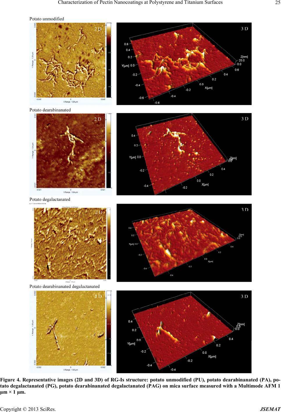 Characterization of Pectin Nanocoatings at Polystyrene and Titanium Surfaces Copyright © 2013 SciRes. JSEMAT 25 Figure 4. Representative images (2D and 3D) of RG-Is structure: potato unmodified (PU), potato dearabinanated (PA), po- tato degalactanated (PG), potato dearabinanated degalactanated (PAG) on mica surface measured with a Multimode AFM 1 μm × 1 μm.  Characterization of Pectin Nanocoatings at Polystyrene and Titanium Surfaces Copyright © 2013 SciRes. JSEMAT 26 Figure 5. Distribution plot of height measurements in nm of RG-Is structure of PU, PA, PG, PAG performed with AFM on Mica surface with 1 μm × 1 μm magnification. Potato unmodified (PU), potato dearabinanated (PA) and potato degalactanated (PG) and potato dearabinanated degalac- tanated (PAG). Figure 6. Representative image (3D) of RG-I nanocoating on aminated titanium implant surface coated with potato dearabinanated (PA aminated Ti implant), magnification 1 × 1 μm, measured using AFM with intermittent “Tapping mode”. Figure 7. Representative confocal images of RG-Is nano- coating visualised with immunofluorescence labeling by pri- mary antibody, anti –(1 → 4)-β-galactan LM5 (IgG2c) and secondary antibody, goat anti-rat IgG for LM5 linked to FITC. Control: aminated Ti implant, Coated: PU Ti im- plant; Ti: titanium, PU: potato unmodified. also to the topographical changes of the surface [25,26]. Our surface roughness results showed that the RG-Is used for nanocoating in general did not significantly af- fect the roughness of the examined surfaces, which is in- Figure 8. Representative confocal images of SaOS-2 cells stained with Vybrant Cell-Labeling Solutions and cultured on Ti implants surface nanocoated with RG-Is. Control: aminated Ti implant, Coated: PU Ti implant; Ti: titanium, PU: potato unmodified. accordance with findings from Morra et al. (2004) [16]. The reason for different results of surface roughness (Sa, Sdr) on polystyrene and titanium surface, when each of the surface groups was compared, can be explained by differences in surface texture, illustrated by the SEM im- ages. It has also to be noticed that the surface roughness was measured by AFM on a 20 µm × 20 µm square area as recommended for a non quantitative overview of the nanotopography [27]. Higher magnification would pro- bably show difference between nanocoated and non- coated surfaces as the RG-I molecules used for coating are around 100 nm in size. Thus, our measurements per- formed with AFM on a 1 µm × 1 µm area clearly visual- ized the RG-Is nanocoating also on the titanium implant surface. Nanocoatings of that size have not previously been demonstrated. The visualization of the nanocoating may be important for characterizing the physical proper- ties of the nanocoated surface. The structure, as well as the distribution and the topography of the nanocoating, may play an important role in cell adhesion, as the nano- coating can mimic the extracellular matrix (ECM) [28]. In the present study, we also visualized RG-Is nanocoat- ing on titanium implants by immunofluorescence stain- ing using the primary LM5 antibody, which specifically binds to galactan side chains. By using the AFM tech- nique with atomically smooth surfaces, we were able to visualize and analyze the height and length of RG-Is from potato. The length of the individual molecule was in the range of 100 nm, which is in agreement with other studies [22]. The height measurements showed a de- crease in the height of modified RG-Is (PA, PG, PAG) compared to unmodified RG-Is (PU), which showed that enzymatic modification changed the RG-Is structure. This corresponds to our previous findings, demonstrating that enzymatic treatment of RG-Is decreases the amount of galactan and arabinan in modified RG-Is compared to unmodified RG-Is (PU). [14] Our height measurements of modified RG-Is have not allowed us to distinguish  Characterization of Pectin Nanocoatings at Polystyrene and Titanium Surfaces Copyright © 2013 SciRes. JSEMAT 27 between dearabinanated, degalactananated and debranch- ed structures and therefore more detailed investigations with AFM in “liquid cell” (AFM imaging in liquids) are necessary [29]. The osteblast-like cells (SaOS2) grown on Ti implants were spread on the surface, however the morphology, cell viability and proliferation studies remain to be per- formed to examine the osteoblast behavior on titanium implant surface coated with RG-Is. On the other hand, our previous studies showed a significant increase in cell viability and matrix mineralization of the same type of cells (SaOS2) on polystyrene and titanium discs surfaces coated with RG-Is containing higher amounts of galac- tose compared to controls [14]. Recent in vitro studies [10,11,14-16] showed that the nanocoating of RG-I with high amounts of galactose enhanced osteoblast spreading and growth, in contrast to the nanocoating of RG-I with high amounts of arabinose, which leads to aggregation and decreased proliferation [11,13,14,16,17]. This find- ing suggests that linear 1.4-linked galactans are impor- tant for osteoblast adhesion, and that high content of ara- binose can shield the galactans, and thus prohibiting their interaction with osteoblasts [30]. It has previously been shown that Galectin-3 binds specifically to galactose residues [31]. As the osteoblastic cells contain Galectin-3, it could therefore be speculated that osteoblast interaction with the RG-I galactans is mediated through Galectin-3. In addition, titanium surfaces coated with RG-Is have been shown to positively influence cell adhesion, mor- phology, proliferation and mineralization [10,15,23]. The positive cell response on plant-derived molecules, espe- cially RG-I with high amount of galactose, opens new direction in the development of organic nanocoatings for biomaterials in order to improve bone healing. 5. Acknowledgements The authors thank Prof. Erik Fink Eriksen from Aarhus Amtssygehus in Denmark for the gift of the SaOS-2 cell line and Marco Morra for the aminated TCPS plates, Ti discs and Ti implants. REFERENCES [1] T. Albrektsson and A. Wennerberg, “Oral Implant Sur- faces: Part 1—Review Focusing on Topographic and Che- mical Properties of Different Surfaces and in Vivo Re- sponses to Them,” The International Journal of Prostho- dontics, Vol. 17, No. 5, 2004, pp. 536-543. [2] T. Albrektsson and A. Wennerberg, “Oral Implant Sur- faces: Part 2—Review Focusing on Clinical Knowledge of Different Surfaces,” The International Journal of Prosthodontics, Vol. 17, No. 5, 2004, pp. 544-564. [3] D. M. Dohan Ehrenfest, P. G. Coelho, B. S. Kang, Y. T. Sul and T. Albrektsson, “Classification of Osseointe- grated Implant Surfaces: Materials, Chemistry and To- pography,” Trends in Biotechnology, Vol. 28, No. 4, 2010, pp. 198-206. http://dx.doi.org/10.1016/j.tibtech.2009.12.003 [4] G. Mendonca, D. B. Mendonca, F. J. Aragao and L. F. Cooper, “Advancing Dental Implant Surface Technol- ogy—From Micron- to Nanotopography,” Biomaterials, Vol. 29, No. 28, 2008, pp. 3822-3835. http://dx.doi.org/10.1016/j.biomaterials.2008.05.012 [5] M. Morra, “Biochemical Modification of Titanium Sur- faces: Peptides and ECM Proteins,” European Cells and Materials Journal, Vol. 12, 2006, pp. 1-15. [6] L. T. de Jonge, S. C. Leeuwenburgh, J. G. Wolke and J. A. Jansen, “Organic-Inorganic Surface Modifications for Ti- tanium Implant Surfaces,” Pharmaceutical Research, Vol. 25, No. 10, 2008, pp. 2357-2369. http://dx.doi.org/10.1007/s11095-008-9617-0 [7] G. L. Le, A. Soueidan, P. Layrolle and Y. Amouriq, “Sur- face Treatments of Titanium Dental Implants for Rapid Osseointegration,” Dental Materials, Vol. 23, No. 7, 2007, pp. 844-854. http://dx.doi.org/10.1016/j.dental.2006.06.025 [8] R. Junker, A. Dimakis, M. Thoneick and J. A. Jansen, “Effects of Implant Surface Coatings and Composition on Bone Integration: A Systematic Review,” Clinical Oral Implants Research, Vol. 20, Suppl. 4, 2009, pp. 185-206. http://dx.doi.org/10.1111/j.1600-0501.2009.01777.x [9] K. Gurzawska, R. Svava, N. R. Jørgensen and K. Got- fredsen, “Nanocoating of Titanium Implant Surfaces with Organic Molecules. Polysaccharides Including Glycosa- minoglycans,” Journal of Biomedical Nanotechnology, Vol. 8, No. 6, 2012, pp. 1012-1024. http://dx.doi.org/10.1166/jbn.2012.1457 [10] H. Kokkonen, C. Cassinelli, R. Verhoef, M. Morra, H. A. Schols and J. Tuukkanen, “Differentiation of Osteoblasts on Pectin-Coated Titanium,” Biomacromolecules, Vol. 9, No. 9, 2008, pp. 2369-2376. http://dx.doi.org/10.1021/bm800356b [11] H. E. Kokkonen, J. M. Ilvesaro, M. Morra, H. A. Schols and J. Tuukkanen, “Effect of Modified Pectin Molecules on the Growth of Bone Cells,” Biomacromolecules, Vol. 8, No. 2, 2007, pp. 509-515. http://dx.doi.org/10.1021/bm060614h [12] A. Wennerberg and T. Albrektsson, “On Implant Surfaces: A Review of Current Knowledge and Opinions,” The In- ternational Journal of Oral & Maxillofacial Implants, Vol. 25, No. 1, 2010, pp. 63-74. [13] C. Bussy, R. Verhoef, A. Haeger, M. Morra, J. L. Duval, P. Vigneron, et al., “Modulating in Vitro Bone Cell and Macrophage Behavior by Immobilized Enzymatically Tailored Pectins,” Journal of Biomedical Materials Re- search Part A, Vol. 86A, No. 3, 2008, pp. 597-606. http://dx.doi.org/10.1002/jbm.a.31729 [14] K. Gurzawska, R. Svava, S. Syberg, Y. Yihua, K. B. Haugshoj, I. Damager, et al., “Effect of Nanocoating with Rhamnogalacturonan-I on Surface Properties and Osteo- blasts Response,” Journal of Biomedical Materials Re- search Part A, Vol. 100, No. 3, 2012, pp. 654-664. http://dx.doi.org/10.1002/jbm.a.33311 [15] H. Kokkonen, H. Niiranen, H. A. Schols, M. Morra, F.  Characterization of Pectin Nanocoatings at Polystyrene and Titanium Surfaces Copyright © 2013 SciRes. JSEMAT 28 Stenback and J. Tuukkanen, “Pectin-Coated Titanium Im- plants Are Well-Tolerated in Vivo,” Journal of Biomedi- cal Materials Research Part A, Vol. 93, No. 4, 2010, pp. 1404-1409. [16] M. Morra, C. Cassinelli, G. Cascardo, M. D. Nagel, C. Della Volpe, S. Siboni, et al., “Effects on Interfacial Pro- perties and Cell Adhesion of Surface Modification by Pectic Hairy Regions,” Biomacromolecules, Vol. 5, No. 6, 2004, pp. 2094-2104. http://dx.doi.org/10.1021/bm049834q [17] M. D. Nagel, R. Verhoef, H. Schols, M. Morra, J. P. Knox, G. Ceccone, et al., “Enzymatically-Tailored Pectins Differ- entially Influence the Morphology, Adhesion, Cell Cycle Progression and Survival of Fibroblasts,” Biochimica et Biophysica Acta, Vol. 1780, No. 7, 2008, pp. 995-1003. [18] A. Wennerberg and T. Albrektsson, “Suggested Guide- Lines for the Topographic Evaluation of Implant Sur- faces,” The International Journal of Oral & Maxillofacial Implants, Vol. 15, No. 3, 2000, pp. 331-344. [19] L. Cheng, P. Fenter, K. L. Nagy, M. L. Schlegel and N. C. Sturchio, “Molecular-Scale Density Oscillations in Water Adjacent to a Mica Surface,” Physical Review Letters, Vol. 87, No. 15, 2001, Article ID: 156103. http://dx.doi.org/10.1103/PhysRevLett.87.156103 [20] T. Matsuura, H. Tanaka, T. Matsumoto and T. Kawai, “Ato- mic Force Microscopic Observation of Escherichia coli Ribosomes in Solution,” Bioscience, Biotechnology, and Biochemistry, Vol. 70, No. 1, 2006, pp. 300-302. http://dx.doi.org/10.1271/bbb.70.300 [21] C. H. Lui, L. Liu, K. F. Mak, G. W. Flynn, T. F. Heinz, “Ultraflat Graphene,” Nature, Vol. 462, No. 7271, 2009, pp. 339-341. http://dx.doi.org/10.1038/nature08569 [22] K. T. Inngjerdingen, T. R. Patel, X. Chen, L. Kenne, S. Allen, G. A. Morris, et al., “Immunological and Struc- tural Properties of a Pectic Polymer from Glinus oppose- tifolius,” Glycobiology, Vol. 17, No. 12, 2007, pp. 1299- 1310. http://dx.doi.org/10.1093/glycob/cwm088 [23] K. A. Gurzawska, R. Svava, Y. Yihau Dr., K. B. Haug- shøj, K. Dirscherl, S. B. Levery, I. Byg, I. Damager, B. Jørgensen, N. R. Jørgensen and K. Gotfredsen, “Os- teoblastic Response to Pectin Nanocoating of Titanium Surface,” Submitted, under Review. [24] S. Tajima, J. S. Chu, S. Li and K. Komvopoulos, “Dif- ferential Regulation of Endothelial Cell Adhesion, Spread- ing, and Cytoskeleton on Low-Density Polyethylene by Nanotopography and Surface Chemistry Modification In- duced by Argon Plasma Treatment,” Journal of Biomedi- cal Materials Research Part A, Vol. 84, No. 3, 2008, pp. 828-836. http://dx.doi.org/10.1002/jbm.a.31539 [25] F. Rupp, L. Scheideler, N. Olshanska, M. de Wild, M. Wieland and J. Geis-Gerstorfer, “Enhancing Surface Free Energy and Hydrophilicity through Chemical Modifica- tion of Microstructured Titanium Implant Surfaces,” Jour- nal of Biomedical Materials Research Part A, Vol. 76A, No. 2, 2006, pp. 323-334. http://dx.doi.org/10.1002/jbm.a.30518 [26] S. Tosatti, M. Textor and N. D. Spencer, “Self-Assem- bled Monolayer of Dodecyl and Hydroxy-Dodecyl Phos- phate at Smooth and Rough Titanium and Titanium Ox- ide Surfaces,” Langmuir, Vol. 18, No. 9, 2002, pp 3537- 3548. [27] A. Bagno and B. C. Di, “Surface Treatments and Rough- ness Properties of Ti-Based Biomaterials,” Journal of Ma- terials Science: Materials in Medicine, Vol. 15, No. 9, 2004, pp. 935-949. http://dx.doi.org/10.1023/B:JMSM.0000042679.28493.7f [28] F. Munarin, S. G. Guerreiro, M. A. Grellier, M. C. Tanzi, M. A. Barbosa, P. Petrini, et al., “Pectin-Based Injectable Biomaterials for Bone Tissue Engineering,” Biomacro- molecules, Vol. 12, No. 3, 2011, pp. 568-577. http://dx.doi.org/10.1021/bm101110x [29] V. J. Morris, A. Gromer, A. R. Kirby, R. J. M. Bongaerts and A. Patrick Gunning, “Using AFM and Force Spec- Troscopy to Determine Pectin Structure and (bio) Func- tionality,” Food Hydrocolloids, Vol. 25, No. 2, 2011, pp. 230-237. http://dx.doi.org/10.1016/j.foodhyd.2009.11.015 [30] H. Kokkonen, R. Verhoef, K. Kauppinen, V. Muhonen, B. Jorgensen, I. Damager, et al., “Affecting Osteoblastic Res- ponses with in Vivo Engineered Potato Pectin Frag- ments,” Journal of Biomedical Materials Research Part A, Vol. 100A, No. 1, 2012, pp. 111-119. http://dx.doi.org/10.1002/jbm.a.33240 [31] A. P. Gunning, R. J. Bongaerts and V. J. Morris, “Recog- nition of Galactan Components of Pectin by Galectin-3,” The FASEB Journal, Vol. 23, No. 2, 2009, pp. 415-424. http://dx.doi.org/10.1096/fj.08-106617
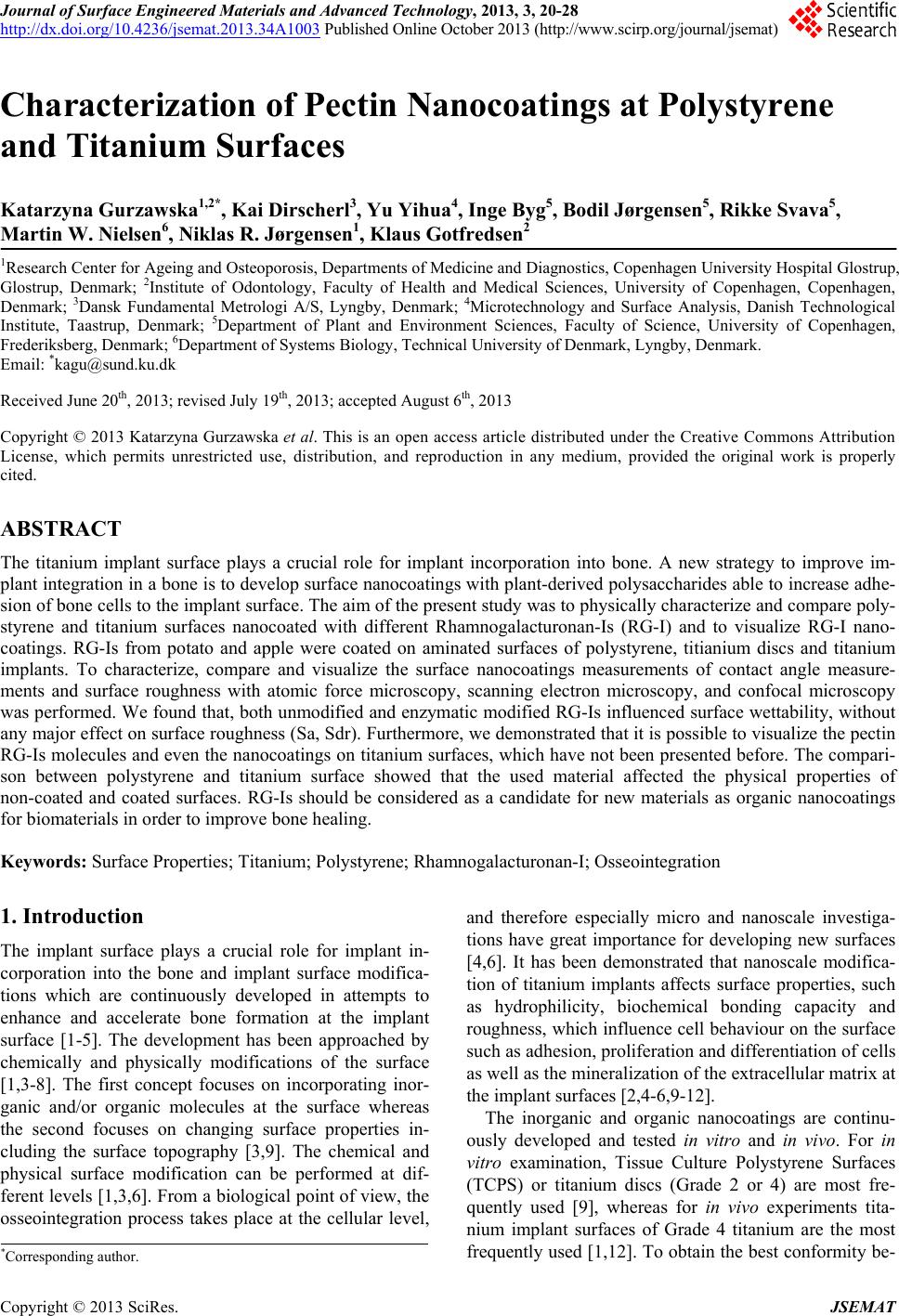
|