 Journal of Signal and Information Processing, 2013, 4, 91-95 doi:10.4236/jsip.2013.43B016 Published Online August 2013 (http://www.scirp.org/journal/jsip) 91 Optimal Design for MIMO Relay System Fangni Chen Department of Communication and Electronic Engineering, Zhejiang University of Science and Technology, Hangzhou, China. Email: cfnini@163.com Received May, 2013. ABSTRACT Recently, multiple-input multiple-output (MIMO) relay technique has been received great attention due to its prominent ability to provide broad coverage and enhance the link reliability and spectral efficiency. In this paper, an overview of optimal design for single user and multiuser non-regenerative MIMO relay systems is propos ed. We explore some key designs of source node and destination node as well as relay node processing matrices using minimum mean square error (MMSE) criterion under the transmit power constraints. Simulation resu lts compare different methods in terms of the MSE and bit error rate (BER) performance. Keywords: MIMO; Relay; Optimal Design; MMSE 1. Introduction Multiple-input multiple-output (MIMO) relay communi- cation, which incorporates relaying technology in MIMO network, has attracted considerable attention in recent years due to its potential ability to extend network cov- erage and improve link reliability as well as spectral effi- ciency. The aim of this paper is to provide an overview of optimal design for single user non-regenerative MIMO relay systems. A MIMO relay can be regenerative or non-regenera- tive, full-duplex or half-duplex, one-way or two-way [1]. A regenerative relay requires digital decoding and re- encoding at the relay, which can cause a significant in- crease of delay and complexity. A non-regenerative relay does not need any digital decoding and re-encoding at the relay, which is a useful advantage over regenerative re- lays. The difference between full-duplex relay and half- duplex relay depends on whether relays can transmit and receive in the same time or same frequency or not. Full- duplex relay is spectrally efficient but causes a problem of self-interference and half-duplex relay is easy to im- plement but not spectrally efficient as full-duplex. The difference between two-way relay and one-way relay is whether relays can relay information in two directions in a single time or single frequ ency or not. In this paper we will focus on non-regenerative, half-duplex, one-way MIMO relay systems. Initial research on MIMO relay began in single user [2], where the capacity bounds of MIMO relay systems were examined. It has been shown in [3] and [4] that performing linear processing at the relay node can out- perform the conventional AF relaying in a non-regenera- tive, also known as amplify-and-forward (AF), MIMO relay system. The optimal relay amplifying matrix which maximizes the mutual information (MI) between source and destination is derived in [5]. In [6], a minimum mean square error (MMSE)-based iterative algorithm is pro- posed for jointly designing the source, relay and destina- tion processing matrices. A unified framework is devel- oped in [7] to jointly optimize the source preceding ma- trix and the relay amplifying matrix for a broad class of objective functions. In this paper, we focus on optimization for single user non-regenerative MIMO relay systems where each node is equipped with multiple antennas supporting multiple data streams. We explore two design schemes to opti- mize the transmitter and receiver aiming at minimizing the MSE. First we introduce an iterative algorithm to find the optimal source preceding matrix and relay amplifying matrix. Considering the complexity in practical applica- tions, we also introduce the simplified algorithm to solve the same optimization problem. Simulation results show the simplified algorithm has a comparable performance with the iterative one. The rest of this paper is organized as follows. In Sec- tion II, we introduce the single user non-regenerative MIMO relay system model and formulate the optimiza- tion problem. Different optimization methods of obtain- ing the source preceding matrix and relay amplifying matrix structure under power constraints are analyzed in section III. Simulation results are conducted to compare the system performances of the different methods in Sec- tion IV. Finally, extensions and future work are drawn in Copyright © 2013 SciRes. JSIP 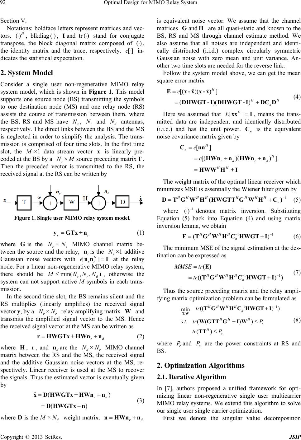 Optimal Design for MIMO Relay System 92 Section V. Notations: boldface letters represent matrices and vec- tors. () , blkdiag, and tr stand for conjugate transpose, the block diagonal matrix composed of ()I()() , the identity matrix and the trace, respectively. []e in- dicates the statistical expectation. 2. System Model Consider a single user non-regenerative MIMO relay system model, which is shown in Figure 1. This model supports one source node (BS) transmitting the symbols to one destination node (MS) and one relay node (RS) assists the course of transmission between them, where the BS, RS and MS have N, r and d antennas, respectively. The direct links between the BS and the MS is neglected in order to simplify the analysis. The trans- mission is comprised of four time slots. In the first time slot, the N N ×1 data stream vector is linearly pre- coded at the BS by a x N× source preceding matrixT. Then the preceded vector is transmitted to the RS, the received signal at the RS can be written by Figure 1. Single user MIMO relay system model. r yGTx+n r (1) where is the r×GN N min MIMO channel matrix be- tween the source and the relay, is the r×1 additive Gaussian noise vectors with at the relay node. For a linear non-regenerative MIMO relay system, there should be r n [ enn , N ] I H rr , )( rd NNN, otherwise the system can not support active M symbols in each trans- mission. In the second time slot, the BS remains silent and the RS multiplies (linearly amplifies) the received signal vector r by a r×r relay amplifying matrix and transmits the amplified signal vector to the MS. Hence the received signal vector at the MS can be written as N NW d r rHWGTx+HWn n ) (2) where , , and dare the d×r MIMO channel matrix between the RS and the MS, the received signal and the additive Gaussian noise vectors at the MS, re- spectively. Linear receiver is used at the MS to recover the signals. Thus the estimated vector is eventually given by Hr nN N ˆ( () rd xDHWGTx + HWnn DHWGTx n (3) where D is the M × weight matrix. is equivalent noise vector. We assume that the channel matrices and are all quasi-static and known to the BS, RS and MS through channel estimate method. We also assume that all noises are independent and identi- cally distributed (i.i.d.) complex circularly symmetric Gaussian noise with zero mean and unit variance. An- other two time slots are needed for the reverse link. d Nrd nHWn n G [( H )( Follow the system model above, we can get the mean square error matrix ˆˆ) ] ()() H H n e --x DHWGT - IDHWGT - IDCD Ex n xx [( H (4) Here we assumed that , means the trans- mitted data are independent and identically distributed (i.i.d.) and has the unit power. is the equivalent noise covariance matrix given by [] H Exx I n C [] )() ] rd rd HH e n HWnn HWnn HWWH+ I e Cn H HH The weight matrix of the optimal linear receiver which minimizes MSE is essentially the Wiener filter given by 1 ( HHH HHn D THWGTTGWHC)GW () H (5) where 1 denotes matrix inversion. Substituting Equation (5) back into Equation (4) and using matrix inversion lemma, we obtain 11 () HH HH n WHCHWGTI E MMSE T G (( tr (6) The minimum MSE of the signal estimation at the des- tination can be expressed as 11 () ) ) HH HH n tr E TGWHCHWGT I (7) Thus the source preceding matrix and the relay ampli- fying matrix optimization problem can be formulated as 11 ) ) ) ) () HH HH n HHH r Hs t P tr P TGWHCHWGT I GTTG+ IW (( ( tr rW( TT min ..st T,W r (8) where and P P are the power constraints at RS and BS. 2. Optimization Algorithms 2.1. Iterative Algorithm In [7], authors proposed a unified framework for opti- mizing linear non-regenerative single user multicarrier MIMO relay systems. We extend this algorithm to solve our single user single carrier optimization. First we denote the singular value decomposition Copyright © 2013 SciRes. JSIP 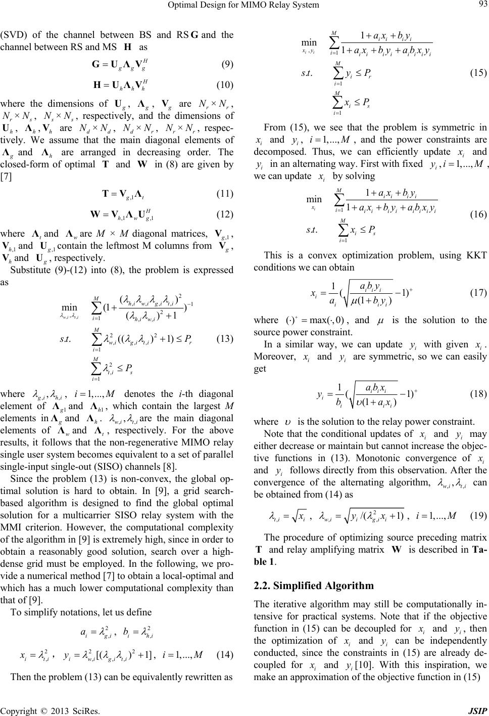 Optimal Design for MIMO Relay System 93 (SVD) of the channel between BS and RSand the channel between RS and MS as G H gg GUΛV (9) hhh HUΛV (10) where the dimensions of U, Λ, V are r×r, ×N N r N N, N× N, respectively, and the dimensions of h, h,h are d×d, d×r, r×r, respec- tively. We assume that the main diagonal elements of UΛVN NNNNN Λand h are arranged in decreasing order. The closed-form of optimal and in (8) are given by [7] Λ TW ,1 t TVΛ (11) ,1 ,1 hwg WVΛU (12) where and ware M × M diagonal matrices, t Λ Λ,1 V, and ,1,1h V Ucontain the leftmost M columns from V, and h V U, respectively. Substitute (9)-(12) into (8), the problem is expressed as ,, 2 ,,,, 1 2 ,1,, 22 ,,, 1 2 , 1 () min (1) ()1 ..(() 1) wi ti Mhi wigi ti ihi wi M wigi tir i M ti s i t P P (13) where ,, , ihi , denotes the i-th diagonal element of 1 1,...,iM Λand 1, which contain the largest M elements inh Λ Λand . ,,ti h Λwi, are the main diagonal elements of wand t, respectively. For the above results, it follows that the non-regenerative MIMO relay single user system becomes equivalent to a set of parallel single-input single-out (SISO) channels [8]. Λ Λ Since the problem (13) is non-convex, the global op- timal solution is hard to obtain. In [9], a grid search- based algorithm is designed to find the global optimal solution for a multicarrier SISO relay system with the MMI criterion. However, the computational complexity of the algorithm in [9] is extremely high, since in order to obtain a reasonably good solution, search over a high- dense grid must be employed. In the following, we pro- vide a numerical method [7] to obtain a local-optimal and which has a much lower computational complexity than that of [9]. To simplify notations, let us define 2,ig ai , i 2,ih b 2 ,it xi ,, (14) 22 ,,, [() 1] iwigiti y 1,...,iM Then the problem (13) can be equivalently rewritten as ,1 1 1 1 min 1 .. ii Mii ii xy iii iiiiii M ir i M is i ax by ax byabxy sty P xP (15) From (15), we see that the problem is symmetric in i and i, y1,...,iM , and the power constraints are decomposed. Thus, we can efficiently update i and i in an alternating way. First with fixed ,yi y1, ...,iM , we can update i by solving 1 1 1 min 1 .. i Mii ii xiiiiiiiii M is i ax by ax byabxy stxP (16) This is a convex optimization problem, using KKT conditions we can obtain 1( (1 ) ii i i iii aby xaby 1 ) (17) where () max(,0) , and is the solution to the source power constraint. In a similar way, we can update i with given i y . Moreover, i and are symmetric, so we can easily get i y 1( (1 ) iii i iii abx ybax 1 ) (18) where is the solution to the relay power constraint. Note that the conditional updates of i and i may either decrease or maintain but cannot increase the objec- tive functions in (13). Monotonic convergence of i y and i follows directly from this observation. After the convergence of the alternating algorithm, y , ,ti,wi can be obtained from (14) as ,ti i , 2 ,, /( 1) wiigi i yx , (19) 1,...,iM The procedure of optimizing source preceding matrix and relay amplifying matrix is described in Ta- ble 1. TW 2.2. Simplified Algorithm The iterative algorithm may still be computationally in- tensive for practical systems. Note that if the objective function in (15) can be decoupled for i and i, then the optimization of i y and i can be independently conducted, since the constraints in (15) are already de- coupled for i y and i[10]. With this inspiration, we make an approximation of the objective function in (15) y Copyright © 2013 SciRes. JSIP 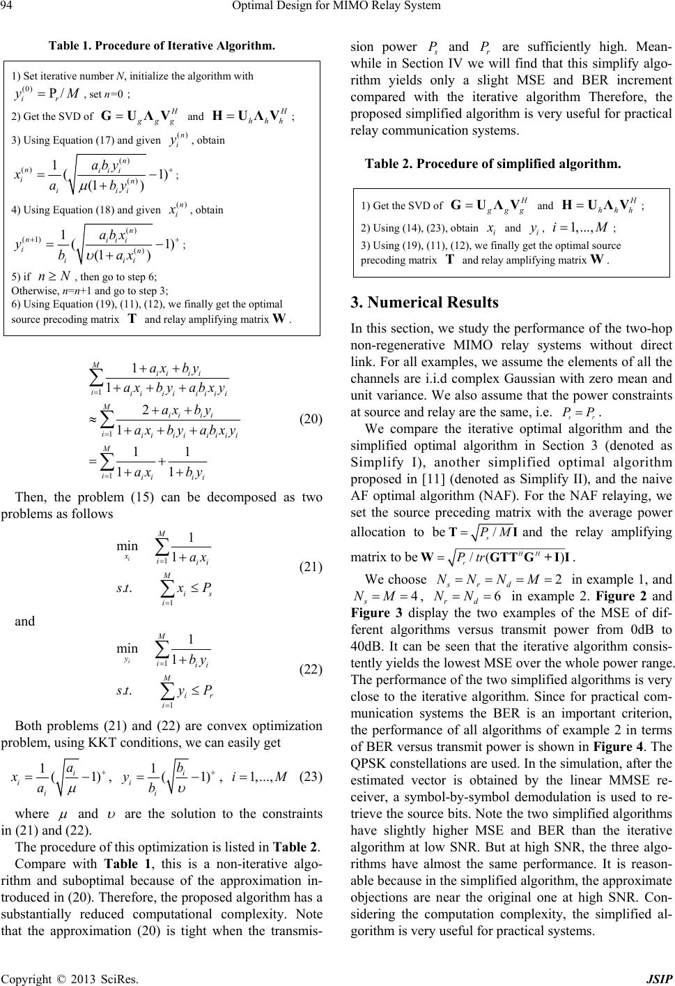 Optimal Design for MIMO Relay System 94 Table 1. Procedure of Iterative Algorithm. 1) Set iterative number N, initialize the algorithm with , set n=0; (0) P/ ir yM 2) Get the SVD of gg GUΛV and hhh HUΛV; 3) Using Equation (17) and giv en , obtain ()n i y () () () 1(1 (1 ) n nii i in iii aby xaby ) ; 4) Using Equation (18) and giv en ()n i , obtain () (1) () 1(1 ) (1 ) n niii in iii abx ybax ; 5) if , then go to step 6; nN Otherwise, n=n+1 and go to step 3; 6) Using Equation (19), (11), (12), we finally get the optimal source precoding matrix and relay amplifying matrix. T W 1 1 1 1 1 2 1 11 11 Mii ii iii iiiiii Mii ii iiiiiiiii M iii ii ax by ax byabxy ax by ax by abxy ax by (20) Then, the problem (15) can be decomposed as two problems as follows 1 1 1 min 1 .. i M xiii M is i ax tx P (21) and 1 1 1 min 1 .. i M yiii M ir i by ty P (22) Both problems (21) and (22) are convex optimization problem, using KKT conditions, we can easily get 1(1) i i i a xa , 1(1) 1,...,i i i i b yb M, (23) where and are the solution to the constraints in (21) and (22). The procedure of this optimization is listed in Table 2. Compare with Table 1, this is a non-iterative algo- rithm and suboptimal because of the approximation in- troduced in (20). Therefore, the proposed algorithm has a substantially reduced computational complexity. Note that the approximation (20) is tight when the transmis- sion power P and r are sufficiently high. Mean- while in Section IV we will find that this simplify algo- rithm yields only a slight MSE and BER increment compared with the iterative algorithm Therefore, the proposed simplified algorithm is very useful for practical relay communication systems. P Table 2. Procedure of simplified algorithm. 1) Get the SVD of gg GUΛV and hhh HUΛV; 2) Using (14), (23), obtain i and , ; i y1,...,iM 3) Using (19), (11), (12), we finally get the optimal source precoding matrix and relay amplifying matrix. T W 3. Numerical Results In this section, we study the performance of the two-hop non-regenerative MIMO relay systems without direct link. For all examples, we assume the elements of all th e channels are i.i.d complex Gaussian with zero mean and unit variance. We also assume that the power constraints at source and relay are the same, i.e. r We compare the iterative optimal algorithm and the simplified optimal algorithm in Section 3 (denoted as Simplify I), another simplified optimal algorithm proposed in [11] (denoted as Simplify II), and the naive AF optimal algorithm (NAF). For the NAF relaying, we set the source preceding matrix with the average power PP. allocation to be/ s PMTIand the relay amplifying matrix to be/( ) HH r PtrWGTTG+II. We choose 2 srd NNNM in example 1, and 4 s NM , 6 rd NN in example 2. Figure 2 and Figure 3 display the two examples of the MSE of dif- ferent algorithms versus transmit power from 0dB to 40dB. It can be seen that the iterative algorithm consis- tently yields the lowest MSE over the whole power range. The performance of the two simplified algorithms is very close to the iterative algorithm. Since for practical com- munication systems the BER is an important criterion, the performance of all algorithms of example 2 in terms of BER versus transmit power is shown in Figure 4. The QPSK constellations are used. In the simulation , after the estimated vector is obtained by the linear MMSE re- ceiver, a symbol-by-symbol demodulation is used to re- trieve the source bits. Note the two simplified algorithms have slightly higher MSE and BER than the iterative algorithm at low SNR. But at high SNR, the three algo- rithms have almost the same performance. It is reason- able because in the simplified alg orithm, the approximate objections are near the original one at high SNR. Con- sidering the computation complexity, the simplified al- gorithm is very useful for practical systems. Copyright © 2013 SciRes. JSIP 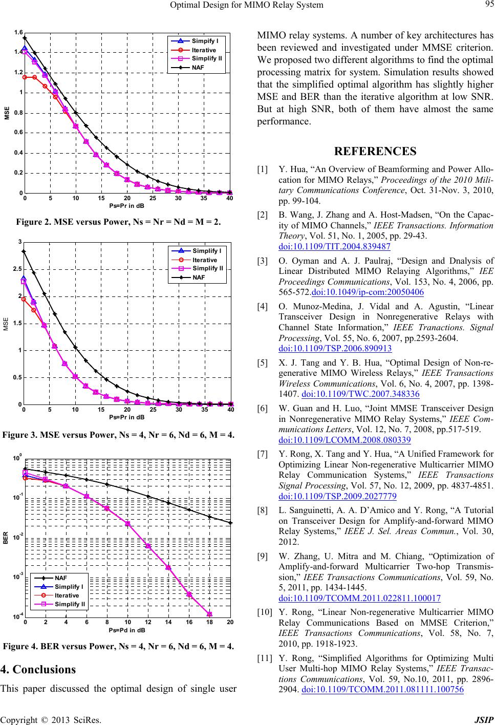 Optimal Design for MIMO Relay System Copyright © 2013 SciRes. JSIP 95 05 10 1520 25 30 35 40 0 0. 2 0. 4 0. 6 0. 8 1 1. 2 1. 4 1. 6 Ps=Pr in dB MSE Simpify I Iterative Simplify II NAF Figure 2. MSE versus Power, Ns = Nr = Nd = M = 2. 0510 1520 25 3035 40 0 0.5 1 1.5 2 2.5 3 Ps=Pr in dB MSE Simplify I Iterative Simplify II NAF Figure 3. MSE versus Power, Ns = 4, Nr = 6, Nd = 6, M = 4. 0 2 46 810 12 141618 20 10 -4 10 -3 10 -2 10 -1 10 0 Ps=Pd in dB BER NAF Simplify I Iterative Simplify II Figure 4. BER versus Power, Ns = 4, Nr = 6, Nd = 6, M = 4. 4. Conclusions This paper discussed the optimal design of single user MIMO relay systems. A number of key architectures has been reviewed and investigated under MMSE criterion. We proposed two different alg orithms to find the opti mal processing matrix for system. Simulation results showed that the simplified optimal algorithm has slightly higher MSE and BER than the iterative algorithm at low SNR. But at high SNR, both of them have almost the same performance. REFERENCES [1] Y. Hua, “An Overview of Beamforming and Power Allo- cation for MIMO Relays,” Proceedings of the 2010 Mili- tary Communications Conference, Oct. 31-Nov. 3, 2010, pp. 99-104. [2] B. Wang, J. Zhang and A. Host-Madsen, “On the Capac- ity of MIMO Channels,” IEEE Transactions. Information Theory, Vol. 51, No. 1, 2005, pp. 29-43. doi:10.1109/TIT.2004.839487 [3] O. Oyman and A. J. Paulraj, “Design and Dnalysis of Linear Distributed MIMO Relaying Algorithms,” IEE Proceedings Communications, Vol. 153, No. 4, 2006, pp. 565-572.doi:10.1049/ip-com:20050406 [4] O. Munoz-Medina, J. Vidal and A. Agustin, “Linear Transceiver Design in Nonregenerative Relays with Channel State Information,” IEEE Tranactions. Signal Processing, Vol. 55, No. 6, 2007, pp.2593-2604. doi:10.1109/TSP.2006.890913 [5] X. J. Tang and Y. B. Hua, “Optimal Design of Non-re- generative MIMO Wireless Relays,” IEEE Transactions Wireless Communications, Vol. 6, No. 4, 2007, pp. 1398- 1407. doi:10.1109/TWC.2007.348336 [6] W. Guan and H. Luo, “Joint MMSE Transceiver Design in Nonregenerative MIMO Relay Systems,” IEEE Com- munications Letters, Vol. 12, No. 7, 2008, pp.517-519. doi:10.1109/LCOMM.2008.080339 [7] Y. Rong, X. Tang and Y. Hua, “A Unified Framework for Optimizing Linear Non-regenerative Multicarrier MIMO Relay Communication Systems,” IEEE Transactions Signal Processing, Vol. 57, No. 12, 2009, pp. 4837-4851. doi:10.1109/TSP.2009.2027779 [8] L. Sanguinetti, A. A. D’Amico and Y. Rong, “A Tutorial on Transceiver Design for Amplify-and-forward MIMO Relay Systems,” IEEE J. Sel. Areas Commun., Vol. 30, 2012. [9] W. Zhang, U. Mitra and M. Chiang, “Optimization of Amplify-and-forward Multicarrier Two-hop Transmis- sion,” IEEE Transactions Communications, Vol. 59, No. 5, 2011, pp. 1434-1445. doi:10.1109/TCOMM.2011.022811.100017 [10] Y. Rong, “Linear Non-regenerative Multicarrier MIMO Relay Communications Based on MMSE Criterion,” IEEE Transactions Communications, Vol. 58, No. 7, 2010, pp. 1918-1923. [11] Y. Rong, “Simplified Algorithms for Optimizing Multi User Multi-hop MIMO Relay Systems,” IEEE Transac- tions Communications, Vol. 59, No.10, 2011, pp. 2896- 2904. doi:10.1109/TCOMM.2011.081111.100756
|