Paper Menu >>
Journal Menu >>
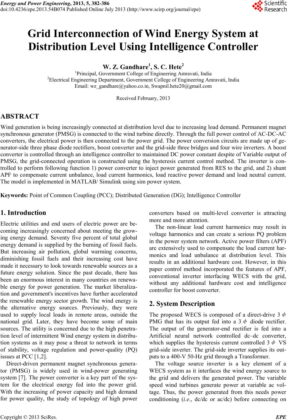 Energy and Power E ngineering, 2013, 5, 382-386 doi:10.4236/epe.2013.54B074 Published Online July 2013 (http://www.scirp.o rg/journal/epe) Copyright © 2013 SciRes. EPE Grid Interconnection of Wind Energy System at Distribution Level Using Intelligence Controller W. Z. Gandhare1, S. C. Hete2 1Principal, Government College of Engineering Amravati, India 2Electri cal Engineer ing Depart ment, Government College of Engineering Amravati, India Email: wz_gandhare@yahoo.co.in, Swapnil.hete20@gmail.com Received February, 2013 ABSTRACT Wind generation is being increasingly connected at distribution level due to increasing load demand. Permanent magnet synchronous generator (PM S G) is connected to the wind turbine directly. Through the full power control of AC-DC-AC converters, the electrical power is then connected to the power grid. The power conversion circuits are made up of ge- nerator-side three phase diode rectifiers, boost converter and the gri d-side three bridges and four wire inverter s. A boost converter is controlle d throu gh an inte lligence c ontrolle r to mai ntai ned DC power constant d espite of Variab le o utput of PMSG, the grid-connected operation is constructed using the hysteresis current control method. The inverter is con- trolled to perform follo wing function 1) power converter to inject power generated from RES to the grid, and 2) shunt APF to compensate current unbalance, load current harmonics, load reactive power demand and load neutral current. The model is implemented in M ATLAB/ Simulink using sim power system. Keywords: Point of Common Coupling (PCC); Distrib uted Generatio n (D G ); Intelligence Controller 1. Introduction Electric utilities and end users of electric power are be- coming increasingly concerned about meeting the grow- ing energy demand. Seventy five percent of total global ener gy de mand i s supp lied b y the b urni ng of fossil fuel s. But increasing air pollution, global warming concerns, diminishing fossil fuels and their increasing cost have made it necessary to look towards renewable sources as a future energy solution. Since the past decade, there has been an enormous interest in many countries on renewa- ble energy for power generation. The market liberaliza- tion a nd gover nment's incentives have further accelerated the renewable energy sector growth. The wind energy is the alternative energy sources. Previously, they were used to supply local loads in remote areas, outside the national grid. Later, they have become some of main sourc es. The utility is co ncerne d due to the hi gh penetra- tion level of i ntermittent W ind energ y system in distrib u- tion systems as it may pose a threat to network in terms of stability, voltage regulation and power-quality (PQ) issues a t PCC [1,2]. Direct-driven permanent magnet synchronous genera- tor (PMSG) is widely used in wind-power generating system [7]. The power converter is a key part of the sys- tem for the electrical energy fed into the power grid. With the i ncreasing of power capacity and high demand for power quality, the study of topology of high power converters based on multi-level converter is attracting more and more attention. The non-linear load current harmonics may result in voltage harmonics and can create a serious PQ problem in the power system network. Active power filters (APF) are extensively used to compensate the load current har- monics and load unbalance at distribution level. This results in an additional hardware cost. However, in this paper control method incorporated the features of APF, conventional inverter interfacing WECS with the grid, without any additional hardware cost and intelligence controller for boost converter. 2. System Description The proposed WECS is composed of a direct-drive 3 φ PMG that has its output fed into a 3 φ diode rectifier. The output of the generator-end rectifier is fed into a Artificial neural network controlled dc–dc converter, which supplies the hysteresis current controlled 3 φ VS grid-side inverter. The grid-side inverter supplies its out- puts to a 400-V 50-Hz grid through a Transformer. The voltage source inverter is a key element of a WECS system as it interfaces the wind energy source to the grid and delivers the generated power. The variable speed wind turbines generate power at variable ac vol- tage. Thus, the power generated from this needs power conditioning (i.e ., dc/dc or ac/dc) before connecting on  W. Z. GANDHARE, S. C. HETE Copyright © 2013 SciRes. EPE 383 dc-link. Figure 1 shows General Scheme of the wind ener gy conversi on syste m Figure 1. General Scheme of the Wind Energy Conversion System. 3. Intelligence Controller for Boost Converter The control of a dc–dc converter employed in PMG based WECS can be established to achieve the following goals [3,4]. 1) To maintain a close-to-fixed d c input voltage to the grid side inverter under wind speed variations as well as under changes in the output power (P and/or Q) of the grid-side inverter; 2) To supply energy to the grid-side inverter during transient changes in the wind speed. The goals of controlling the dc–dc converter can be achieved through adjusting its duty cycle by following formula which regulates the dc output voltage of the ge- nerator-end rectifier using artificial intelligence network. Output voltage is step-up and maintained constant using equation 1 1 O i V VD =− Where, Vo - Output voltage of boost converter Vi - Input voltage of boost converter D – Duty ratio of boost converter The duty ratio of the bo ost converter is varied to com- pensate the variations in the input voltage. Therefore output voltage is kept at a d esired value. Con trol strate gy for closed loop DC-DC boost converter is shown in Fig- ure 2. Here output voltage is sensed and is compared with a set reference voltage. The error is processed through a intelligence controller whose output is used to modulate the pulses that drive the IGBT gate. Gate sig- nals of IGBT are generated by PWM by comparing a carrier signal with the signal generated by intelligence controller. We have developed a feed-forward network which is trained by back propagation algorithm. The simplest way to generate a PWM signal is the intercep- tive method, which requires only a saw tooth or a trian- gular waveform and a comparator. Figure 2 . Simulink Mo del of Boost C onve r ter. Figure 3. Programme to develop feed-forward network in MATLAB. When the value of the reference signal is more than the mod ulat ion wa vefor m, the PWM signal is i n the hi gh state, other wise it is in t he lo w state [ 5] . Figure 3. S hows programmed to develop Feed forward network in MATLAB 4. Control of Grid Interfacing Inverter TBFW inverter incorporates the features of APF in the conventional interfacing inverter. The inverter can per- form the following functions: 1) Transfer of active power from the generator to the load/grid 2) Reactive power demand support 3) Current unbalance, cur rent harmonics compensation With adequate control of grid-interfacing inverter, all the objectives can be accomplished either individually or simultaneously. The Power quality constraints can there- fore be strictly maintained within the utility standards 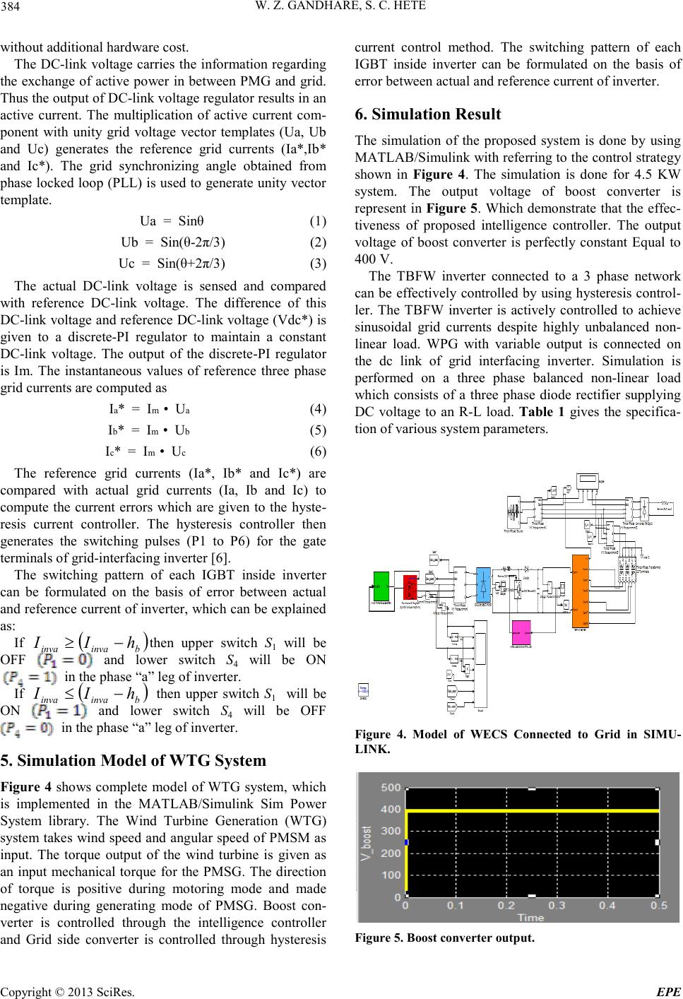 W. Z. GANDHARE, S. C. HETE Copyright © 2013 SciRes. EPE 384 without add itional hardware cost. The DC-link voltage carries the information regarding the exchange of active power in between PMG and grid. Thus t he o utp ut o f D C -link volta ge r e gul at or r esul ts i n a n active current. The multiplication of active current com- ponent with unity grid voltage vector templates (Ua, Ub and Uc) generates the reference grid currents (Ia*,Ib* and Ic*). The grid synchronizing angle obtained from phase locked loop (PLL) is used to generate unity vector template. Ua = Sinθ (1) Ub = Sin(θ-2π/3) (2) Uc = Sin(θ+2π/3) (3) The actual DC-link voltage is sensed and compared with reference DC-link voltage. The difference of this DC-link voltage and r efere nce DC -link voltage (Vdc *) is given to a discrete-PI regulator to maintain a constant DC-link voltage. The output of the discrete-PI regulator is Im. The instantaneous values of reference three phase grid currents are computed as Ia* = Im • Ua (4) Ib* = Im • Ub (5) Ic* = Im • Uc (6) The reference grid currents (Ia*, Ib* and Ic*) are compared with actual grid currents (Ia, Ib and Ic) to compute the current errors which are given to the hyste- resis current controller. The hysteresis controller then generates the switching pulses (P1 to P6) for the gate terminals of grid-interfacing inverter [6]. The switching pattern of each IGBT inside inverter can be formulated on the basis of error between actual and reference current of inverter, which can be explained as: If ( ) binvainva hII −≥ then upper switch S1 will be OFF and lower switch S4 will be ON in the phase “a” leg of inverter. If ( ) binvainva hII −≤ then upper switch S1 will be ON and lower switch S4 will be OFF in the phase “a” leg of inverter. 5. Simulation Model of WTG System Figure 4 shows complete model of WTG system, which is implemented in the MATLAB/Simulink Sim Power System library. The Wind Turbine Generation (WTG) system takes wind speed and angular speed of PMSM as input. The torque output of the wind turbine is given as an input mechanical torque for the PMSG. The direction of torque is positive during motoring mode and made negative during generating mode of PMSG. Boost con- verter is controlled through the intelligence controller and Grid side converter is controlled through hysteresis current control method. The switching pattern of each IGBT inside inverter can be formulated on the basis of error between actual and reference current of inverter. 6. Simulation Result The simulation of the proposed system is done by using MATLAB/Si mulink wit h referring to t he control strate g y shown in Figure 4. The simulation is done for 4.5 KW system. The output voltage of boost converter is represent in Figure 5. Which demonstrate that the effec- tiveness of proposed intelligence controller. The output voltage of boost converter is perfectly constant Equal to 400 V. The TBFW inverter connected to a 3 phase network can be effectively controlled by using hysteresis control- ler. The TBFW inverter is actively controlled to achieve sinusoidal grid currents despite highly unbalanced non- linear load. WPG with variable output is connected on the dc link of grid interfacing inverter. Simulation is performed on a three phase balanced non-linear load which consists of a three phase diode rectifier supplying DC voltage to an R-L load. Table 1 gives the specifica- tion of various system parameters. Figure 4. Model of WECS Connected to Grid in SIMU- LINK. Figure 5 . Boost converter output. 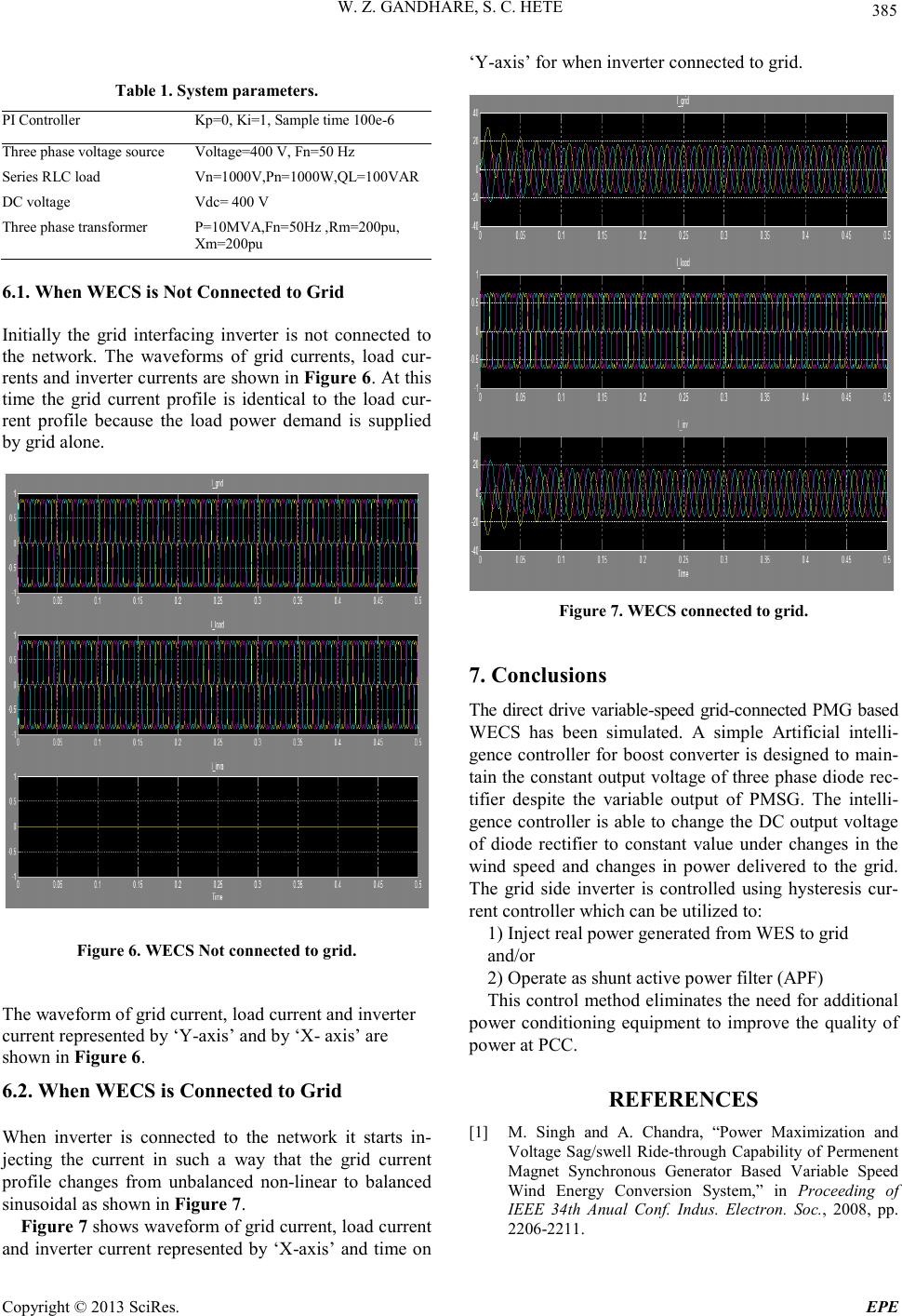 W. Z. GANDHARE, S. C. HETE Copyright © 2013 SciRes. EPE 385 Table 1. Sys te m parameters. PI Controller Kp=0, Ki=1, Sample time 100e-6 Three pha se voltage sour ce Voltage=400 V, Fn=50 Hz Series RLC lo ad Vn=1000V,Pn=1000W,QL=100VAR DC volta ge Vdc= 400 V Three pha se transformer P=10MVA,Fn=50Hz ,Rm=200pu, Xm=200pu 6.1. When WECS is Not Connecte d to Grid Initially the grid interfacing inverter is not connected to the network. The waveforms of grid currents, load cur- rents a nd i nver ter c urr ents a re sho wn in Figure 6. At this time the grid current profile is identical to the load cur- rent profile because the load power demand is supplied by grid alone. Figure 6 . WECS Not connecte d to grid. The waveform of grid c urrent, load c urrent and inverter current represented by ‘Y-axis’ and by ‘X- axis’ are sho wn in Figure 6. 6.2. When WECS is Connected to Grid When inverter is connected to the network it starts in- jecting the current in such a way that the grid current profile changes from unbalanced non-linear to balanced sinusoidal as shown in Figure 7. Figure 7 sho ws wave fo rm of gri d cur re nt, lo a d current and inverter current represented by ‘X-axis’ and time on ‘Y-axis’ for when inverter connected to grid. Figure 7 . WECS connected to grid. 7. Conclusions The direct drive variable-speed grid-connected PMG based WECS has been simulated. A simple Artificial intelli- gence controller for boost converter is designed to main- tain the constant o utput volta ge of three phase dio de rec- tifier despite the variable output of PMSG. The intelli- gence controller is able to change the DC output voltage of diode rectifier to constant value under changes in the wind speed and changes in power delivered to the grid. The grid side inverter is controlled using hysteresis cur- rent controller which can be utilized to: 1) Inject real power generated fro m WES to grid and/or 2) Operate as shunt active power filter ( APF) This contro l method eli minates the need for additional power conditioning equipment to improve the quality of power at PCC. REFERENCES [1] M. Singh and A. Chandra, “Power Maximization and Voltage Sag/swell Ride-through Capability of Permenent Magnet Synchronous Generator Based Variable Speed Wind Energy Conversion System,” in Proceeding of IEEE 34th Anual Conf. Indus. Electron. Soc., 2008, pp. 2206-2211.  W. Z. GANDHARE, S. C. HETE Copyright © 2013 SciRes. EPE 386 [2] B. Renders, K. De Gusseme, W. R. Ryckaert, K. Stock- man, L. Vandevelde and M. H. J. Bollen, “Distributed Generation for Mitigating Voltage Dips in Low-voltage Distribution Grids,” IEEE Transactions on Power Deli- very, Vol. 23, No. 3, 2008, pp. 1 5 81-1588. [3] M. E. Haque, M. Negnevitsky, and K. M. Muttaqi, “A Novel Control Strategy for a Variable-speed Wind Tur- bine with a Permanent-magnet Synchronous Generator,” IEEE Transactions on Indu st ry Applications, Vol. 46, No. 1, 2010, pp. 331-339. doi:10.1109/TPWRD.2007.916162 [4] R. Teodorescu and F. Blaabjerg, “Flexible Control of Small Wind Turbines with Grid Failure Detection Oper- ating in Stand-alone and Grid-connected Mode,” IEEE doi:10.1109/TIA.2009.2036550 Transactions on Power Electron ics, Vol. 19, No. 5, 2004, pp. 1323 - 1332. [5] S. J. jawahar and N. S. Marimuthu, “An Intelligence Controller for Power Electronics Boost Converter,” In- ternational Journal of Soft Computer, Vol. 3, 2008, pp. 69-73. doi:10.1109/TPEL.2004.833452 [6] P.C.Thomas, et al.,“A Novel Wind Energy Conversion System with Power quality Improvement Feature,” IEEE PES Innovative Smart Grid Technologies, 2011, pp. 1-4. [7] S. Song, S. Kang and N. Hahm, “Implementation and Control of Grid Connected AC-DC-AC Power Converter for Variable Speed Wind Energy Conversion System,” IEEE Conference and Exposition Applied Power Elec- tronics, Vol. 1, 2003, pp. 15 4 -158. |