 Journal of Signal and Information Processing, 2013, 4, 80-85 doi:10.4236/jsip.2013.43B014 Published Online August 2013 (http://www.scirp.org/journal/jsip) Computer Tomography and Ultrasonography Image Registration Based on the Cooperation of GPU and CPU Ying-Chih Lin1, Chien-Liang Huang1, Chin-Sh eng Chen1, Wen-Chung Chang2, Yu-Jen Chen3, Chia-Yuan Liu4 1Graduate Institute of Automation Technology, National Taipei University of Technology; 2Department of Electrical Engineering, National Taipei University of Technology; 3Department of Radiation Oncology, Mackay Memorial Hospital; 4Department of Internal Medicine, Mackay Memorial Hospital. Email: t100618014@ntut.edu.tw, t97669026@ntut.edu.tw, saint@ntut.edu.tw, wchang@ee.ntut.edu.tw, chenmdphd@gmail.com, liu.chiayuan@gmail.com Received April, 2013. ABSTRACT Image registration is wildly used in the biomedical image, but there are too many textures and noises in the biomedical image to get a precise image registration. In order to get the excellent registration performance, it needs more complex image processing, and it will spend expensive computation cost. For the real time issue, this paper proposes edge gra- dient direction image registration applied to Computer Tomography (CT) image and Ultrasonography (US) image based on the cooperation of Graphic Processor Unit (GPU) and Central Processor Unit (CPU). GPU can significantly reduce the computation time. First, the CT image slice is extracted from the CT volume by the region growing and the interpo- lation algorithm. Secondly, the image pre-processing is employed to reduce the image noises and enhance the image features. There are two kinds of the image pre-processing algorithms invoked in this paper: 1) median filtering and 2) anisotropic diffusion. Last but not least, the image edge gradient information is obtained by Canny operator, and the similarity measurement based on gradient direction is employed to evaluate the similarity between the CT and the US images. The experimental results show that the proposed architecture can distinctively improve the efficiency and are more suitably applied to the real world. Keywords: Image Registration; Graphic Processor; Computer Tomography; Ultrasonography; Canny Operator 1. Introduction Image registration is wildly used in the biomedical image. The image registration between computed tomography (CT) and ultrasonography (US) has benefits for a variety of clinical application. Especially, the key challenge in surgery of abdominal organ is the registration of pre-operative planning and intra-operative navigation, because the CT and US images of abdominal organ im- ages are obtained from the same patient but at different times and with different imaging modality. Due to the speckle noise and distortion in US images, accurate reg- istration of CT and US is still a challenging problem. There are two categories of image registration: 1) area-based and 2) feature-based. In the area-based me- thod, the Normalized Cross Correlation (NCC) is the most popular one. NCC is used to evaluate the similarity between the template image and the scene image. Be- sides, NCC often calculates the similarity pixel by pixel to deal with the image registration problems, which will increase the computation cost. On the contrary, the fea- ture-based method is proposed to reduce the computation cost. Kown et al [1] proposed a robust hierarchical dis- tance to compare edge maps in a multi-level pyramid structure. Steger [2] presented the edge gradient direction as similarity measure to partially recognize occluded objects which is very robust against illumination frustra- tion. The similarity measure in this literature uses the inner product of normalized edge gradients to obtain the similarity value. For the real time issue, the data size of the CT and US images are abundant, so the area-based and feature-based methods may work well in biomedical image registration applications. However, the computation request is not efficient in biomedical image registration problems. Furthermore, CPU is not suitable to process large amount of data. The parallel processor architecture is proposed to call GPU. It is proposed to deal with the huge amount data. The performance of GPU is more ef- ficient to dispose in biomedical image registration appli- cation. Thus, the cooperation of GPU and CPU architec- ture can increase the efficiency. In this paper, CT and US Copyright © 2013 SciRes. JSIP  Computer Tomography and Ultrasonography Image Registration Based on the Cooperation of GPU and CPU 81 image registration based on the hybrid architecture of GPU and CPU is proposed. The signal to noise ratio is different because imaging principle of CT and US technique are different. In this study, the image pre-processing for US image includes median filter and anisotropic diffusion algorithm are used to reduce the noises and enhance the image quality. The contributions of this paper include: 1) using the hybrid architecture of GPU and CPU to save the compu- tation time, 2) applying the anisotropic diffusion algo- rithm to reduce the noise and keep the feature of image edge, 3) defining two kinds of the indices, Fiducial regis- tration error (FRE) and target registration error(TRE) to verify the accuracy of image registration. The rest of the paper is organized as follows: Section 2 provides architecture of proposed image registration. Section 3~6 shows the detail of each procedure in the proposed algorithm. Section 7 discusses the experimental results of the proposed algorithm. Section 8 discusses analysis of registration error. Finally, conclusions are presented in Section 9. 2. Architecture of the Proposed Image Registration Algorithm The architecture of the proposed algorithm is shown in Figure 1. There are two phases in this architecture: 1) training phase and 2) matching phase. Figure 1. Architecture of the proposed algorithm. In the training phase, we used CPU to deal with region growing, slice and canny algorithm. In this study, CT data is three-dimensional information and the specified organ, liver organ, from a set of CT images which had been extracted by using the region growing method. Through extraction on the specified organ image, there is a virtual slice that we need. Consequently, the Canny edge detection is used to extract the edge gradient. Those gradients information will be fed into the matching phase, and gradients information which had been extracted from CT image will be a template in the matching phase. In the matching phase, we used GPU to deal with me- dian filter, anisotropic diffusion and registration algo- rithm. The two preprocessing operators, median filter and anisotropic diffusion are used to enhance the feature and reduce the noise on the US image. Sobel edge detection is employed to get the gradients US image. Finally, the similarity is calculated by the gradients of template and search image. 3. Image Pre-Processing 3.1. Median Filter Median filter is often used to reduce the impulse noise on an image. Since there is the speckle noise in US images, it can be mostly improved through the median filter. 3.2. Anisotropic Diffusion The anisotropic diffusion algorithm [3] is adapted to en- hance the images and remove noise. Anisotropic diffu- sion process image based on a linear diffusion from prin- ciple of heat conduction is given as (,,) [(,,)(,,)(,,)] Ixyt t divCxytIxytCxyt ICI (1) where div is the divergence operator, and Δ are respectively the gradient and Laplacian operators. The linear diffusion can be discretely implemented using eight-neighbors, the formula is shown in (, ,1) 8 1 (, ,)(|(,,)|)(, ,) 81 Ixyt xytC IxytIxyt ii i i (2) where represent the gradients of eight neighbors, C is diffusion coefficient, the diffusion coeffi- cient function is represented as (,,) 18Ixyti i 1 ) 2 1( ) (II k C (3) The parameter k is a constant; it acts as an edge strength threshold. If the k value is too large, the diffusion process will over-smooth and result in a blurred image. On the contrary, if the k value is too small, the diffusion process will stop the smoothing in early iterations and will yield a restored image similar to the original image. 4. Feature Extraction 4.1. Region Growing Algorithm This paper adopts the study of Chen et al. [4], who pro- poses a segmentation method based on the improved region growing method combined with centroid detection Copyright © 2013 SciRes. JSIP  Computer Tomography and Ultrasonography Image Registration Based on the Cooperation of GPU and CPU 82 and intensity distribution analysis to dismember volume shape of liver from CT volume images. Through the re- gion growing method, the volume region growing method is mainly to combine with sets of continuous CT images to construct its volume character. It is assumed that CT data has m slices. The seed point location, cc , is selected and set in the first slice by the doctor. In general, this seed point will be set in charac- teristic of the region, and will start growing from the seed point. When the intensity of a seed point and its neighbor points are similar, those neighbor ones are added into the region. Subsequently, the center of gravity in the previ- ous slice is inherited to be the seed point in the next slice. Through this way, continuous images are able to estab- lish CT volume. The center of gravity of the growing region in nth slice can be calculated as 11 (, )SPSx Sy1 0 0 , 1, , 1, Nn i n c Nn i n c Rx Sxn m N Ry Syn m N (4) where represents the coordinates of region growing result in n slice. N represents the area of region range. The result of volume region growing is shown in Figure 2. (, nn ii RxRy ) 4.2. Extraction of Any Angle Slice Hu [5] proposed a slice algorithm, using the normal vec- tor and the interior point to form the virtual clipping plane. As shown in Figure 3, the plane can be repre- sented by the point n 000 (, ,) xyz and a unit normal vec- tor as 123 , )a a(,na 102 030 ()()()ax xayyaz z 0 (5) In 3D space, the arbitrary plane of unit normal vector can be determined by the direction angle ,, . The direction cosine of vectorOPcan be calculated as 11 222 123 22 222 123 33 222 123 cos cos cos aa OP aaa aa OP aaa aa OP aaa (6) 5. Image Registration Algorithm The gradient based similarity measure is used to evaluate the similarity between the CT image and the US image. Figure 2. Result of volume region growing. ),,( 321 aaan O Figure 3. Any angle of slice. In the matching process, the template model should be compared to the search image at all locations using a similarity measure. The idea behind similarity measure is to take the sum of all normalized dot products of gradient direction of the template image and search the image over all points in the model data set. Extracting the edges of specified organ in CT image, the gradient of the selected edges along with the coordinate information are stored as the template model which contains a set of points (,) T iii xy . These points are relative to center of grav- ity and the edge points of the object and corresponding gradients , (, ) T iii dtu 1, , in (, ) T w . The points and the corresponding gradients are respectively denoted as and ,, ii ii ir crc , , in candi- date objects. If there is no rotation angle between tem- plate and search image, the similarity measure of gradi- ent based is defined as follows (, ) T iii qrcev 1, , in ,, 222 2 1,, 1 ,ii ii ii ii nixryci xryc iixrycixryc xy n tv uw tuvw (7) where n is amount of the edge point. In contrast, if there is a rotation angle between tem- plate and search image, the similarity measure will be revised as ,, 22 22 1,, 1 (, , )ii ii ii ii ni xrycixryc eg iixrycixryc xy n tv uw tu vw (8) where is the rotation angle; the is the gra- dients after rotation; the points (, are the rotated location of points in search image. (, ) T ii tu ) T ii rc Copyright © 2013 SciRes. JSIP 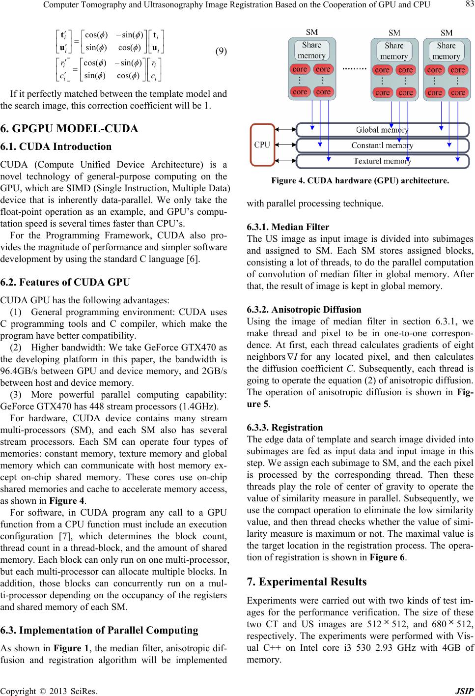 Computer Tomography and Ultrasonography Image Registration Based on the Cooperation of GPU and CPU 83 cos( )sin( ) sin( )cos( ) cos( )sin( ) sin()cos() ii ii ii ii rr cc tt uu (9) If it perfectly matched between the template model and the search image, this correction coefficient will be 1. 6. GPGPU MODEL-CUDA 6.1. CUDA Introduction CUDA (Compute Unified Device Architecture) is a novel technology of general-purpose computing on the GPU, which are SIMD (Single Instruction, Multiple Data) device that is inherently data-parallel. We only take the float-point operation as an example, and GPU’s compu- tation speed is several times faster than CPU’s. For the Programming Framework, CUDA also pro- vides the magnitude of performance and simpler software development by using the standard C language [6]. 6.2. Features of CUDA GPU CUDA GPU has the following advantages: (1) General programming environment: CUDA uses C programming tools and C compiler, which make the program have better compatibility. (2) Higher bandwidth: We take GeForce GTX470 as the developing platform in this paper, the bandwidth is 96.4GB/s between GPU and device memory, and 2GB/s between host and device memory. (3) More powerful parallel computing capability: GeForce GTX470 has 448 stream processors (1.4GHz). For hardware, CUDA device contains many stream multi-processors (SM), and each SM also has several stream processors. Each SM can operate four types of memories: constant memory, texture memory and global memory which can communicate with host memory ex- cept on-chip shared memory. These cores use on-chip shared memories and cache to accelerate memory access, as shown in Figure 4. For software, in CUDA program any call to a GPU function from a CPU function must include an execution configuration [7], which determines the block count, thread count in a thread-block, and the amount of shared memory. Each block can only run on one multi-processor, but each multi-processor can allocate multiple blocks. In addition, those blocks can concurrently run on a mul- ti-processor depending on the occupancy of the registers and shared memory of each SM. 6.3. Implementation of Parallel Computing As shown in Figure 1, the median filter, anisotropic dif- fusion and registration algorithm will be implemented Figure 4. CUDA hardware (GPU) architecture. with parallel processing technique. 6.3.1. M ed ian Filter The US image as input image is divided into subimages and assigned to SM. Each SM stores assigned blocks, consisting a lot of threads, to do the parallel computation of convolution of median filter in global memory. After that, the result of image is kept in global memory. 6.3.2. Ani sotropi c Diffusio n Using the image of median filter in section 6.3.1, we make thread and pixel to be in one-to-one correspon- dence. At first, each thread calculates gradients of eight neighbors for any located pixel, and then calculates the diffusion coefficient C. Subsequently, each thread is going to operate the equation (2) of anisotropic diffusion. The operation of anisotropic diffusion is shown in Fig- ure 5. 6.3.3. Re g i stration The edge data of template and search image divided into subimages are fed as input data and input image in this step. We assign each subimage to SM, and the each pixel is processed by the corresponding thread. Then these threads play the role of center of gravity to operate the value of similarity measure in parallel. Subsequently, we use the compact operation to eliminate the low similarity value, and then thread checks whether the value of simi- larity measure is maximum or not. The maximal value is the target location in the registration process. The opera- tion of registration is shown in Fig ure 6. 7. Experimental Results Experiments were carried out with two kinds of test im- ages for the performance verification. The size of these two CT and US images are 512512, and 680 512, respectively. The experiments were performed with Vis- ual C++ on Intel core i3 530 2.93 GHz with 4GB of memory. Copyright © 2013 SciRes. JSIP  Computer Tomography and Ultrasonography Image Registration Based on the Cooperation of GPU and CPU 84 )( IC Figure 5. Operation of anisotropic diffusion. Figure 6. Procedure of registration in CUDA. In this study, two cases, shown in Figures 7(a)-(d), are used to verify the registration performance. The re- sults of registration are shown in Figures 8(a)-(b). Here, the performance of efficiency is listed in Table 1. Ac- cording to the experimental results, the object is suc- cessful recognized in the US image, and computation cost is dramatically reduced using GPU. The computation advantage is 23.36 times. 8. Analysis of Registration Error Fiducial registration error (FRE) and target registration error (TRE) [8-10] are adapted to evaluate the accuracy of registration results. 1) FRE: distance of corresponding fiducial points after registration. 2) TRE: distance of corresponding target points after registration. Therefore, the location of fiducial points and target points are indicated by doctors. Doctors laid position of vessel, bifurcations, and the lesions to be the target point. Besides, Doctors put other locations to be fiducial points, mostly the abdominal aorta and inferior vena cava. Then the fiducial points and target points are used to calculate Root Mean Square Deviation (RMSD) by 2 ,, 1 () CT US n ii i xx RMSD n (7) where n is number of point pairs, ,,CT iUS i xis the dis- tance between the corresponding point from two different data sets. Figures 9(a)-(b), 9(c)-(d) show the location of the tar- get points and fiducial points from different cases. The fiducial points and target points are marked as triangle and circle, respectively. Then the registration error is listed in Table 2. (a) (b) (c) (d) Figure 7. Test images: (a) Case1 of CT, (b) Case1 of US, (c) Case2 of CT, (d) Case2 of US. (a) (b) Figure 8. Registration results: (a) Case1, (b) Case2. Table 1. The efficiency of the proposed method. Execute time Algorithms CPU GPU/CPU Processing in US (Median + Anisotropic) 1.33 (s) 22.09 (ms) Feature Extraction in CT 30 (ms) 30 (ms) (CPU) Feature Extraction in US 6 (ms) 6 (ms) (CPU) Registration 510.8 (ms) 18.01 (ms) Total 1.776 (s) 76.1 (ms) 9. Conclusions It is a tremendous challenge in registration of CT and US images because the CT and US images of abdominal organ images are obtained from the same patient but at different times and with different imaging modality. In this paper, through the proposed method, CT and US can Copyright © 2013 SciRes. JSIP 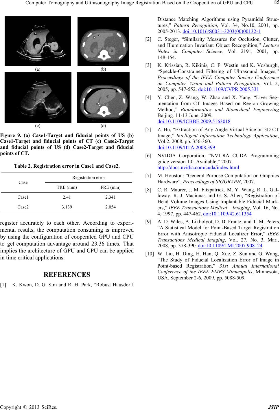 Computer Tomography and Ultrasonography Image Registration Based on the Cooperation of GPU and CPU Copyright © 2013 SciRes. JSIP 85 (a) (b) (c) (d) Figure 9. (a) Case1-Target and fiducial points of US (b) Case1-Target and fiducial points of CT (c) Case2-Target and fiducial points of US (d) Case2-Target and fiducial points of CT. Table 2. Registration error in Case1 and Case2. Registration error Case TRE (mm) FRE (mm) Case1 2.41 2.341 Case2 3.139 2.054 register accurately to each other. According to experi- mental results, the computation consuming is improved by using the configuration of cooperated GPU and CPU to get computation advantage around 23.36 times. That implies the architecture of GPU and CPU can be applied in time critical applications. REFERENCES [1] K. Kwon, D. G. Sim and R. H. Park, “Robust Hausdorff Distance Matching Algorithms using Pyramidal Struc- tures,” Pattern Recognition, Vol. 34, No.10, 2001, pp. 2005-2013. doi:10.1016/S0031-3203(00)00132-1 [2] C. Steger, “Similarity Measures for Occlusion, Clutter, and Illumination Invariant Object Recognition,” Lecture Notes in Computer Science, Vol. 2191, 2001, pp. 148-154. [3] K. Krissian, R. Kikinis, C. F. Westin and K. Vosburgh, “Speckle-Constrained Filtering of Ultrasound Images,” Proceedings of the IEEE Computer Society Conference on Computer Vision and Pattern Recognition, Vol. 2, 2005, pp. 547-552. doi:10.1109/CVPR.2005.331 [4] Y. Chen, Z. Wang, W. Zhao and X. Yang, “Liver Seg- mentation from CT Images Based on Region Growing Method,” Bioinformatics and Biomedical Engineering Beijing, 11-13 June, 2009. doi:10.1109/ICBBE.2009.5163018 [5] Z. Hu, “Extraction of Any Angle Virtual Slice on 3D CT Image,” Intelligent Information Technology Application, Vol.2, 2008, pp. 356-360. doi:10.1109/IITA.2008.399 [6] NVIDIA Corporation, “NVIDIA CUDA Programming guide version 1.0. Available,” 2007. http://docs.nvidia.com/cuda/index.html [7] M. Houston: “General-Purpose Computation on Graphics Hardware”, Proceedings of SIGGRAPH, 2007. [8] C. R. Maurer, J. M. Fitzpatrick, M. Y. Wang, R. L. Gal- loway, R. J. Maciunas and G. S. Allen, “Registration of Head Volume Images Using Implantable Fiducial Mark- ers,” IEEE Transactions Medical Imaging, Vol. 16, No. 4, 1997, pp. 447-462. doi:10.1109/42.611354 [9] A. D. Wiles, A. Likholyot, D. D. Frantz, and T. M. Peters, “A Statistical Model for Point-Based Target Registration Error with Anisotropic Fiducial Localizer Error,” IEEE Transactions Medical Imaging, Vol. 27, No. 3, Mar., 2008, pp. 378-390. doi:10.1109/TMI.2007.908124 [10] W. Liu, H. Ding, H. Han, Q. Xue, Z. Sun and G. Wang, “The Study of Fiducial Localization Error of Image in Point-based Registration,” 31st Annual International Conference of the IEEE EMBS Minneapolis, Minnesota, USA, September 2-6, 2009, pp. 5088-509.
|