Paper Menu >>
Journal Menu >>
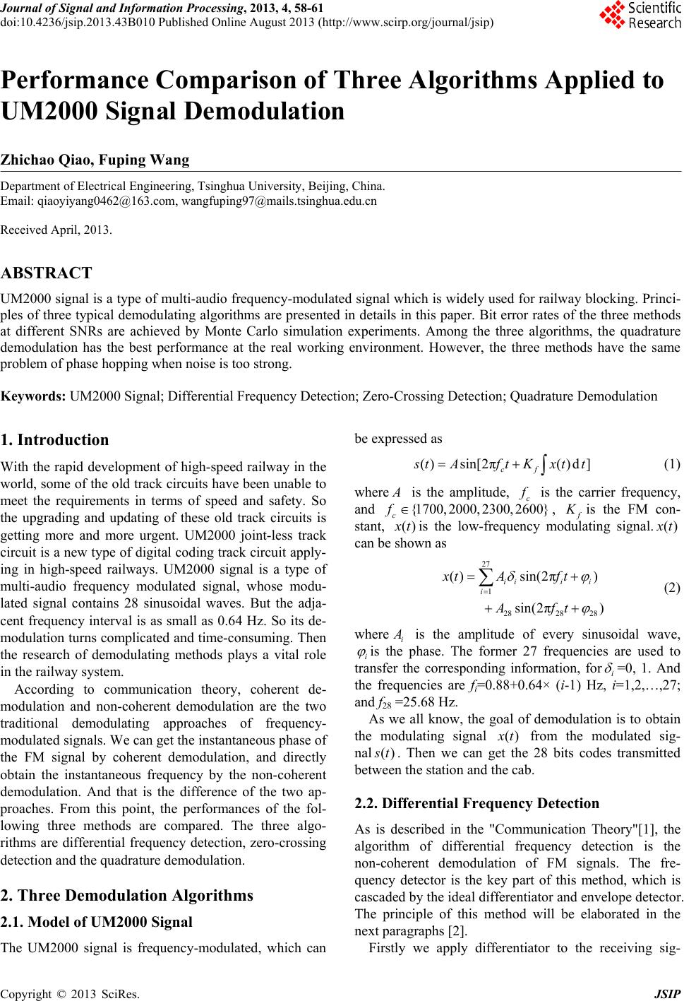 Journal of Signal and Information Processing, 2013, 4, 58-61 doi:10.4236/jsip.2013.43B010 Published Online August 2013 (http://www.scirp.org/journal/jsip) Performance Comparison of Three Algorithms Applied to UM2000 Signal Demodulation Zhichao Qiao, Fuping Wang Department of Electrical Engineering, Tsinghua University, Beijing, China. Email: qiaoyiyang0462@163.com, wangfuping97@mails.tsinghua.edu.cn Received April, 2013. ABSTRACT UM2000 signal is a type of multi-audio frequency-modulated signal which is widely used for railway blocking. Princi- ples of three typical demodulating algorithms are presented in details in this paper. Bit error rates of the three methods at different SNRs are achieved by Monte Carlo simulation experiments. Among the three algorithms, the quadrature demodulation has the best performance at the real working environment. However, the three methods have the same problem of phase hopping when noise is too strong. Keywords: UM2000 Signal; Differential Frequency Detection; Zero-Crossing Detection; Quadrature Demodulation 1. Introduction With the rapid development of high-speed railway in the world, some of the old track circuits have been unable to meet the requirements in terms of speed and safety. So the upgrading and updating of these old track circuits is getting more and more urgent. UM2000 joint-less track circuit is a new type of digital coding track circuit apply- ing in high-speed railways. UM2000 signal is a type of multi-audio frequency modulated signal, whose modu- lated signal contains 28 sinusoidal waves. But the adja- cent frequency interval is as small as 0.64 Hz. So its de- modulation turns complicated and time-consuming. Then the research of demodulating methods plays a vital role in the railway system. According to communication theory, coherent de- modulation and non-coherent demodulation are the two traditional demodulating approaches of frequency- modulated signals. We can get the instantaneous phase of the FM signal by coherent demodulation, and directly obtain the instantaneous frequency by the non-coherent demodulation. And that is the difference of the two ap- proaches. From this point, the performances of the fol- lowing three methods are compared. The three algo- rithms are differential frequency detection, zero-crossing detection and the quadrature demodulation. 2. Three Demodulation Algorithms 2.1. Model of UM2000 Signal The UM2000 signal is frequency-modulated, which can be expressed as () sin[2π()d ] cf s tA ftKxtt (1) where A is the amplitude, c f is the carrier frequency, and {1700, 2000, 2300,0}260 c f , f K is the FM con- stant, () x tis the low-frequency modulating signal.() x t can be shown as 27 1 2828 28 () sin(2π) sin(2π) iii i i xt Aft Aft (2) where i A is the amplitude of every sinusoidal wave, i is the phase. The former 27 frequencies are used to transfer the corresponding information, fori =0, 1. And the frequencies are fi=0.88+0.64× (i-1) Hz, i=1,2,…,27; and f28 =25.68 Hz. As we all know, the goal of demodulation is to obtain the modulating signal () x t from the modulated sig- nal () s t. Then we can get the 28 bits codes transmitted between the station and the cab. 2.2. Differential Frequency Detection As is described in the "Communication Theory"[1], the algorithm of differential frequency detection is the non-coherent demodulation of FM signals. The fre- quency detector is the key part of this method, which is cascaded by the ideal differentiator and envelope detector. The principle of this method will be elaborated in the next paragraphs [2]. Firstly we apply differentiator to the receiving sig- Copyright © 2013 SciRes. JSIP  Performance Comparison of Three Algorithms Applied to UM2000 Signal Demodulation 59 nal () s t. We get its differential,() d s t, which is noted as () [2π()] cos[2π()d] dcf cf stA fKxt f tK xtt (3) After the differential, the FM signal turns to be the signal modulated by amplitude and frequency. From Equation (3), we can easily see that the envelope of () d s t contains the information of() x t. Then we can get its envelope by Hilbert Transform, that is ˆ() [2π()] sin[2π()d] dcf cf stA fKxt f tK xtt (4) Getting the square root of () d s tand ˆ() d s t as 22 [2π()] ˆ() () d cf d EvAfKx t s tst (5) By removing the DC component by a filter, we get the modulating signal() x t. So far, the demodulation of the UM2000 signal has been achieved according to the algo- rithm of differential frequency detection. 2.3. Zero-Crossing Detection The algorithm of zero-crossing detection [3], also known as the counting method, is the easiest approach to meas- ure the instantaneous frequency. The principle is effec- tive for the UM2000 signal demodulation because the zero-crossing sequence directly reflects the signal’s pe- riod. For the UM2000 signal, its instantaneous frequency can be noted as () 2π f c K I Ff xt (6) The relationship of modulating signal () x tand the in- stantaneous frequency I Fis clearly shown in Equation (6). Then we can get the instantaneous frequency by de- tecting the zero-crossing sequence. The specific steps are clearly elaborated below. Firstly, get the zero-crossing sequence. Then the intervals sequence can be obtained as ()zero i () [(1)()]/ s intervalizero izero if (7) where s f is the sampling frequency. Because the inter- vals represent the signal’s half-cycle, we can get 1/[2( )] I Finterval i (8) According to Equation (6), we get 2π () () c f xtIFf K (9) At last, filtering and interpolation are necessary to ob- tain the real modulating signal() x t. So far, the process of demodulation by the method of zero-cross detection has been completed. 2.4. Quadrature Demodulation A common ground of the former two methods shown in section 2.2 and 2.3 is to obtain the instantaneous fre- quency directly. Whereas the quadrature demodulation [4], its core step is to get the signal’s phase, ()d f K xt t . The principle will be elaborated later. We make the carrier signal and () s t to be the inputs of the multiplier. We can get ()() cos(2π) sin[4π()d ] 2 sin[()d] 2 Ic cf f st stft A f tK xtt AKxtt (10) ()() sin(2π) cos[4π()d ] 2 cos[()d] 2 Qc cf f st stft A f tK xtt AKxtt (11) Then a low pass filter is designed to remove the high- frequency components. So we have the in-phase compo- nent and the quadrature-phase component of the phase signal as follows. ()sin[()d ] 2f A I tKxtt (12) ()cos[()d ] 2f A QtKxt t (13) Then we use anti-trigonometric functions to obtain the phase signal()d f K xt t . Thus, the modulating signal () x t can be derived as d ()[ ()/] df x tt t K s (14) Therefore, the demodulating has been achieved by quadrature demodulation. 3. Simulations In order to compare demodulation performance of the three algorithms objectively[5], we chose the same envi- ronment and parameters when simulated in MATLAB. The sampling frequency is set as Hz. The sampling time is 16384 s f 3.125 d T . The carrier frequency is 2000 c f Hz. The message matrix of UM2000 signal is . The sig- nal-to-noise ratio is set as SNR=20dB. Their simulation results are shown in the next parts. =[0011110001011110011110 1110]Delta Copyright © 2013 SciRes. JSIP 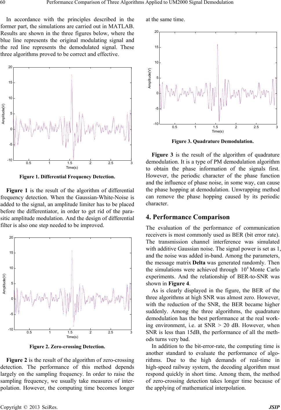 Performance Comparison of Three Algorithms Applied to UM2000 Signal Demodulation 60 In accordance with the principles described in the former part, the simulations are carried out in MATLAB. Results are shown in the three figures below, where the blue line represents the original modulating signal and the red line represents the demodulated signal. These three algorithms proved to be correct and effective. 0.5 11.5 22.5 3 -10 -5 0 5 10 15 20 Time(s) Amplitude(V) Figure 1. Differential Frequency Detec tion. Figure 1 is the result of the algorithm of differential frequency detection. When the Gaussian-White-Noise is added to the signal, an amplitude limiter has to be placed before the differentiator, in order to get rid of the para- sitic amplitude modulation. And the design of differential filter is also one step needed to be improved. 0.5 11.522.5 3 -10 -5 0 5 10 15 20 Time(s) A mpl i t ude(V ) Figure 2. Zero-crossing Detection. Figure 2 is the result of the algorithm of zero-crossing detection. The performance of this method depends largely on the sampling frequency. In order to raise the sampling frequency, we usually take measures of inter- polation. However, the computing time becomes longer at the same time. 0.5 11.5 22.5 3 -10 -5 0 5 10 15 20 Time(s) A m pl itude(V ) Figure 3. Quadrature Demodulation. Figure 3 is the result of the algorithm of quadrature demodulation. It is a type of PM demodulation algorithm to obtain the phase information of the signals first. However, the periodic character of the phase function and the influence of phase noise, in some way, can cause the phase hopping at demodulation. Unwrapping method can remove the phase hopping caused by its periodic character. 4. Performance Comparison The evaluation of the performance of communication receivers is most commonly used as BER (bit error rate). The transmission channel interference was simulated with additive Gaussian noise. The signal power is set as 1, and the noise was added in-band. Among the parameters, the message matrixwas generated randomly. Then the simulations were achieved through Monte Carlo experiments. And the relationship of BER-to-SNR was shown in Figure 4. Delta 4 10 As is clearly displayed in the figure, the BER of the three algorithms at high SNR was almost zero. However, with the reduction of the SNR, the BER became higher suddenly. Among the three algorithms, the quadrature demodulation has the best performance at the real work- ing environment, i.e. at SNR > 20 dB. However, when SNR is less than 15dB, the performance of all the meth- ods turns very bad. In addition to the bit-error-rate, the computing time is another standard to evaluate the performance of algo- rithms. Due to the high demands of real-time in high-speed railway system, the decoding algorithm must respond quickly in short time. Among them, the method of zero-crossing detection takes longer time because of the applying of mathematical interpolation. Copyright © 2013 SciRes. JSIP 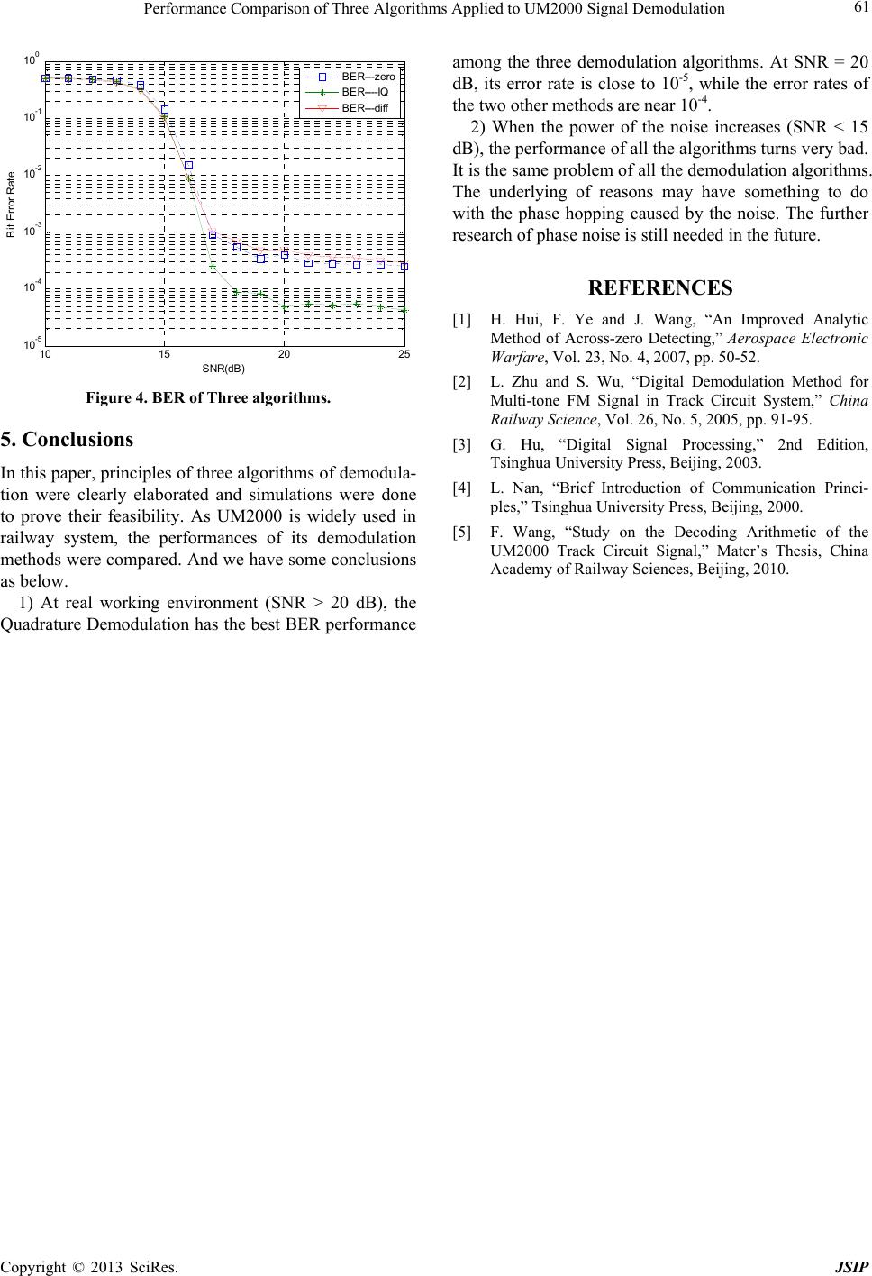 Performance Comparison of Three Algorithms Applied to UM2000 Signal Demodulation Copyright © 2013 SciRes. JSIP 61 10 152025 10 -5 10 -4 10 -3 10 -2 10 -1 10 0 S NR(d B ) B i t Error Rate BER---zero BER----IQ BER---diff Figure 4. BER of Three algorithms. 5. Conclusions In this paper, principles of three algorithms of demodula- tion were clearly elaborated and simulations were done to prove their feasibility. As UM2000 is widely used in railway system, the performances of its demodulation methods were compared. And we have some conclusions as below. 1) At real working environment (SNR > 20 dB), the Quadrature Demodulation has the best BER performance among the three demodulation algorithms. At SNR = 20 dB, its error rate is close to 10-5, while the error rates of the two other methods are near 10-4. 2) When the power of the noise increases (SNR < 15 dB), the performance of all the algorithms turns very bad. It is the same problem of all the demodulation algorithms. The underlying of reasons may have something to do with the phase hopping caused by the noise. The further research of phase noise is still needed in the future. REFERENCES [1] H. Hui, F. Ye and J. Wang, “An Improved Analytic Method of Across-zero Detecting,” Aerospace Electronic Warfare, Vol. 23, No. 4, 2007, pp. 50-52. [2] L. Zhu and S. Wu, “Digital Demodulation Method for Multi-tone FM Signal in Track Circuit System,” China Railway Science, Vol. 26, No. 5, 2005, pp. 91-95. [3] G. Hu, “Digital Signal Processing,” 2nd Edition, Tsinghua University Press, Beijing, 2003. [4] L. Nan, “Brief Introduction of Communication Princi- ples,” Tsinghua University Press, Beijing, 2000. [5] F. Wang, “Study on the Decoding Arithmetic of the UM2000 Track Circuit Signal,” Mater’s Thesis, China Academy of Railway Sciences, Beijing, 2010. |