Paper Menu >>
Journal Menu >>
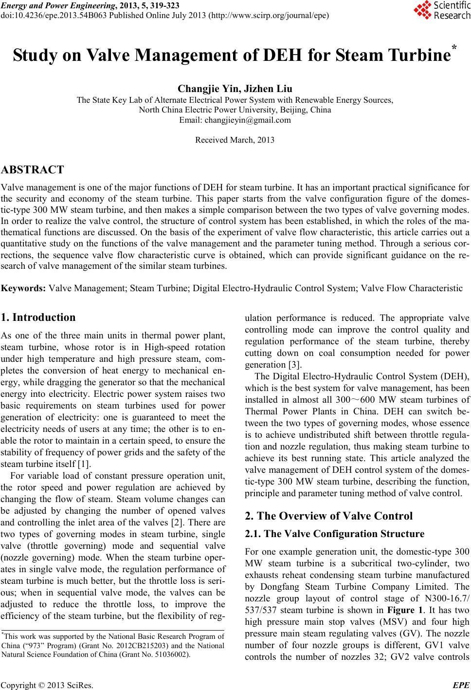 Energy and Power E ngineering, 2013, 5, 319-323 doi:10.4236/epe.2013.54B063 Published Online July 2013 (http://www.scirp .o rg/journal/epe) Copyright © 2013 SciRes. EPE Study on Valve Management of DEH for Steam Turbine* Changjie Yin, Jizhen Liu The State Key Lab of Alternate Electr ical Power System with Renewable Energy Sources, North China Electric Power University , Beijing, China Email: changjieyin@gmail.co m Received March, 2013 ABSTRACT Valve management is one of the major functions of DEH for steam turbine. It has an important practical significance for the security and economy of the steam turbine. This paper starts from the valve configuration figure of the domes- tic-type 300 MW steam turb in e , a nd then makes a simple comparison between the two types of valve gove r ning mo des. In order to realize the valve co ntrol, the structure of control system has been established, in which the roles of the ma- thematical functions are discussed. On the basis of the experiment of valve flow characteristic, thi s article carries out a quantitative study on the functions of the valve management and the parameter tuning method. Through a serious cor- rections, the sequence valve flow characteristic curve is obtained, which can provide significant guidance on the re- search of valve manageme nt o f the similar steam turbines. Keywords: Valve Mana gement; Steam T urbine ; Digital Ele c tr o-Hydraulic Control System; Valve Flow Characteristic 1. Introd uction As one of the three main units in thermal power plant, steam turbine, whose rotor is in High-speed rotation under high temperature and high pressure steam, com- pletes the conversion of heat energy to mechanical en- erg y, wh il e d r a ggi n g t he ge ne r at or so that the mechanical energy into electricity. Electric power system raises two basic requirements on steam turbines used for power generation of electricity: one is guaranteed to meet the electricity needs of users at any time; the other is to en- able the roto r to maintain in a certain speed, to e ns ur e t he stab ili t y o f freq uenc y o f power gri ds and the sa fe t y of t he steam turbine it self [1]. For variable load of constant pressure operation unit, the rotor speed and power regulation are achieved by changing the flow of steam. Steam volume changes can be adjusted by changing the number of opened valves and controlling the inle t area of the valve s [2]. There are two types of governing modes in steam turbine, single valve (throttle governing) mode and sequential valve (nozzle governing) mode. When the steam turbine oper- ates in single valve mode, the regulation performance of steam turbine is much better, but the throttle loss is seri- ous; when in sequential valve mode, the valves can be adjusted to reduce the throttle loss, to improve the efficiency of the steam turbine, but the flexibility of reg- ulation performance is reduced. The appropriate valve controlling mode can improve the control quality and regulation performance of the steam turbine, thereby cutting down on coal consumption needed for power gener ation [3]. The Digital Electro-Hydraulic Control System (DEH), whic h is t he be st s yste m for valve mana ge ment, has b ee n installed in almost all 300~600 MW steam turbines of Thermal Power Plants in China. DEH can switch be- tween the two types of governing modes, whose essence is to achieve undis tr ib uted shift between throttle regula- tion and nozzle regulation, thus making steam turbine to achieve i ts best running sta te. This article analyzed the valve mana gement of DEH co ntrol system of the domes- tic-type 300 MW steam turbine, describing the function, principle and parameter tuning method of valve control. 2. The Overview of Valve Control 2.1. The Valve Configuration Structure For one example generation unit, the domestic-type 300 MW steam turbine is a subcritical two-cylinder, two exhausts reheat condensing steam turbine manufactured by Dongfang Steam Turbine Company Limited. The nozzle group layout of control stage of N300-16.7/ 537/537 steam turbine is shown in Figure 1. It has two high pressure main stop valves (MSV) and four high pressure main steam regulating valves (GV). The nozzle number of four nozzle groups is different, GV1 valve controls the number of nozzles 32; GV2 valve controls *This work was supported by the National Basic Research Pro gram of China (“973” Program) (Grant No. 2012CB215203) and the Na tional Natural Science Foundati on of China (Grant No. 51036002 ).  C. J. YIN, J. Z. LIU Copyright © 2013 SciRes. EPE 320 the number of nozzles 32; GV3 valve controls the num- ber of nozzles 30; GV4 valve controls the number of nozzles 27. Whe n the ste am t urb ine i s in a normal opera- tion, the main st op val ves are fully opened and the steam flow is controlled by the four contro l valves. 2.2. Comparison of the Single Valve Mode and Sequence Va lve Mode For the constant pressure operation of power generation units, steam turbine regulation is mainly to regulate the speed of rotor and the power of generator, which are achieved by regulating the steam flow. The amount of inlet flow is altered by changing the number of opened valves and va l ve op e nin g, namel y c ha ngi n g the to ta l inl e t area of steam turbine. Therefore, depending on how to change the inlet area of valves, we can divide the control mode into two types: single valve mode and sequential valve mode, which have their own advantages and dis- advantages. Single valve control means that all the control valves accept a valve control signal to make the valves turn up or down at the same time, which is characterized by the throttle adjusting and full arc admission. The cylinder rotor heat expansion is uniform and the metal tempera- ture of different steam turbine parts is in a stable condi- tion, making the unit withstand greater load change rate. But because all of the adjustment valves are not in the fully opened state, the valves have a great throttle loss, reducing t he thermal efficiency of t he unit. Sequence valve control means that the control valve turns on o r off ind ividual ly along wit h the rotor speed or turbine load changing, which is characterized by the nozzle adj usting and partial arc admissio n. That is to say, at any time only one steam valve is in a non-fully open state while the o t her val ve s a r e in full y op e n state o r full y closed state. This control mode reduces the throttling losse s and ther eb y i mproves the the rmal e f ficie nc y of t he stea m turb ine. B ut because the position of the stea m inlet is asymmetric, the cylinder rotor heat expansion is un- even and the metal temperature difference of different steam turbine parts is rather large, and the unit ca nnot withstand greater load change rate. Figure 2 is the 300 MW unit’s thermal efficiency curve of si ngle valve control and sequence valve control. When the load percentage is 60%, sequence valve mode can improve thermal efficiency by about 3%. 3. The Principle of the Valve Control The function of valve control is to transfer the required flow into the degree of valve opening. In order to realize the function, there are several mathematical functions used to correct the flow and distributing it among the four valves. For a valve, the valve control structure is shown in Figure 3, in which the roles of functions are explained as follows. 3.1. Flow Pressure Correc tion Fun ct ion f(x1) and f(x4) Function 1 ()fx and 4 () fx are correction functions between the unit’s theoretical demand flow and the actual demand flow. Under low load condition, actual demand flo w is equal to the theoretical demand flo w. But as the load increases, the pressure of steam turbine governing stage rises and its actual amount of steam decreases although under the same valve opening. That is to say actual demand flow is higher than the theoretical demand flow. Therefore, the functions are used for amending the flow directive at different load levels, to ensure the consistency of the theoretical flow and the actual flow. Main stream MSV2 MSV1 Bottom part Upper part GV1 GV4 GV3 GV2 Rotating direction 32 30 32 27 Figure 1 . The nozzle gro up s s t ructure chart of control st age. 55 60 65 70 7580 85 9095100 Load perc ent age (%) Thermal eff i ci ency (% ) Sequence valve mode Si ngl e valve mode 3% Figure 2. Ther mal efficiency comparison chart. Sequence valve mode 1 ()fx KB+ 2 ()fx 3 ()fx 4 ()fx Single valve mode T Y N Valve opening FDEM Figure 3. Func tional s tructure of valve c ontrol system. 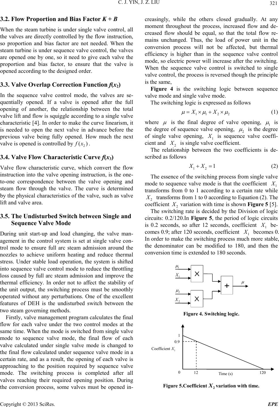 C. J. YIN, J. Z. LIU Copyright © 2013 SciRes. EPE 321 3.2. Flow Proportion and Bias Factor K + B When the steam turbine is under single valve control, all the valves are directly controlled by the flo w instr uction, so proportion and bias factor are not needed. When the steam turbine is under sequen ce valve control, the valves are opened one by one, so it need to give each valve the proportion and bias factor, to ensure that the valve is opened according to the designed order. 3.3. Valve Overlap Correction Function f(x2) In the sequence valve control mode, the valves are se- quentially opened. If a valve is opened after the full opening of another, the relationship between the total valve lift and flo w is squiggle according to a single val ve characteristic [4]. In order to ma ke the c urve line ari sm, it is needed to open the next valve in advance before the previous valve being fully opened. How much the next valve is opened is controlled by2 () fx . 3.4. Valve Flow Characteristic Curve f(x3) Valve flow characteristic curve, which convert the flow instruction into the valve opening instr uction, is the one- to-one correspondence between the valve opening and steam flow through the valve. The curve is determined by the physical characteristics of the valve, such as valv e lift and valve area. 3.5. The Undisturbed Switch between Single and Sequence Va lve Mode During unit start-up and load changing, the valve man- agement in the control system is set at single valve con- trol mode to ensure full arc steam admission around the nozzles to achieve uniform heating and reduce thermal stress. Under stable load operation, the system is shifted into sequence valve contro l mode to reduce the thro ttling loss caused by full arc steam admission and improve the thermal efficiency. In order not to affect the stability of the unit output, the switching process must be smoothly operated without any perturbations. One of the excellent features of DEH is the undisturbed switch between the two steam governing methods. First l y, va l ve ma na ge me n t p r ogram calc ul ates the fi nal flow for each valve under the two control modes at the same ti me. Whe n the mod e is switc hed fro m sin gle va lve mode to sequence valve mode, the final flow of each valve calculated under single valve mode is changed to the final flow calculated under sequence valve mode in a certain rate, and as a result, the opening of each valve is approaching to the position required by sequence valve mode. The switching process is completed after all valves reaching their required opening position. During the conversion process, some valves must be opened in- creasingly, while the others closed gradually. At any moment throughout the process, increased flow and de- creased flow should be equal, so that the total flow re- mains unchanged. Thus, the load of power unit in the conversion process will not be affected, but thermal efficiency is higher than in the sequence valve control mode, so electric power will increase after the switching. When the sequence valve control is switched to single valve control, the process is reversed though the princip le is the same, Figure 4 is the switching logic between sequence valve mode and single valve mode. The switching logic is expressed as follows 112 2 XX µµ µ = ×+× (1) whe r e µ is the final degree of valve opening, 1 µ is the degree of sequence valve opening, 2 µ is the degree of single valve opening, 1 X is sequence valve coeffi- cient and 2 X is single valve coefficient. The relationship between the two coefficients is de- scribed as follows 12 1XX+= (2) The essence of the switching process from single valve mode to sequence valve mode is that the coefficient 1 X transforms from 0 to 1 according to a certain rate while 2 X transforms from 1 to 0 according to Equation (2). The coefficient 2 X variation wit h time is shown Figure 5 [5]. The switching rate is decided by the Division of logic circuits: 0.2/120.In Figure 5, the period of logic circuits is 0.2 seconds, so after 12 seconds, coefficient 1 X be- comes 0.9; after 120 seconds, coefficient 1 X becomes 0. In order to make the switching process much more stable, the denominator can be modified to 180, and then the conversion time is extended to 180 seconds. 1 X 2 X 1 µ 2 µ µ Figure 4 . Switching log ic. Time (s) 0.9 1 0 12 120 Coefficient 1 X Figure 5 .Coefficient2 X variation with time. 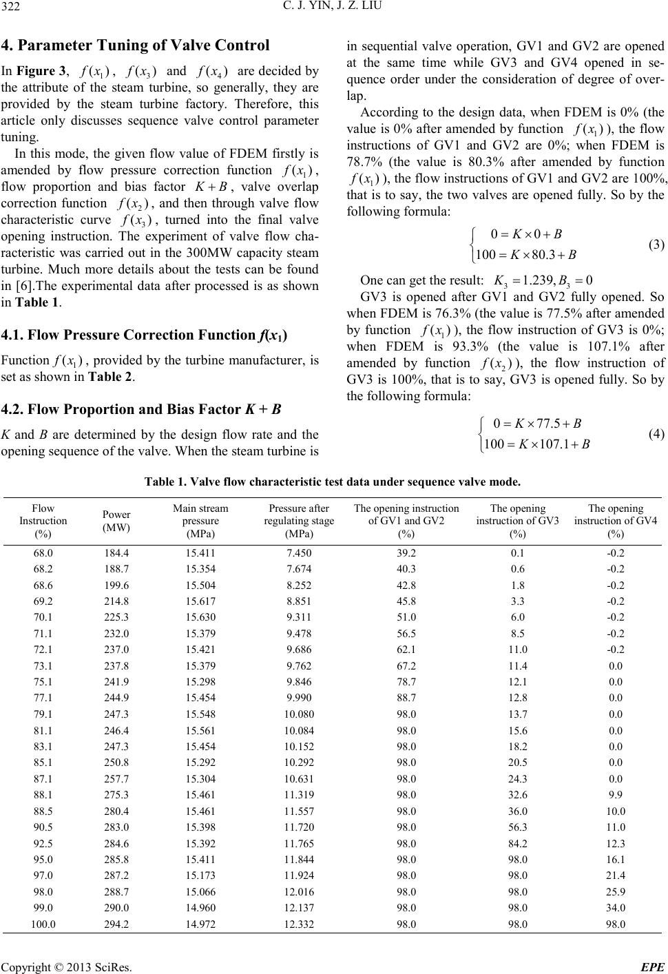 C. J. YIN, J. Z. LIU Copyright © 2013 SciRes. EPE 322 4. Parameter Tuning of Valve Control In Figur e 3, 1 ()fx , 3 () fx and 4 () fx are decided by the attribute of the steam turbine, so generally, they are provided by the steam turbine factory. Therefore, this article only discusses sequence valve control parameter tuning. In this mode, the given flow value of FDEM firstly is amended by flow pressure correction function 1 ()fx , flow proportion and bias factor KB+ , valve overlap correction function 2 () fx , and then through valve flow characteristic curve 3 () fx , turned into the final valve opening instruction. The experiment of valve flow cha- racteristic was carried out in the 300MW capacity steam turbine. Much more details about the tests can be found in [6].The experimental data after processed is as shown in Table 1. 4.1. Flow Pressu re Cor rec tion Fun ct ion f(x1) Function 1 ()fx , provided by the turbine manufacturer, is set as shown in Table 2. 4.2. Flow Proportion and Bias Factor K + B K and B are determined by the design flow rate and the opening sequence of the valve. When the ste a m t urb ine is in sequential valve operation, GV1 and GV2 are opened at the same time while GV3 and GV4 opened in se- quence order under the consideration of degree of over- lap. According to the design data, when FDEM is 0% (the value is 0% af ter a mend ed by f unctio n 1 () fx ), the flow instructions of GV1 and GV2 are 0%; when FDEM is 78.7% (the value is 80.3% after amended by function 1 () fx ), the flow instructions of GV1 and GV2 are 100%, that is to sa y, the two valves are opened fully. So by the following for mula: 00 100 80.3 KB KB = ×+ =×+ (3) One can get the result: 33 1.239, 0KB= = GV3 is opened after GV1 and GV2 fully opened. So whe n FDEM is 7 6. 3% ( the va lue is 77.5% after amended by function 1 ()fx ), the flow instruction of GV3 is 0%; when FDEM is 93.3% (the value is 107.1% after amended by function 2 () fx ), the flow instruction of GV3 is 100%, that is to say, GV3 is opened fully. So by the followin g formula: 0 77.5 100 107.1 KB KB =×+ =×+ (4) Table 1. Valve flow characteristic test data u nder sequence valve mode. Flow Instructio n (%) Power (M W) Main stream pressure (MPa) Press ure af ter regulating stage (MPa) The opening instruction of GV1 and GV2 (%) The opening instruction of GV3 (%) The opening instruction of GV4 (%) 68.0 184.4 15. 411 7.450 39.2 0.1 -0.2 68.2 188.7 15. 354 7.674 40.3 0.6 -0.2 68.6 199.6 15. 504 8.252 42.8 1.8 -0.2 69.2 214.8 15. 617 8.851 45.8 3.3 -0.2 70.1 225.3 15. 630 9.311 51.0 6.0 -0.2 71.1 232.0 15. 379 9.478 56.5 8.5 -0.2 72.1 237.0 15. 421 9.686 62.1 11.0 -0.2 73.1 237.8 15. 379 9.762 67.2 11.4 0.0 75.1 241.9 15. 298 9.846 78.7 12.1 0.0 77.1 244.9 15. 454 9.990 88.7 12.8 0.0 79.1 247.3 15.548 10.080 98.0 13.7 0 .0 81.1 246.4 15. 561 10.084 98.0 15.6 0.0 83.1 247.3 15. 454 10.152 98.0 18.2 0.0 85.1 250.8 15. 292 10.292 98.0 20.5 0.0 87.1 257.7 15. 304 10.631 98.0 24.3 0.0 88.1 275.3 15. 461 11.319 98.0 32.6 9.9 88.5 280.4 15. 461 11.557 98.0 36.0 10.0 90.5 283.0 15. 398 11.720 98.0 56.3 11.0 92.5 284.6 15. 392 11.765 98.0 84.2 12.3 95.0 285.8 15. 411 11.844 98.0 98.0 16.1 97.0 287.2 15. 173 11.924 98.0 98.0 21.4 98.0 288.7 15. 066 12.016 98.0 98.0 25.9 99.0 290.0 14. 960 12.137 98.0 98.0 34.0 100.0 294.2 14.972 12.332 98.0 98.0 98.0 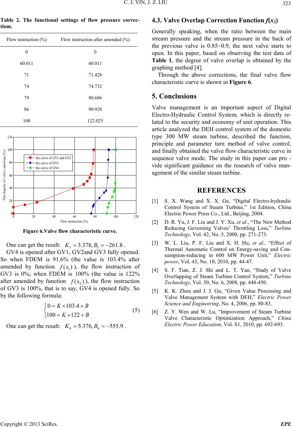 C. J. YIN, J. Z. LIU Copyright © 2013 SciRes. EPE 323 Table 2. The functional settings of flow pressure correc- tiom. Flow instruction (%) Flow instruction after amended (%) 0 0 60.011 60.011 71 71.428 74 74.732 79 80.686 86 90.928 100 122.025 020 40 60 80 100 120 0 20 40 60 80 100 120 Flow instr uc tion (%) The degree of valve opening (%) the c urve of GV1 and GV2 the c urve of GV3 the c urve of GV4 Figure 6 .Valve flow charact eristic cur ve. One can get the result: 33 3.378, 261.8KB== − . GV4 is opened after GV1, GV2and GV3 fully opened. So when FDEM is 91.6% (the value is 103.4% after amended by function 1 ()fx ), the flow instruction of GV3 is 0%; when FDEM is 100% (the value is 122% after amended by function 2 ()fx ), the flow instruction of GV3 is 100%, that is to say, GV4 is opened fully. So by the following formula: 0 103.4 100 122 KB KB =×+ =×+ (5) One can get the result: 44 5.376, 555.9KB== − . 4.3. Valve Overlap Correction Function f(x2) Generally speaking, when the ratio between the main stream pressure and the stream pressure in the back of the previous valve is 0.85~0.9, the next valve starts to open. In this paper, based on observing the test data of Table 1, the degree of valve overlap is obtained by the graphing method [4]. Through the above corrections, the final valve flow characteristic curve is shown in Figure 6. 5. Conclusions Valve management is an important aspect of Digital Electro-Hydraulic Control System, which is directly re- lated to the security and economy of unit operation. This article analyzed the DEH control system of the do mestic type 300 MW steam turbine, described the function, principle and parameter turn method of valve control, and finall y obtained the valve flow characteristic curve in sequence valve mode. The study in this paper can pro - vide significant guidance on the research of valve man- age ment of the similar steam turbine. REFERENCES [1] S. X. Wang and X. X. Ge, “Digital Electro -hydraulic Control System of Steam Turbine,” 1st Edition, China Electric Power Press Co., Ltd., Beijing, 2004. [2] D. R. Yu, J. F. Liu and J. Y. Xu, et al., “The New Method Reducing Governing Valves’ Throttling Loss,” Turbine Technology, Vol. 42, No. 5, 2000, pp. 271-273. [3] W. L. Liu, P. F. Liu and X. H. Hu, et al., “Effect of Thermal Automatic Control on Energy-saving and Con- sumption-reducing in 600 MW Power Unit,” Electric power, Vol. 43, No. 10 , 2 01 0, pp. 44-47. [4] S. F. Tian, Z. J. Shi and L. T. Yan, “Study of Valve Overlapping of Steam Turbine Control System,” Turbine Technology, Vol. 50, No. 6, 2008, pp. 448-450. [5] K. K. Zhou and J. J. Gu, “Given Value Processing and Valve Management System with DEH,” Electric Power Science and Engineering, No. 4, 2006, pp. 80-83. [6] Z. Y. Wen and W. Lu, “Improvement of Steam Turbine Valve Characteristic Optimization Approach,” China Electric Power Education, Vol. S1, 2010, pp. 692-693. |