Y. ZHAO ET AL.
262
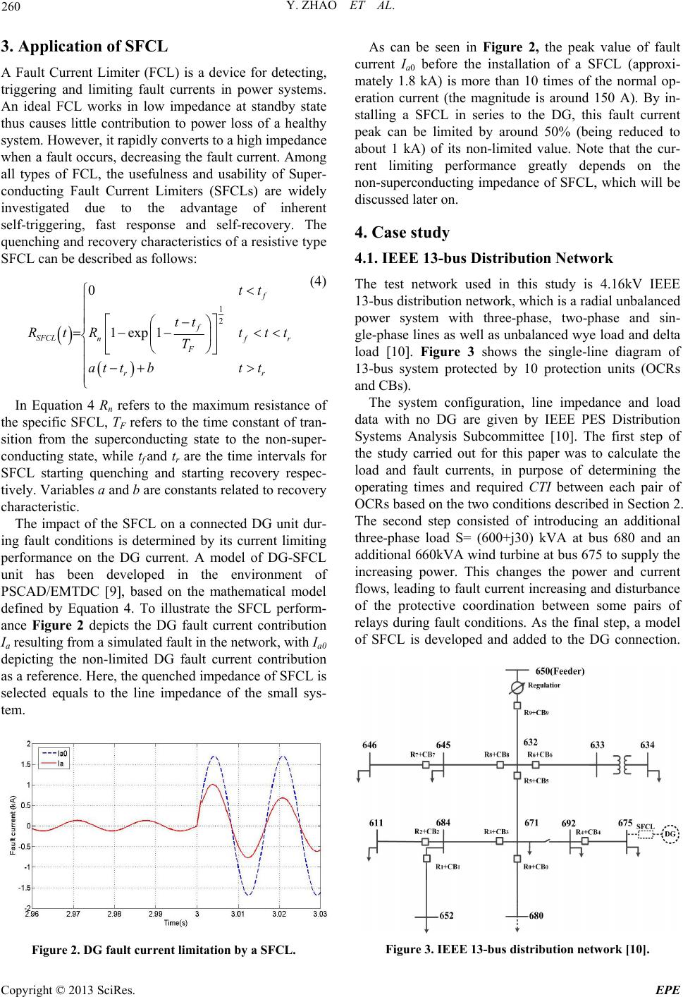
bus 680, R0 works as the primary relay while R5 is the
back-up relay. The coordinated conditions of primary
and back-up relays are similar for faults located at other
buses in Tables 2 and 3.
It can be seen from Tables 2 and 3 that most of CTIs,
especially for faults close to the DG are affected by the
presence of DG. The values of CTIs may increase or de-
crease with respects to their locations and distance to the
DG unit as analyzed in Section 2. In this case, the in-
creasing CTIs are still in the range and need no adjust-
ment. However, among those decreased CTIs, the
CTI_1,3 (phase A) and CTI_2,3 (phase C) drop below
0.2s, which is out of the acceptable range. Therefore, the
coordination of these two pairs of OCRs needs to be re-
stored, e.g. by means of a SFCL.
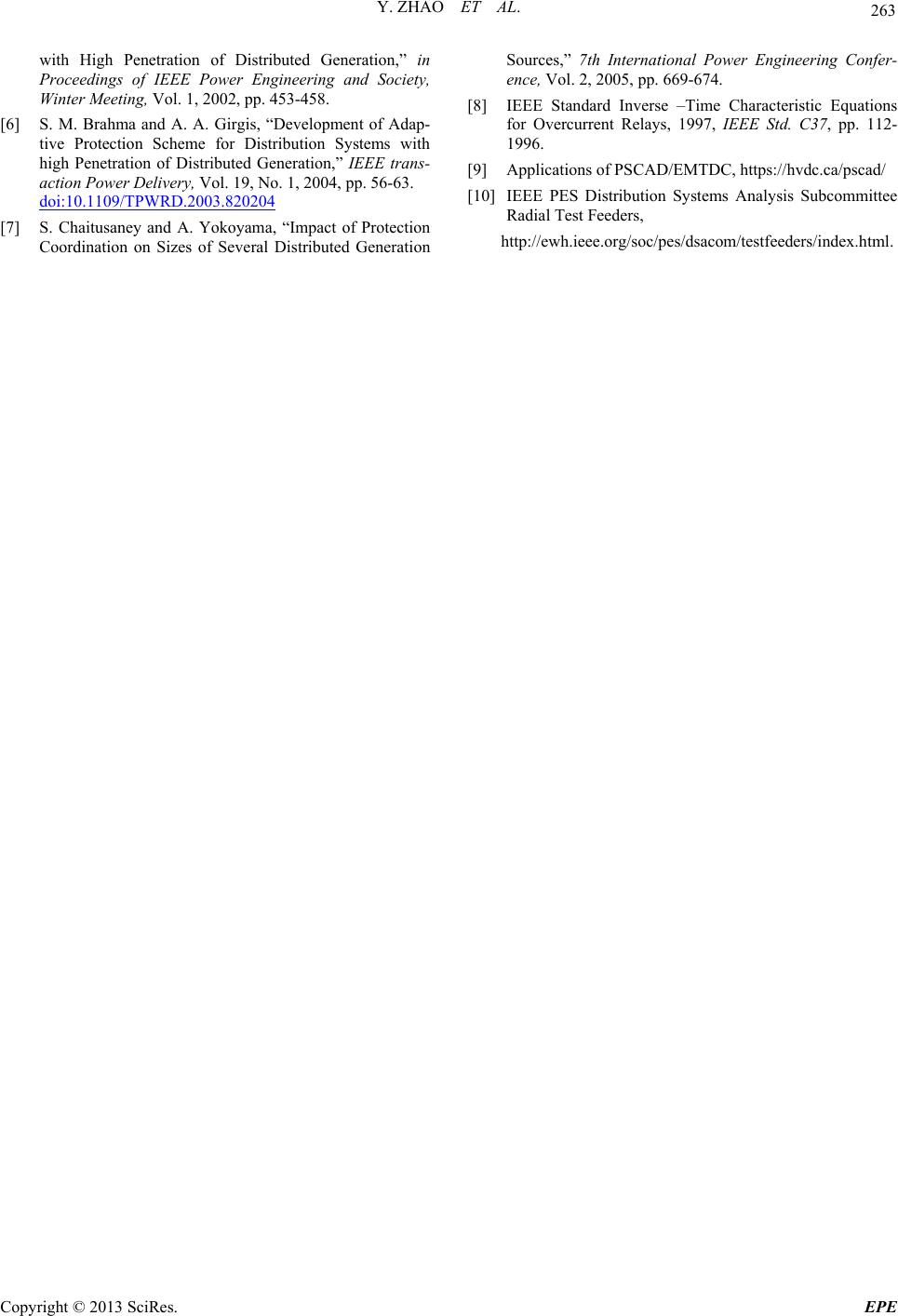
Figure 5 shows the improvement of these two CTIs
when a SFCL is installed, where . Under
the presence of a SFCL, both of these two CTIs have
been improved to over 0.2s, which satisfy the range re-
quirement mentioned in Section 2. In addition, the con-
tribution of SFCL to the improvement of the CTIs is
more significant when the OCR pairs are located closer
to the DG-SFCL unit. For instance, compared with
CTI_1,3 (increasing by 0.034s), CTI_7,8 (phase C) just
increases from 0.200s to 0.209s under the same situation.
2pu
SFCL
R
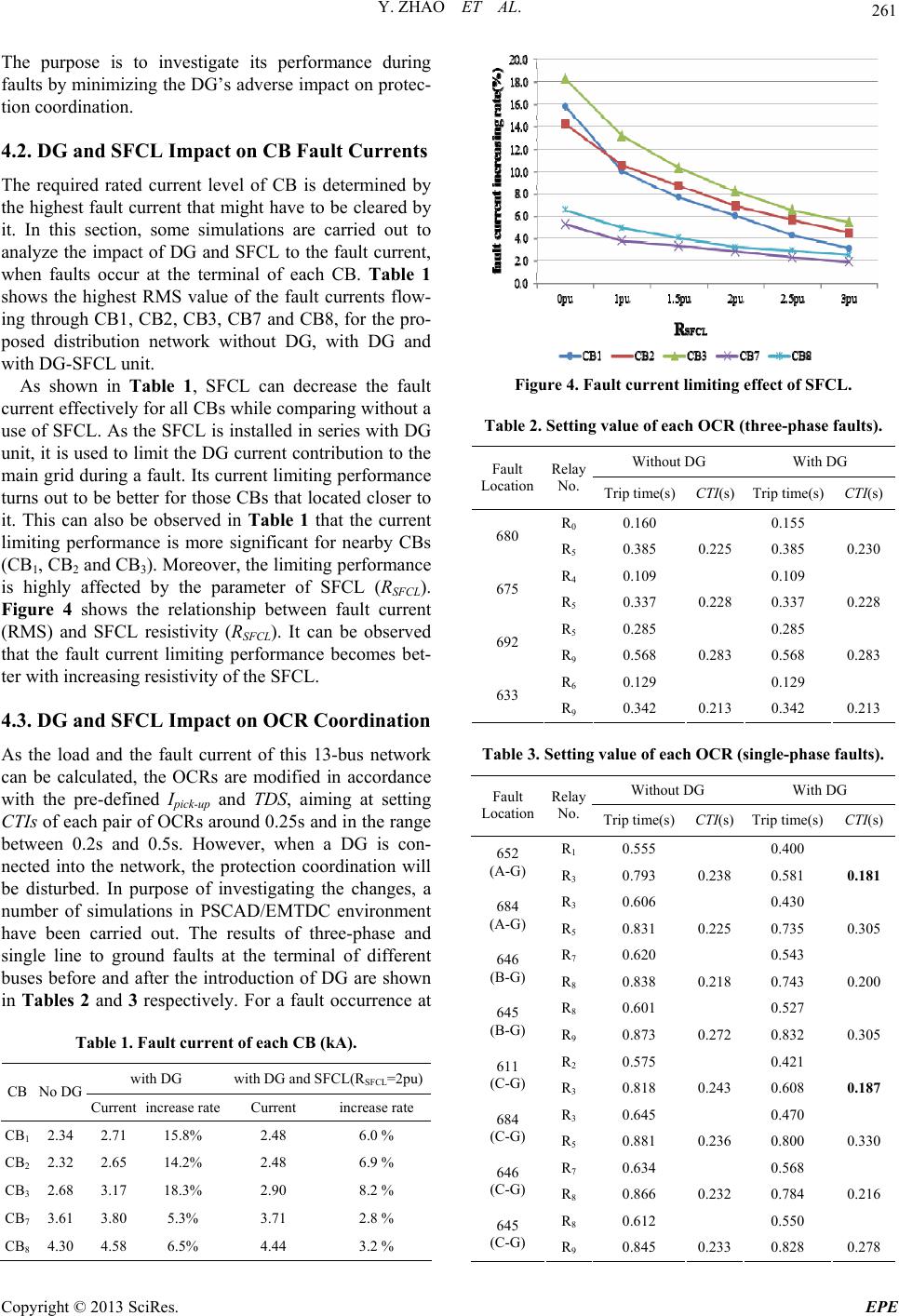
To further investigate the relationship between differ-
ent values of SFCL parameter SFCL and CTIs, SFCL is
set to 1pu, 1.5pu, 2pu, 2.5pu, and 3pu. The simulation
results are shown in Table 4. It is found that the larger
the SFCL resistivity, the closer is the CTIs to their pre-
vious determined setting values (see Table 3).
R R
Figure 5. Comparison of CTIs.
Table 4. Comparison of CTIs with different value of
RSFCL.
RSFCL 0pu 1pu 1.5pu2pu 2.5pu3pu
CTI_1,3 0.181 0.198 0.2080.215 0.2210.226
CTI_2,3 0.187 0.199 0.2060.214 0.2190.224
With the last part of this study, the minimum value of
RSFCL, which improves all CTIs to the range between 0.2s
and 0.5 s should be determined. As can be observed in
Table 4, when RSFCL set as 1pu, CTI_1, 3 and CTI_2, 3
are slightly under 0.2s, while when , both
of them are over 0.2s. Therefore, some specific tests
were carried out to find the minimum value of RSFCL in
the range between 1pu and 1.5pu. The results turn out
that when RSFCL is set to 1.1pu, CTI_1, 3 (phase A) and
CTI_2, 3 (phase C) are equal to 0.200s and 0.201s re-
spectively, both of them are in the required range. At th e
same time, all of the increasing CTIs are under 0.5s. In
other words, for this case study, a minimum value 1.1pu
is needed for RSFCL to avo id any alteration of the original
OCR settings.
1.5pu
SFCL
R
5. Conclusions
The application of DG in a distribution network increases
the fault current level and disturbs the protection coordi-
nation. To overcome these problems, this paper proposed
a resistive type of SFCL to mitigate the adverse impact
of DG to the protective devices in a radial distribution
network. Simulations on the IEEE 13-bus distribution
test network are carried out by using PSCAD/ EMTDC
software. For this study, the issues of CB rating current
levels and OCR coordination are considered. Particularly,
the fault current flows through CB at the tripping mo-
ment is used to evalu ate the current limiting performance
while the CTIs between the primary and back-up OCRs
operating times are used to investigate the SFCL behav-
ior on OCR restoration. Besides, the minimum parameter
of the proposed SFCL is also d etermined to avoid wrong
coordination of all the OCR pairs. Results show that the
proposed SFCL installation in series with a DG unit is
able to effectively limit the fault current and at the same
time improve the CTIs to its required value.
REFERENCES
[1] P. P. Barker and R. W. de Mello, “Determine the Impact
of Distribution Generation on Power Systems: Part 1- ra-
dial Distribution Systems,” Power Technologies, Inc.,
2000.
[2] N. Hadjsaid, J. F. Canard and F. Dumas, “Dispersed Gen-
eration Impact on Distribution Networks,” IEEE Com-
puter Application in Power, Vol. 12, 1999, pp.
22-28.doi:10.1109/67.755642
[3] C. R. Mason, “The Art and Science of Protection Relay-
ing,” General Electric Company, 1965.
[4] A. A. Girgis and S. M. Brahma, “Effect of Distributed
Generation on Protective Device Coordination in Industry
System”, in Proceedings of Large Engineering Systems
Conference on Power Engineering, 2001, pp. 115-119.
[5] S. M. Brahma and A. A. Girgis, “Microprocessor Based
Reclosing to Coordinate Fuse and Recloser in a System
Copyright © 2013 SciRes. EPE