Energy and Power Engineering, 2013, 5, 237-240
doi:10.4236/epe.2013.54B046 Published Online July 2013 (http://www.scirp.org/journal/epe)
A Thermoelectric Generator Manufacture Research Based
on Oscillating-Flow Heat Pipe Technology
Jieting Wei1, Yu Gu2, Yang Liu2
1Changchun Institute of Technology, Changchun,China
2Northeast Dianli University, Jilin,China
Email: wjt8876@126.com
Received April, 2013
ABSTRACT
Oscillating heat pipe is a new type of heat transfer. It not only has simple structure, non-pollution and low maintenance
cost, but also has high heat transfer efficiency. Semiconductor thermoelectric generation technology is also an environ-
mental technology. This article combines these two kinds of technology. By means of this generate electricity way, we
make a set of system and the related experiment. Then we do some research on the feasibility of this system.
Keywords: Oscillating Heat Pipe; Thermoelectric Power Generation; Solar Energy
1. Introduction
Solar energy is a renewable green energy universal ex-
isted on earth. Its Application value is huge. If we make
good use of it and convert light energy into electrical
energy, we can replace the current fossil energy, because
of its low pollution and waste.
Solar thermoelectric generation is a kind of green en-
ergy. The heat energy converts into electrical energy di-
rectly. Research on thermoelectric power generation was
first started in the middle of the twentieth Century, with
the problems of environmental pollution and oil and
natural gas energy depletion of mainstream trend is be-
coming more and more serious, People began to study
energy on this work, no noise, no exhaust waste, envi-
ronmentally sound technology. The United States, the
European Union, the developed country in the world at-
taches great importance to the study of thermoelectric
power generation technology in civil field [1].
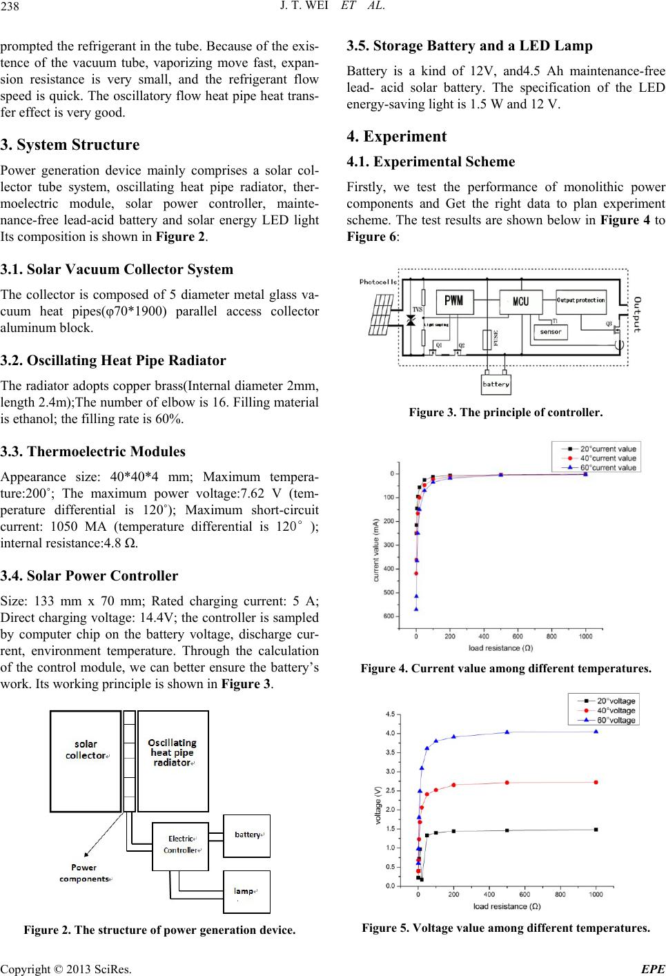
2. Principle
Solar thermoelectric generation is the use of the ther-
moelectric effect. The thermoelectric effect based on
thermoelectric materials at both ends of the carrier mo-
tion, so as to realize the conversion of energy forms [2].
As shown in Figure 1, The P type and N type two dif-
ferent types of thermoelectric material is connected with
the formation of PN junction. One side of this junction is
in the condition of high temperature, the other side is at a
low temperature state. PN type material high temperature
side concentration is higher than the low temperature
side. In the driving concentration gradient, electron dif-
fusion spread to the low temperature side. Thus the for-
mation of electromotive force has been made.
Capillary bend into oscillation flow heat pipe. It con-
sists of the evaporation heating section, adiabatic section
and condenser section. The heating section absorbs heat.
The heat is transferred to the condensation section
through the adiabatic section. Because of the tube vac-
uum, the refrigerant evaporation temperature is low, and
vaporization speed is fast. When heating, because the
heating period of absorption heat to make the tube steam
column becomes larger. At the same time, there are new
bubbles made. The bubble bigger push pipe steam col-
umn and liquid column flow. When the liquid and vapor
column after condensation segment, heat is released and
steam shrinks, because of the temperature of heating sec-
tion and condensing section. The bubble expands in the
heating section and shanks in the condensation side. Re-
ciprocating flow formed in the cold end pressure
Figure 1. Principle of thermoelectric power generation.
Copyright © 2013 SciRes. EPE
J. T. WEI ET AL.
238
prompted the refrigerant in the tube. Because of the exis-
tence of the vacuum tube, vaporizing move fast, expan-
sion resistance is very small, and the refrigerant flow
speed is quick. The oscillatory flow heat pipe heat trans-
fer effect is very good.
3. System Structure
Power generation device mainly comprises a solar col-
lector tube system, oscillating heat pipe radiator, ther-
moelectric module, solar power controller, mainte-
nance-free lead-acid battery and solar energy LED light
Its composition is shown in Figure 2.
3.1. Solar Vacuum Collector System
The collector is composed of 5 diameter metal glass va-
cuum heat pipes(φ70*1900) parallel access collector
aluminum block.
3.2. Oscillating Heat Pipe Radiator
The radiator adopts copper brass(Internal diameter 2mm,
length 2.4m);The number of elbow is 16. Filling material
is ethanol; the filling rate is 60%.
3.3. Thermoelectric Modules
Appearance size: 40*40*4 mm; Maximum tempera-
ture:200˚; The maximum power voltage:7.62 V (tem-
perature differential is 120˚); Maximum short-circuit
current: 1050 MA (temperature differential is 12);
internal resistance:4.8 .
3.4. Solar Power Controller
Size: 133 mm x 70 mm; Rated charging current: 5 A;
Direct charging voltage: 14.4V; the controller is sampled
by computer chip on the battery voltage, discharge cur-
rent, environment temperature. Through the calculation
of the control module, we can better ensure the battery’s
work. Its working principle is shown in Figure 3.
Figure 2. The structure of power generation device.
3.5. Storage Battery and a LED Lamp
Battery is a kind of 12V, and4.5 Ah maintenance-free
lead- acid solar battery. The specification of the LED
energy-saving light is 1.5 W and 12 V.
4. Experiment
4.1. Experimental Scheme
Firstly, we test the performance of monolithic power
components and Get the right data to plan experiment
scheme. The test results are shown below in Figure 4 to
Figure 6:
Figure 3. The principle of controller.
Figure 4. Current value among different temperatures.
Figure 5. Voltage value among different temperatures.
Copyright © 2013 SciRes. EPE
J. T. WEI ET AL. 239
Figure 6. Power value among different temperatures.
We can find out from the experiment that the best
matching resistor of single power components is 5-10 .
At this time at a fixed temperature difference, the power
of components is higher and the current is larger. Be-
cause of the small current in single power components
[3], it is not suitable for charging. The experimental plan
should adopt parallel and series combination. After many
times of calculation and test, we decide that 4 generation
components connected to a group. This is to ensure that
the output current reaches the charging current. Then
nine groups are in series. The purpose is to reach the
charging voltage.
Then we select one day of representative spring in
Changchun area to make the experiment. In the end, we
get the relationship between voltages, current, tempera-
ture and radiation. Testing time is from 7:50 to the end of
17:50. Results are shown from Figure 7 to figu r e 10:
Figure 7 shows that solar radiation peaks throughout
the whole day and noon time reaches the maximum value.
This is shown in Figure 8, the temperature of aluminum
block is the highest value in one day. The maximum
value can reach 8. Power generation equipment is in
the best condition at the same time.
Figure 8 shows that When the temperature of the heat
collecting aluminum block reached 79., the tempera-
ture of Radiator has a gradient change. The temperature
of bottom surface of Radiator has been greatly re-
duced .Then it has a oscillating variation. The radiator
should be in the oscillating heat pipe effect status. The
heat pipe cooling effect enhanced and Thermal resistance
is reduced. Then the heat collecting aluminum block
temperature ascension is also slow.
Figure 9 shows that the effect of oscillating heat pipe
makes open circuit voltage larger and reach to 12.8 V.
Battery can be charged in this time. In Figure 8 we can
know, in the experiment, the charging time is about one
hour and a half.
Figure 10 shows that open circuit current value has
been maintained at a relatively high value in the whole
experiment. It is owing to the parallel to the power as-
sembly. Because of Ohm law, Generating parallel can get
a large amount of current.
Figure 7. Radiation levels.
Figure 8. The temperature of aluminum block and the ra-
diator surface.
Figure 9. Relation between the voltage and time.
Copyright © 2013 SciRes. EPE
J. T. WEI ET AL.
Copyright © 2013 SciRes. EPE
240
Figure 10. Relation between the current and the time.
After several days of testing, In the similar weather
conditions, Charging battery for two to three days can
make LED lamp lighting and a long time lighting.
5. Feasibility Analysis
In most areas in China, there are lots of solar energy re-
sources. The average energy flow density of the solar
energy(I) is more than 1000W/m2.In some western prov-
inces, the highest value will reach 1750W/m2, the pho-
tothermal conversion efficiency value (η) of High-quality
solar collector is more than 0.75. The total area of single
tube sheet metal (s) is 0.25m2. This device has five tubes,
so total area of it(S) is S=5×0.25=1.25 m2. The average
daily sunshine time(T) is 4h. The average of daily col-
lected energy (E0) will be E0=I*T*S*η. If the percent-
age of the power (ξ) absorbed in the collector is 60%.
The efficiency of power components can reach 10% and
solar panel conversion rate was 95%.The total amount of
power:
E= E0*ξ*0.1*0.957.7×105J0.21kWh
Assumed that the family lighting power P=150W, the
device can generate electricity for 1.4 hours. If we im-
proved lighting equipment, lingting time will be greatly
extended.
6. Summary
The power system with no pollution, no noise, low
maintenance cost of oscillating heat pipe radiator has
high heat transfer efficiency. Therefore this device is in
accordance with the national development of low carbon
economy. This equipment is easy to transform and has
ability to adapt to the environment. So it is worth to po-
pularize. But the problems need to be solved are improv-
ing the radiation efficiency of the radiator and the power
efficiency of power assembly.
REFERENCES
[1] J. J. Zhou and W. L. Zhang, “Current status and charac-
teristics of thermoelectric material,” Journal of Hebei
Polytechnic University, 31, 2, 2009, pp.77-78.
[2] A. R. Ram and R. J. Solar, “thermoelectric generator for
micropower applications,” Electronic Materials, Vol. 39,
No. 9, 2010, pp.1735-1740.
doi:10.1007/s11664-010-1190-8
[3] Y. D. Deng, “Research on automobile exhaust thermoe-
lectric device and thermoelectric module layout,” Journal
of Wuhan University of Technology, Vol. 32, No. 2, 2010,
pp. 265-267.